Creation and first launch of a traveling wave thermo-acoustic engine
Here in this article - “Thermoacoustic engine - Stirling engine without pistons” , I wrote about how the Stirling engine was improved and reached the state of a thermoacoustic engine. In this article I will talk about how to build and test your own thermo-acoustic engine.
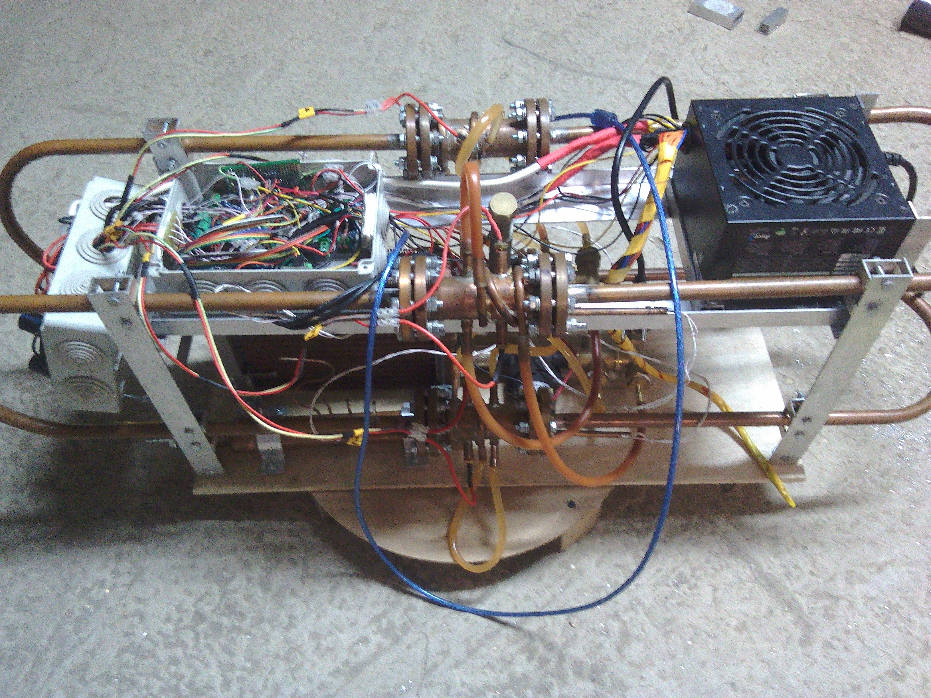
Fig.1. The four-stage thermo-acoustic engine with a traveling wave
Thermo-acoustic traveling-wave engine is an engine with external heat input. The engine converts thermal energy into acoustic energy, due to the completion of the thermodynamic cycle that is closest to the Stirling cycle. Further, acoustic energy can be converted into electricity using a bidirectional turbine connected to an electric generator and thus obtain a thermal generator with a minimum of moving parts and an electrical efficiency of 30–50% of the Carnot cycle efficiency.
Gifka. 1. Stirling alpha type
engine To begin, consider the alpha Stirling type engine. If we discard all the minor details, it consists of: a cylinder in which the compression, expansion and movement of gas occur; pistons, which actually carry out gas manipulations; heat exchangers that supply and dissipate thermal energy; and a regenerator that stores heat when the gas passes from the hot to the cold heat exchanger, and then gives off the heat when the gas moves back.
With a phase difference of 90 degrees between the movement of the pistons, a thermodynamic cycle is implemented, which ultimately performs work on the pistons. So usually describe the operation of the Stirling engine.
But you can look at this process differently. Looking at the gif of 1. for several days, it can be understood that gas compression, expansion and movement are essentially the same thing that happens in an acoustic wave. And if this is the same, then this is the acoustic wave.
Gifka. 2 One-stage thermo-acoustic engine with a traveling wave.
Thus, it is quite possible to get rid of the pistons and replace them with an acoustic resonator, in which an acoustic wave will form and perform all the work of the pistons.
This design is an acoustic self-oscillatory system, which can be compared with an electrical self-oscillatory system. There is a resonator (as a resonant circuit in the electrical circuit) in the form of a looped tube and an element that amplifies acoustic oscillations — a regenerator (as a power source, connected at the right time in the electrical circuit). As the temperature difference between the heat exchangers increases, the power gain of the acoustic wave passing through the regenerator increases. When the gain in the regenerator becomes greater than the attenuation when a wave passes through the remaining elements, the engine starts up automatically.
At the very initial moment of time, when the engine starts, there is an increase in noise oscillations that are inevitably present in the gas. Moreover, out of the entire spectrum of noise, only oscillations with a wavelength equal to the length of the motor housing (Wavelength with the main resonant frequency) are amplified. And further, when the engine is running, the vast majority of acoustic energy falls on a wave with a fundamental resonant frequency. This acoustic wave is the sum of traveling and standing waves. The standing component of the wave arises due to the reflection of part of the wave from the heat exchangers and the regenerator and the imposition of this reflected wave on the main one. The presence of the standing component of the wave reduces the efficiency that must be considered when designing the engine.
Consider a free running wave. Such a wave occurs in the resonator of the engine.
Gifka. 3 Plots of temperature and pressure in a traveling acoustic wave in a resonator
In the resonator, the wave interacts very weakly with the walls of the resonator (gif. 3), since the diameter of the resonator is too large to have a strong influence on such gas parameters as temperature and pressure. But the influence is still there. First, the resonator sets the direction of wave movement, secondly, the wave loses energy in the resonator due to the interaction with the wall in the boundary gas layer. In the animation, you can see that an arbitrarily taken elementary portion of the gas in the free wave heats up during compression and cools down during expansion, that is, it contracts and expands almost adiabatically. Almost adiabatically, this is because gas has thermal conductivity, albeit small. In this case, in a free wave, the dependence of pressure on volume (PV diagram) is a line. That is, as gas does not do work,
A completely different picture is observed in the engine regenerator.
Gifka. 4 Charts of temperature and pressure in the regenerator
In the presence of the regenerator, the gas expands and contracts no longer adiabatically. During compression, the gas gives off thermal energy to the regenerator, and during expansion it takes energy and the dependence of pressure on volume is already an oval. The area of this oval is numerically equal to the work done on gas. Thus, in each cycle, work is done, which leads to increased acoustic oscillations. On GIF 4 on the temperature graph, the white line is the temperature of the surface of the regenerator, and the blue is the temperature of the elementary portion of the gas.
The main postulates in the interaction of the wave with the regenerator are as follows: the first postulate - there is a temperature gradient in the regenerator with a maximum at the hot heat exchanger and a minimum at the cold one and the second postulate is that the gas strongly interacts thermally with the surface of the regenerator, that is, it immediately takes on the local temperature of the regenerator (blue line lies on white). In order to achieve a good thermal contact between the gas and the regenerator, it is necessary to make pores in the regenerator of small sizes - about 0.1 mm and less (depending on the gas used and the pressure in the engine).
What is the regenerator? Usually it is a stack of steel grids. Here, in the animation, it is shown as a set of parallel plates. Such regenerators also exist, but more difficult to manufacture than from grids.
Fig.2. Designations of elements of a single-stage engine
About heat exchangers, a regenerator and a resonator everything is already clear. But usually a secondary cold heat exchanger is added to the engine. Its main goal is to prevent the cavity cavity from heating with a hot heat exchanger. The high temperature of the gas in the resonator is bad because the hot gas has a higher viscosity, which means higher losses in the wave, then the high temperature reduces the strength of the resonator, and there is often a need to put into the resonator far from heat-resistant equipment, such as a plastic turbogenerator heating. The cavity between the hot heat exchanger and the secondary cold is called the thermal buffer tube. It must be of such length that the thermal interaction between the heat exchangers is not significant.
The greatest efficiency is achieved when the turbine is installed in the resonator from the side of the hot heat exchanger, that is, immediately after the secondary cold one.
The one-stage engine shown in Fig. 2 is called the Taperli engine, since its design was first invented by Peter Taperli.
Fig.3. The scheme of the four-
stage engine One-stage design can be improved. In 2010, De Blok proposed a variant of a four-stage engine (Fig. 3). He increased the diameter of the heat exchangers and the regenerator relative to the diameter of the resonator in order to reduce the gas velocity in the regenerator area and thereby reduce the friction of the gas on the regenerator, and also increased the number of steps to four. An increase in the number of stages leads to a decrease in acoustic energy losses. Firstly, the length of the resonator for each stage is reduced and the energy loss in the resonator is reduced. Second, the difference between the velocity and pressure phases in the regenerator zone decreases (the standing wave component is removed). This reduces the minimum temperature difference required to start the engine.
So - you can build an engine with two, with three and more than four steps. The choice of the number of steps is a debatable question.
Other things being equal, the engine power is determined by the diameter of the step; the larger it is, the greater the power. The length of the motor housing should be chosen such that the oscillation frequency is preferably less than 100 Hz. If the body is too short - that is, when the oscillation frequency is too high, the loss of acoustic energy increases.
Next, I will describe the construction of such an engine.
The engine that I will describe is a mini test prototype. It is not planned that he will generate electricity. It is needed for working out the technology of converting thermal energy into acoustic energy, and it is too small to integrate a turbine into it and generate electricity. To generate electricity to prepare a larger prototype.
Fig. 4. Case
So, I started the production from the case. It consists of 4 stages and 4 resonators and is topologically a hollow bagel bent twice in half by 180 degrees. The steps are connected to the resonators with the help of flanges. The whole body is made of copper. This is necessary in order to be able to quickly solder anything into the case and just as quickly evaporate. The resonators are made of a copper tube with an outer diameter of 15 mm and an inner diameter of 13 mm. A step from a pipe with an external diameter of 35 mm and an internal 33 mm. Step length from flange to flange - 100 mm. The total length of the hull is 4 m.
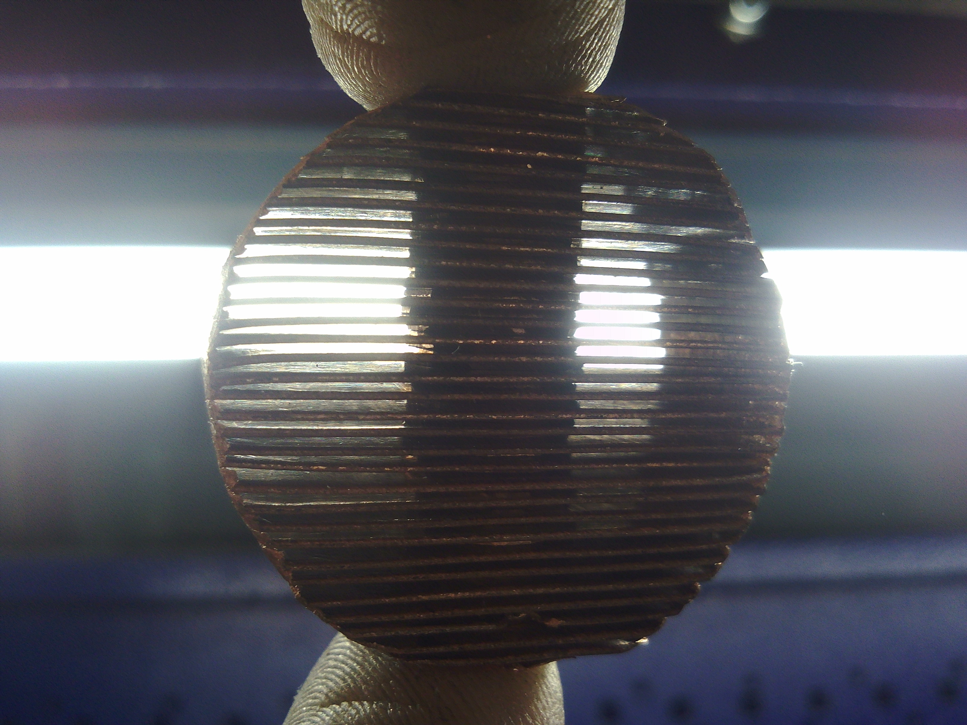
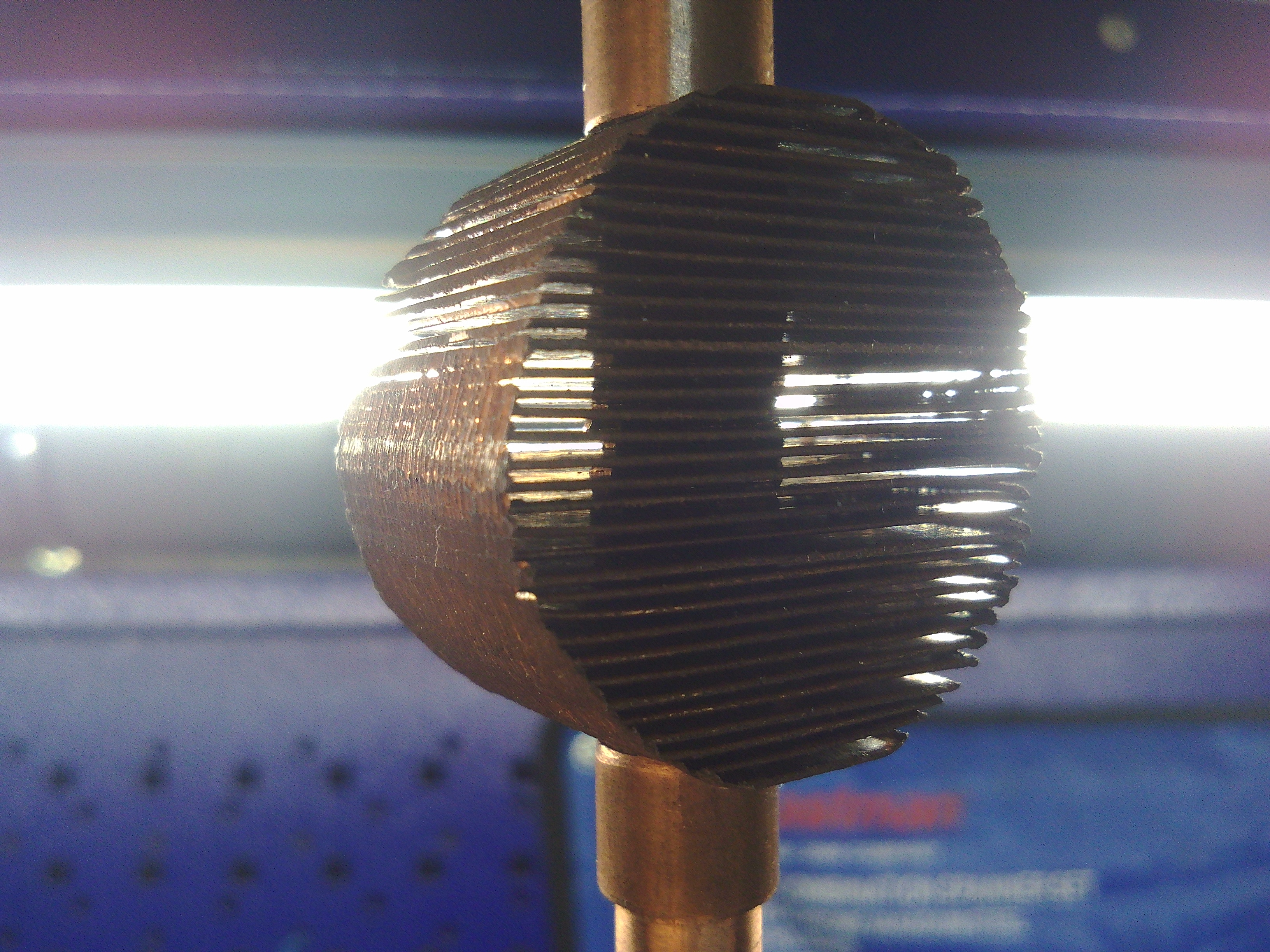
Figure. 5. Hot (left) and cold (right) heat exchangers
Then made heat exchangers. These are lamellar heat exchangers. The main structural elements of these heat exchangers are such copper plates and washers.
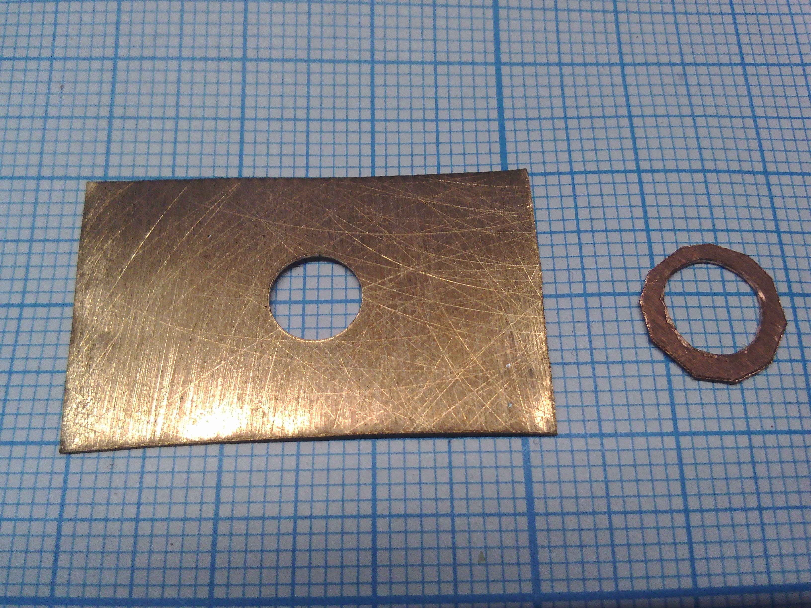
Fig. 6. Copper plate and copper washer.
Dimensions of heat exchangers: diameter about 32.5 mm, plate thickness 0.5 mm, distance between the plates 0.5 mm, external diameter of the washer 10 mm, internal 7 mm, length of the cold heat exchanger 20 mm, hot 15 mm
In a hot heat exchanger, electrical heating is carried out using a nichrome filament installed in the central hole. Maximum thermal power 100 watts. It would be paradoxical to use electricity to start an electric generator, but this is very convenient for a test prototype. The use of heating with electricity and not with gas or any other thermal energy eliminates the difficulty in calculating the incoming thermal energy, since in the case of electric heating it is sufficient to simply multiply the voltage by the current and the incoming thermal power will be accurately known. Accurately measure incoming heat output - this is important for calculating efficiency.
The cold heat exchanger is cooled by passing coolant, in this case water, through the central channel. The water heated in the heat exchanger enters the external cooling radiator, which is used as a radiator from the stove of such a supercar as “Zhiguli”
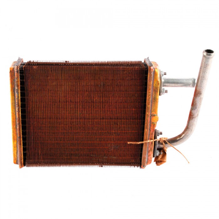
Fig. 7. Copper radiator heater from the VAZ-2101-8101050
After passing through the cooling radiator water returns to the cold heat exchanger. The water is circulated by a Topsflo Solar DC Circulation Pump 5 PV DC circulating pump.
Fig. 8. Circulation water pump 12V
Fig. 9. One of the regenerator grids
Regenerator - a stack of 20 pieces of stainless steel grids with a wire diameter of 0.2 mm and a distance between the wires in the grid is 0.71 mm
Fig. 10. Details of one stage
Fig. 11. Step in the section
In these figures it can be seen that in addition to the heat exchangers and the regenerator, there are aluminum inserts inside the step. They are simply needed so that the wires for the hot heat exchanger and the fittings for the cold heat exchanger can be brought out through the pipe wall. Without these inserts, it would be necessary to withdraw them through the flanges, which is very unpleasant or even impossible. So in each of the inserts there is a hole with a diameter of 13 mm, exactly the same as the diameter of the resonator and thus the insert does not differ in its acoustic properties from the resonator - that is, is its continuation.
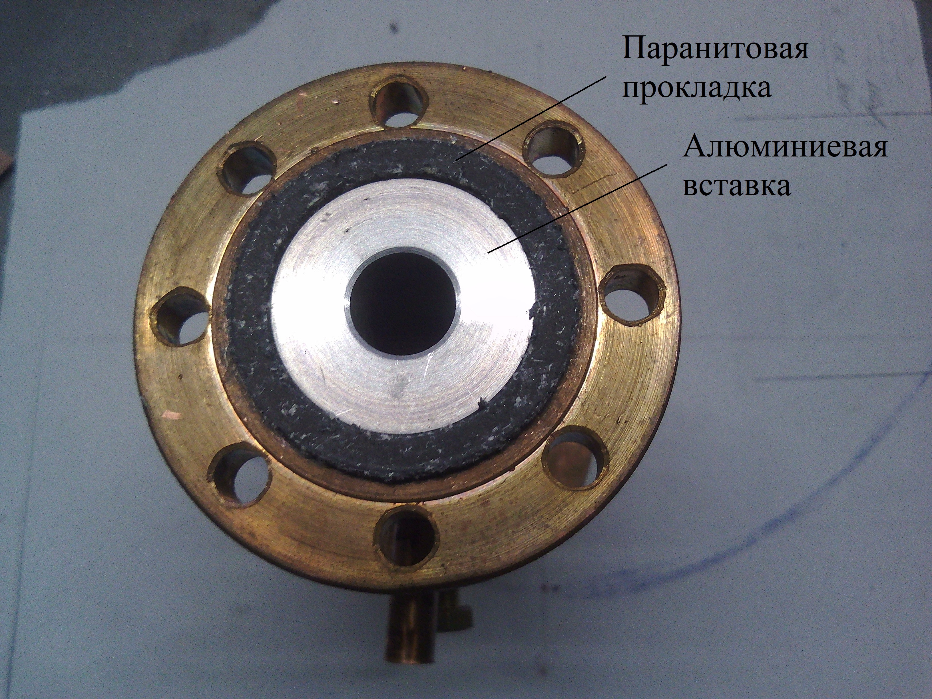
Fig. 12. Aluminum insert in the case
This is how the cold heat exchanger inside the case looks like:
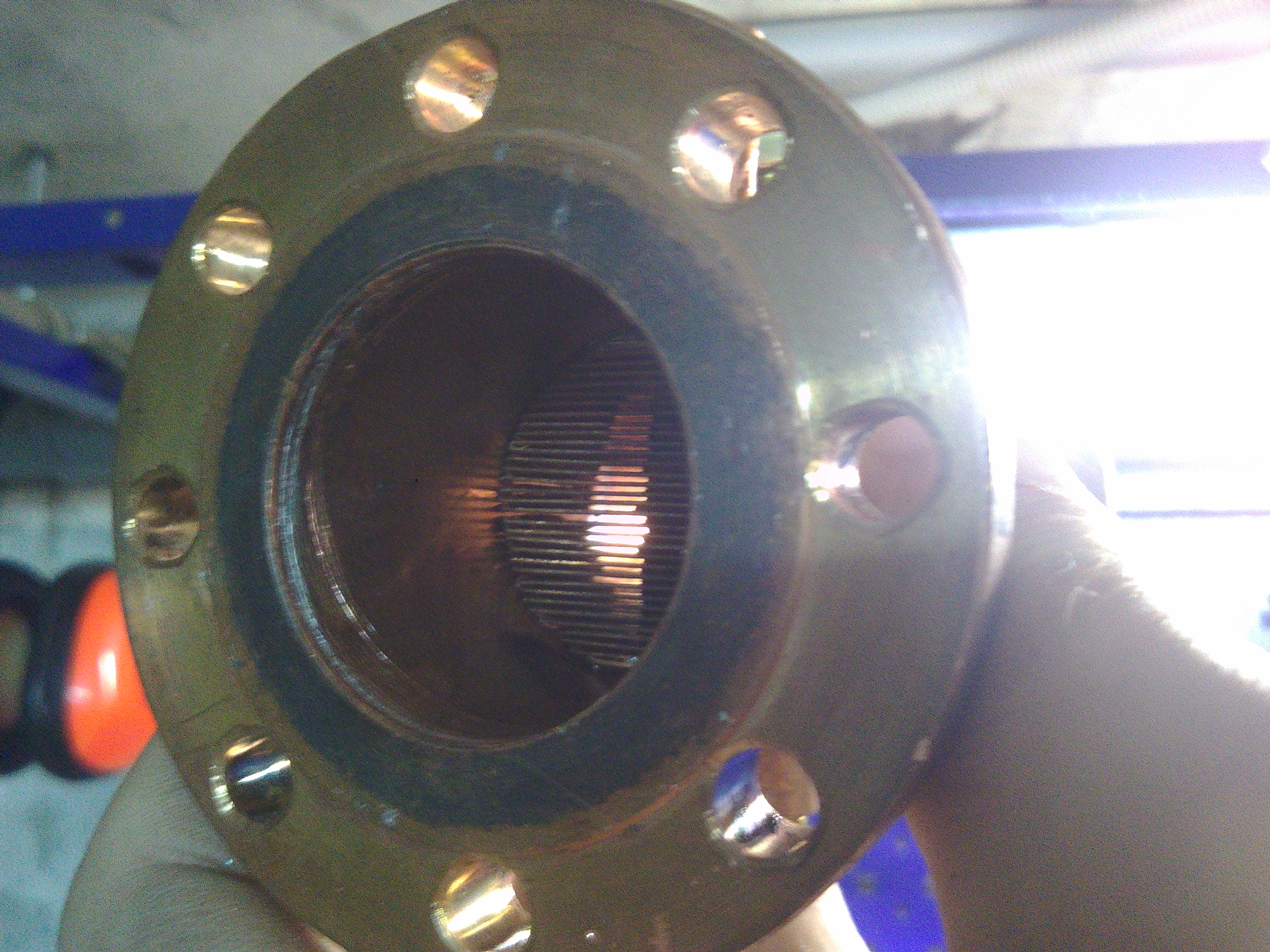
Fig. 13. Sealed heat exchanger
I chose 12 V as the main voltage of the entire system, since it is easy to find a cheap and powerful enough power supply unit - a power supply for a computer. I chose the Aerocool VX 650W power supply, since the maximum required electrical power should be slightly more than 400 watts.
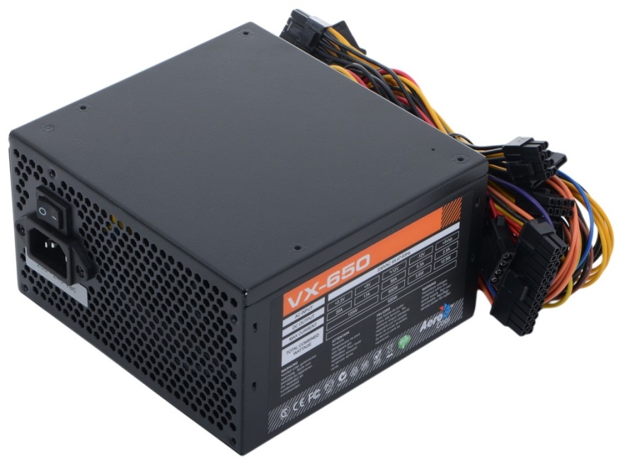
Fig. 14. Power supply Aerocool VX 650W I
used Arduino Mega 2560 as a system controller. I connected all sensors and controllers to it
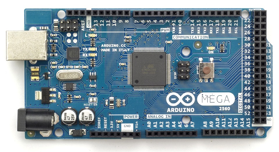
Fig. 15. Arduino Mega 2560
A The heating power of hot heat exchangers is regulated by Pulse Width Modulation. For this, I used a four-channel transistor driver IRF 520 for Arduino.
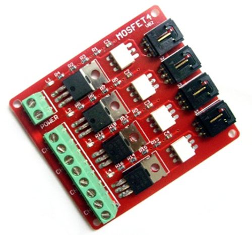
Fig. 16. Four-channel transistor driver IRF 520 for Arduino
Transistors had to be placed on the radiator, because they were out of order from overheating already at a power above 10 W through a transistor.
The pump power control was also carried out using PWM, but only through the module - the Troyka-Mosfet V3 power switch.
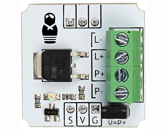
Fig. 17. Troyka-Mosfet V3 - power switch based on IRLR8113 for Arduino. The
measurement of the current passing through the hot heat exchangers is carried out using a 20 A current sensor for Arduino.
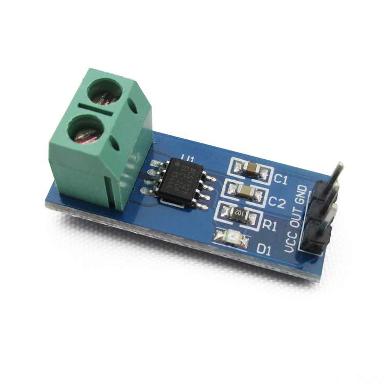
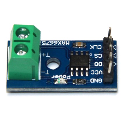
Fig. 18. Current sensor 20 A (left) and a module for thermocouples of type K - MAX6675 (right)
It is also necessary to measure the temperature of heat exchangers, for this purpose, thermocouples of type K and a module for thermocouples of type K - MAX6675, which digitizes voltage from thermocouples, are used. it is too small to feed it directly to the Arduino.
Fig. 19. Type K thermocouples in a copper tube
Thermocouples are glued into copper tubes using a high-temperature sealant on the weld side and using epoxy resin on the wire side. This is done in order to solder them into the copper motor housing
Now it remains only to measure the pressure in the engine and acoustic oscillations, that is, pressure fluctuations, to find out the acoustic power of the engine. On the one hand, it is possible to measure the average engine pressure per cycle (reference pressure) and sinusoidal pressure fluctuations with the same absolute pressure sensor. But in this case, most of the sensor measurement range will not be used, since the amplitude of pressure fluctuations is 10 or more times smaller than the reference pressure itself. That is, the measurement of pressure fluctuations remains a small resolution. Therefore, it was necessary to separate the reference pressure and pressure oscillations in order to measure pressure oscillations by another sensor - a sensor with a measurement range suitable for the amplitude of oscillations in the wave. For these purposes, a small buffer tank was made and connected to the cavity of the engine through a very thin capillary tube. The tube is so thin that filling the tank through it with a pressure of 1 atm takes about 3 seconds.
Fig. 20. Buffer tank for measuring pressure oscillations in the resonator.
Why is this all done? And for the fact that due to the capillary tube, the average pressure per cycle is formed in the buffer tank, because the typical oscillation frequency in the engine is 80 Hz, that is, the period is 0.0125 seconds, and the pressure increase by the magnitude of the oscillation amplitude takes about a second. Thus, pressure fluctuations in the tank are excluded, but at the same time there is an average pressure per cycle, and the relative pressure between this tank and the engine can already be measured. This is exactly what we needed.
The pressure in the engine can be increased to 5 atm with the help of an automobile foot pump.
To measure the average pressure per cycle, an MPX5700AP absolute pressure sensor was connected to the buffer tank, and a differential pressure sensor MPX5050DP between the tank and the motor resonator was connected to measure pressure fluctuations.
Fig. 21. MPX5700AP absolute pressure sensor (left) and MPX5050DP differential pressure sensor (right)
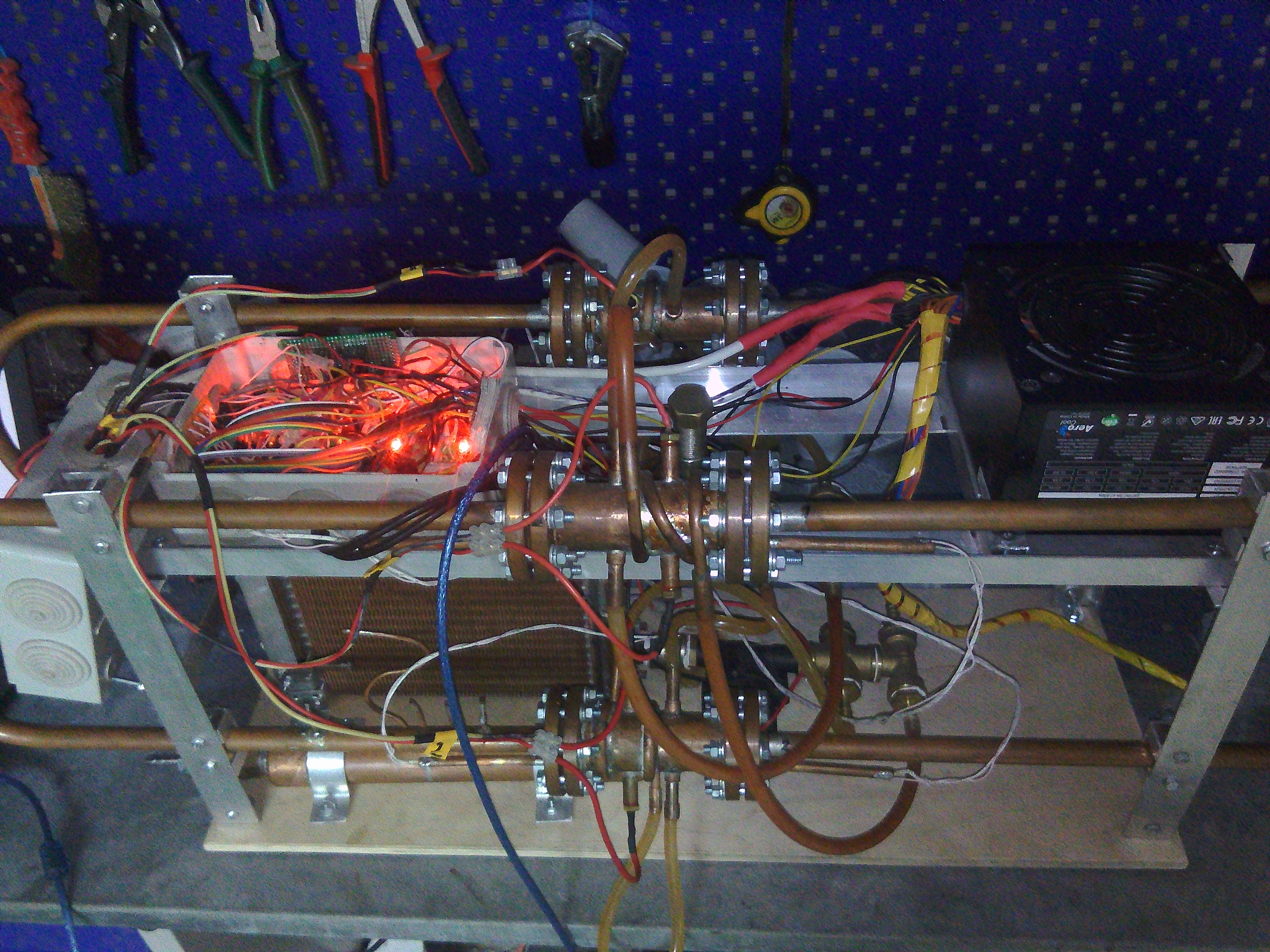
Fig. 22. Beautiful glow of the sensors when the engine is running in the dark.
The first attempt to start the engine took place from the finished one of four stages. The remaining steps were empty (without heat exchangers and regenerator). When the hot heat exchanger is heated up to a maximum temperature of 250 degrees Celsius, no start has taken place.
Then a second launch attempt took place on two steps. Steps were located at a distance of half the length of the body from each other. Again, when the hot heat exchangers are heated to 250 degrees, the engine did not start. The temperature of cold heat exchangers in all experiments was about 40 degrees Celsius, the working body in all experiments was air having atmospheric pressure.
The first successful launch took place at work all 4 steps. The temperature of hot heat exchangers at the time of launch was 125 degrees. When operating at a maximum thermal power of 372 W (that is, 93 W per one heat exchanger), the temperature of the hot heat exchangers was 175 degrees, and the cold 44. The measured oscillation frequency is 74 Hz. The power of the acoustic wave in the resonator is 27.6 watts. The efficiency of converting thermal energy into acoustic energy has not yet been measured, since this requires additional pressure sensors, which must be located before and after the stage, to measure the increase in acoustic power at the stage. In addition, for experiments to determine the efficiency you need to put the load inside the engine, but this is the topic of the next story ...
At 3 out of 4 steps, the engine also works. The temperature of the three hot heat exchangers at startup is about 175 degrees. The fourth - an untapped stage at the same time works in the mode of a heat pump or a refrigerator (it depends on the point of view, on what we need, heating or cooling). That is, the cold heat exchanger of the unused stage has a temperature like that of all other cold heat exchangers, and the hot heat exchanger begins to cool, as the acoustic wave removes thermal energy from it. In the experiment, the maximum cooling obtained in this way was 10 degrees.
What surprised me at the start was the fact that absolute tightness was not critical for the operation of the device. That is, during the first launches, the tubes, to which the buffer tank and the pressure sensor were to be connected, were not plugged in anything. The diameter of each of the two holes was about 2.5 mm. That is, the engine was absolutely not sealed, and it still did not prevent him from starting and working successfully. You could even bring a finger to the tubes and feel the vibrations of the air. When the tubes were plugged, the temperature of hot heat exchangers began to drop significantly (by 20–30 degrees) and the temperature of cold ones increased by 5–10 degrees. This is direct evidence that during sealing, acoustic energy inside the case increases and thus the heat exchange between the heat exchangers increases, due to the thermo-acoustic effect.
Then, many were worried that the engine would be very loud during operation. And indeed, you might think so, because the measured sound volume in the resonator was 171.5 Decibels. But the thing is that the whole wave is enclosed inside the engine and in fact it turned out to be so silent that its work can be determined externally only by a small vibration of the body.
I create by means of thermoacoustics in Engels, in the engineering club Sol-En. Those who are also inspired by this direction of creativity and who would like to join in the future, write to personal messages from which city you are from.
Fig.1. The four-stage thermo-acoustic engine with a traveling wave
Thermo-acoustic traveling-wave engine is an engine with external heat input. The engine converts thermal energy into acoustic energy, due to the completion of the thermodynamic cycle that is closest to the Stirling cycle. Further, acoustic energy can be converted into electricity using a bidirectional turbine connected to an electric generator and thus obtain a thermal generator with a minimum of moving parts and an electrical efficiency of 30–50% of the Carnot cycle efficiency.
What is the principle of the engine?
Gifka. 1. Stirling alpha type
engine To begin, consider the alpha Stirling type engine. If we discard all the minor details, it consists of: a cylinder in which the compression, expansion and movement of gas occur; pistons, which actually carry out gas manipulations; heat exchangers that supply and dissipate thermal energy; and a regenerator that stores heat when the gas passes from the hot to the cold heat exchanger, and then gives off the heat when the gas moves back.
With a phase difference of 90 degrees between the movement of the pistons, a thermodynamic cycle is implemented, which ultimately performs work on the pistons. So usually describe the operation of the Stirling engine.
But you can look at this process differently. Looking at the gif of 1. for several days, it can be understood that gas compression, expansion and movement are essentially the same thing that happens in an acoustic wave. And if this is the same, then this is the acoustic wave.
Gifka. 2 One-stage thermo-acoustic engine with a traveling wave.
Thus, it is quite possible to get rid of the pistons and replace them with an acoustic resonator, in which an acoustic wave will form and perform all the work of the pistons.
This design is an acoustic self-oscillatory system, which can be compared with an electrical self-oscillatory system. There is a resonator (as a resonant circuit in the electrical circuit) in the form of a looped tube and an element that amplifies acoustic oscillations — a regenerator (as a power source, connected at the right time in the electrical circuit). As the temperature difference between the heat exchangers increases, the power gain of the acoustic wave passing through the regenerator increases. When the gain in the regenerator becomes greater than the attenuation when a wave passes through the remaining elements, the engine starts up automatically.
At the very initial moment of time, when the engine starts, there is an increase in noise oscillations that are inevitably present in the gas. Moreover, out of the entire spectrum of noise, only oscillations with a wavelength equal to the length of the motor housing (Wavelength with the main resonant frequency) are amplified. And further, when the engine is running, the vast majority of acoustic energy falls on a wave with a fundamental resonant frequency. This acoustic wave is the sum of traveling and standing waves. The standing component of the wave arises due to the reflection of part of the wave from the heat exchangers and the regenerator and the imposition of this reflected wave on the main one. The presence of the standing component of the wave reduces the efficiency that must be considered when designing the engine.
Consider a free running wave. Such a wave occurs in the resonator of the engine.
Gifka. 3 Plots of temperature and pressure in a traveling acoustic wave in a resonator
In the resonator, the wave interacts very weakly with the walls of the resonator (gif. 3), since the diameter of the resonator is too large to have a strong influence on such gas parameters as temperature and pressure. But the influence is still there. First, the resonator sets the direction of wave movement, secondly, the wave loses energy in the resonator due to the interaction with the wall in the boundary gas layer. In the animation, you can see that an arbitrarily taken elementary portion of the gas in the free wave heats up during compression and cools down during expansion, that is, it contracts and expands almost adiabatically. Almost adiabatically, this is because gas has thermal conductivity, albeit small. In this case, in a free wave, the dependence of pressure on volume (PV diagram) is a line. That is, as gas does not do work,
A completely different picture is observed in the engine regenerator.
Gifka. 4 Charts of temperature and pressure in the regenerator
In the presence of the regenerator, the gas expands and contracts no longer adiabatically. During compression, the gas gives off thermal energy to the regenerator, and during expansion it takes energy and the dependence of pressure on volume is already an oval. The area of this oval is numerically equal to the work done on gas. Thus, in each cycle, work is done, which leads to increased acoustic oscillations. On GIF 4 on the temperature graph, the white line is the temperature of the surface of the regenerator, and the blue is the temperature of the elementary portion of the gas.
The main postulates in the interaction of the wave with the regenerator are as follows: the first postulate - there is a temperature gradient in the regenerator with a maximum at the hot heat exchanger and a minimum at the cold one and the second postulate is that the gas strongly interacts thermally with the surface of the regenerator, that is, it immediately takes on the local temperature of the regenerator (blue line lies on white). In order to achieve a good thermal contact between the gas and the regenerator, it is necessary to make pores in the regenerator of small sizes - about 0.1 mm and less (depending on the gas used and the pressure in the engine).
What is the regenerator? Usually it is a stack of steel grids. Here, in the animation, it is shown as a set of parallel plates. Such regenerators also exist, but more difficult to manufacture than from grids.
What does a traveling-wave thermo-acoustic engine consist of?
Fig.2. Designations of elements of a single-stage engine
About heat exchangers, a regenerator and a resonator everything is already clear. But usually a secondary cold heat exchanger is added to the engine. Its main goal is to prevent the cavity cavity from heating with a hot heat exchanger. The high temperature of the gas in the resonator is bad because the hot gas has a higher viscosity, which means higher losses in the wave, then the high temperature reduces the strength of the resonator, and there is often a need to put into the resonator far from heat-resistant equipment, such as a plastic turbogenerator heating. The cavity between the hot heat exchanger and the secondary cold is called the thermal buffer tube. It must be of such length that the thermal interaction between the heat exchangers is not significant.
The greatest efficiency is achieved when the turbine is installed in the resonator from the side of the hot heat exchanger, that is, immediately after the secondary cold one.
The one-stage engine shown in Fig. 2 is called the Taperli engine, since its design was first invented by Peter Taperli.
Fig.3. The scheme of the four-
stage engine One-stage design can be improved. In 2010, De Blok proposed a variant of a four-stage engine (Fig. 3). He increased the diameter of the heat exchangers and the regenerator relative to the diameter of the resonator in order to reduce the gas velocity in the regenerator area and thereby reduce the friction of the gas on the regenerator, and also increased the number of steps to four. An increase in the number of stages leads to a decrease in acoustic energy losses. Firstly, the length of the resonator for each stage is reduced and the energy loss in the resonator is reduced. Second, the difference between the velocity and pressure phases in the regenerator zone decreases (the standing wave component is removed). This reduces the minimum temperature difference required to start the engine.
So - you can build an engine with two, with three and more than four steps. The choice of the number of steps is a debatable question.
Other things being equal, the engine power is determined by the diameter of the step; the larger it is, the greater the power. The length of the motor housing should be chosen such that the oscillation frequency is preferably less than 100 Hz. If the body is too short - that is, when the oscillation frequency is too high, the loss of acoustic energy increases.
Next, I will describe the construction of such an engine.
Making engine
The engine that I will describe is a mini test prototype. It is not planned that he will generate electricity. It is needed for working out the technology of converting thermal energy into acoustic energy, and it is too small to integrate a turbine into it and generate electricity. To generate electricity to prepare a larger prototype.
Fig. 4. Case
So, I started the production from the case. It consists of 4 stages and 4 resonators and is topologically a hollow bagel bent twice in half by 180 degrees. The steps are connected to the resonators with the help of flanges. The whole body is made of copper. This is necessary in order to be able to quickly solder anything into the case and just as quickly evaporate. The resonators are made of a copper tube with an outer diameter of 15 mm and an inner diameter of 13 mm. A step from a pipe with an external diameter of 35 mm and an internal 33 mm. Step length from flange to flange - 100 mm. The total length of the hull is 4 m.
Figure. 5. Hot (left) and cold (right) heat exchangers
Then made heat exchangers. These are lamellar heat exchangers. The main structural elements of these heat exchangers are such copper plates and washers.
Fig. 6. Copper plate and copper washer.
Dimensions of heat exchangers: diameter about 32.5 mm, plate thickness 0.5 mm, distance between the plates 0.5 mm, external diameter of the washer 10 mm, internal 7 mm, length of the cold heat exchanger 20 mm, hot 15 mm
In a hot heat exchanger, electrical heating is carried out using a nichrome filament installed in the central hole. Maximum thermal power 100 watts. It would be paradoxical to use electricity to start an electric generator, but this is very convenient for a test prototype. The use of heating with electricity and not with gas or any other thermal energy eliminates the difficulty in calculating the incoming thermal energy, since in the case of electric heating it is sufficient to simply multiply the voltage by the current and the incoming thermal power will be accurately known. Accurately measure incoming heat output - this is important for calculating efficiency.
The cold heat exchanger is cooled by passing coolant, in this case water, through the central channel. The water heated in the heat exchanger enters the external cooling radiator, which is used as a radiator from the stove of such a supercar as “Zhiguli”
Fig. 7. Copper radiator heater from the VAZ-2101-8101050
After passing through the cooling radiator water returns to the cold heat exchanger. The water is circulated by a Topsflo Solar DC Circulation Pump 5 PV DC circulating pump.
Fig. 8. Circulation water pump 12V
Fig. 9. One of the regenerator grids
Regenerator - a stack of 20 pieces of stainless steel grids with a wire diameter of 0.2 mm and a distance between the wires in the grid is 0.71 mm
Fig. 10. Details of one stage
Fig. 11. Step in the section
In these figures it can be seen that in addition to the heat exchangers and the regenerator, there are aluminum inserts inside the step. They are simply needed so that the wires for the hot heat exchanger and the fittings for the cold heat exchanger can be brought out through the pipe wall. Without these inserts, it would be necessary to withdraw them through the flanges, which is very unpleasant or even impossible. So in each of the inserts there is a hole with a diameter of 13 mm, exactly the same as the diameter of the resonator and thus the insert does not differ in its acoustic properties from the resonator - that is, is its continuation.
Fig. 12. Aluminum insert in the case
This is how the cold heat exchanger inside the case looks like:
Fig. 13. Sealed heat exchanger
Electronics and measuring equipment
I chose 12 V as the main voltage of the entire system, since it is easy to find a cheap and powerful enough power supply unit - a power supply for a computer. I chose the Aerocool VX 650W power supply, since the maximum required electrical power should be slightly more than 400 watts.
Fig. 14. Power supply Aerocool VX 650W I
used Arduino Mega 2560 as a system controller. I connected all sensors and controllers to it
Fig. 15. Arduino Mega 2560
A The heating power of hot heat exchangers is regulated by Pulse Width Modulation. For this, I used a four-channel transistor driver IRF 520 for Arduino.
Fig. 16. Four-channel transistor driver IRF 520 for Arduino
Transistors had to be placed on the radiator, because they were out of order from overheating already at a power above 10 W through a transistor.
The pump power control was also carried out using PWM, but only through the module - the Troyka-Mosfet V3 power switch.
Fig. 17. Troyka-Mosfet V3 - power switch based on IRLR8113 for Arduino. The
measurement of the current passing through the hot heat exchangers is carried out using a 20 A current sensor for Arduino.
Fig. 18. Current sensor 20 A (left) and a module for thermocouples of type K - MAX6675 (right)
It is also necessary to measure the temperature of heat exchangers, for this purpose, thermocouples of type K and a module for thermocouples of type K - MAX6675, which digitizes voltage from thermocouples, are used. it is too small to feed it directly to the Arduino.
Fig. 19. Type K thermocouples in a copper tube
Thermocouples are glued into copper tubes using a high-temperature sealant on the weld side and using epoxy resin on the wire side. This is done in order to solder them into the copper motor housing
Now it remains only to measure the pressure in the engine and acoustic oscillations, that is, pressure fluctuations, to find out the acoustic power of the engine. On the one hand, it is possible to measure the average engine pressure per cycle (reference pressure) and sinusoidal pressure fluctuations with the same absolute pressure sensor. But in this case, most of the sensor measurement range will not be used, since the amplitude of pressure fluctuations is 10 or more times smaller than the reference pressure itself. That is, the measurement of pressure fluctuations remains a small resolution. Therefore, it was necessary to separate the reference pressure and pressure oscillations in order to measure pressure oscillations by another sensor - a sensor with a measurement range suitable for the amplitude of oscillations in the wave. For these purposes, a small buffer tank was made and connected to the cavity of the engine through a very thin capillary tube. The tube is so thin that filling the tank through it with a pressure of 1 atm takes about 3 seconds.
Fig. 20. Buffer tank for measuring pressure oscillations in the resonator.
Why is this all done? And for the fact that due to the capillary tube, the average pressure per cycle is formed in the buffer tank, because the typical oscillation frequency in the engine is 80 Hz, that is, the period is 0.0125 seconds, and the pressure increase by the magnitude of the oscillation amplitude takes about a second. Thus, pressure fluctuations in the tank are excluded, but at the same time there is an average pressure per cycle, and the relative pressure between this tank and the engine can already be measured. This is exactly what we needed.
The pressure in the engine can be increased to 5 atm with the help of an automobile foot pump.
To measure the average pressure per cycle, an MPX5700AP absolute pressure sensor was connected to the buffer tank, and a differential pressure sensor MPX5050DP between the tank and the motor resonator was connected to measure pressure fluctuations.
Fig. 21. MPX5700AP absolute pressure sensor (left) and MPX5050DP differential pressure sensor (right)
First start
Fig. 22. Beautiful glow of the sensors when the engine is running in the dark.
The first attempt to start the engine took place from the finished one of four stages. The remaining steps were empty (without heat exchangers and regenerator). When the hot heat exchanger is heated up to a maximum temperature of 250 degrees Celsius, no start has taken place.
Then a second launch attempt took place on two steps. Steps were located at a distance of half the length of the body from each other. Again, when the hot heat exchangers are heated to 250 degrees, the engine did not start. The temperature of cold heat exchangers in all experiments was about 40 degrees Celsius, the working body in all experiments was air having atmospheric pressure.
The first successful launch took place at work all 4 steps. The temperature of hot heat exchangers at the time of launch was 125 degrees. When operating at a maximum thermal power of 372 W (that is, 93 W per one heat exchanger), the temperature of the hot heat exchangers was 175 degrees, and the cold 44. The measured oscillation frequency is 74 Hz. The power of the acoustic wave in the resonator is 27.6 watts. The efficiency of converting thermal energy into acoustic energy has not yet been measured, since this requires additional pressure sensors, which must be located before and after the stage, to measure the increase in acoustic power at the stage. In addition, for experiments to determine the efficiency you need to put the load inside the engine, but this is the topic of the next story ...
At 3 out of 4 steps, the engine also works. The temperature of the three hot heat exchangers at startup is about 175 degrees. The fourth - an untapped stage at the same time works in the mode of a heat pump or a refrigerator (it depends on the point of view, on what we need, heating or cooling). That is, the cold heat exchanger of the unused stage has a temperature like that of all other cold heat exchangers, and the hot heat exchanger begins to cool, as the acoustic wave removes thermal energy from it. In the experiment, the maximum cooling obtained in this way was 10 degrees.
What surprised me at the start was the fact that absolute tightness was not critical for the operation of the device. That is, during the first launches, the tubes, to which the buffer tank and the pressure sensor were to be connected, were not plugged in anything. The diameter of each of the two holes was about 2.5 mm. That is, the engine was absolutely not sealed, and it still did not prevent him from starting and working successfully. You could even bring a finger to the tubes and feel the vibrations of the air. When the tubes were plugged, the temperature of hot heat exchangers began to drop significantly (by 20–30 degrees) and the temperature of cold ones increased by 5–10 degrees. This is direct evidence that during sealing, acoustic energy inside the case increases and thus the heat exchange between the heat exchangers increases, due to the thermo-acoustic effect.
Then, many were worried that the engine would be very loud during operation. And indeed, you might think so, because the measured sound volume in the resonator was 171.5 Decibels. But the thing is that the whole wave is enclosed inside the engine and in fact it turned out to be so silent that its work can be determined externally only by a small vibration of the body.
Invitation to join the project
I create by means of thermoacoustics in Engels, in the engineering club Sol-En. Those who are also inspired by this direction of creativity and who would like to join in the future, write to personal messages from which city you are from.