Arduino-compatible PLC CONTROLLINO, part 1
For the first time about a programmable logic controller called CONTROLLINO, I happened to find out a year back in 2014 in a casual correspondence with a person who selected a PLC for home automation. I recommended some classic models to him, and he said in response, they say, he saw on Kickstarter some interesting project called CONTROLLINIO. This is an industrial PLC, which is programmed in the same way as Arduino, in its native IDE.
That guy worked as a php programmer and C ++ was not a problem for him. He had money and ideas, but there was no desire to study LAD or Codesys. As a result, he unsubscribed that he made a pre-order for CONTROLLINO and did not contact me anymore.
I do not know what and how it happened in the end, but after 3 years I had a chance to work with this device.
While I was creaking, I realized that there would be a lot of material. Therefore, the story about CONTROLLINO will be divided into two parts: the first will be about iron, the second about programming.
At the moment, there are 4 models of CONTROLLINO: MINI, MAXI, MAXI-AUTOMATION and MEGA. I worked with MAXI.
Brief characteristics of CONTROLLINO MAXI:
First of all, I must say that CONTROLLINO is not an Arduino in a case with terminals instead of pins, as some might think.
CONTROLLINO is a programmable logic controller, PLC. That is, the finished product used in automation, with appropriate protection of inputs and outputs. The CONTROLLINO design with the Arduino as such (that is, with the debug board based on the atmega chip) is made only by the microprocessor used.
If you disassemble the CONTROLLINO (and we analyze), then inside we will not find the arduin welded to the Chinese shields or, even worse, simply the arduin with the wires twisted on the terminals.
Compatibility is provided at the level of software- CONTROLLINO MAXI can be programmed from the Arduino IDE as an Arduino MEGA 2560 board. And there and there the same ATmega2560 processor.
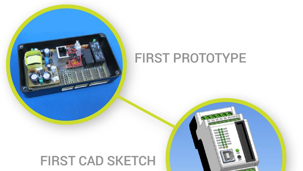
Many here will rightly argue that PLC standards are nice, but this PLC stands as a PLC, and from Arduin and Shilds you can assemble a system much cheaper for your needs. I will not argue, I did it myself and everything worked. It looked something like the photo of the prototype of the hero of the article on the kickstarter page .
On the other hand, I know a lot of those who caught fire with the capabilities of the Arduino platform, bought them, blinked with LEDs and ... threw them on it. Having mastered the basics of programming, they suddenly realized that they needed an order of magnitude more time to deal with electronics, bring everything to mind and assemble the finished product. Suddenly it turns out that your time is really worth the money and you do not want to spend it with no visible prospects.
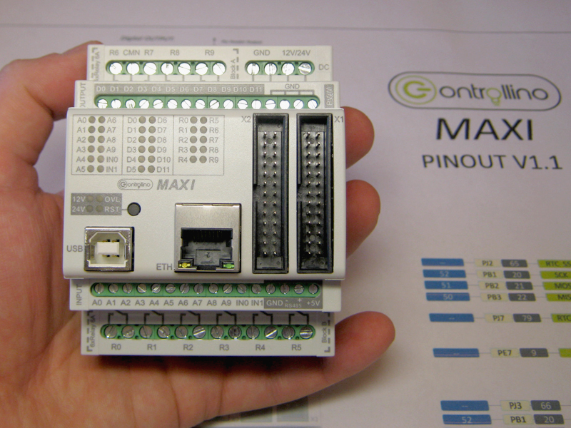
In my opinion, CONTROLLINO will be of interest to those Arduinschik, who can not or do not want to independently make TLC PLC for home automation, and instead is ready to buy a finished product. Moreover, CONTROLLINO has everything to use in the 'smart home': 34 I / O points, several communication interfaces and the ability to control all this from the Internet.
In the end, CONTROLLINO is just beautiful.
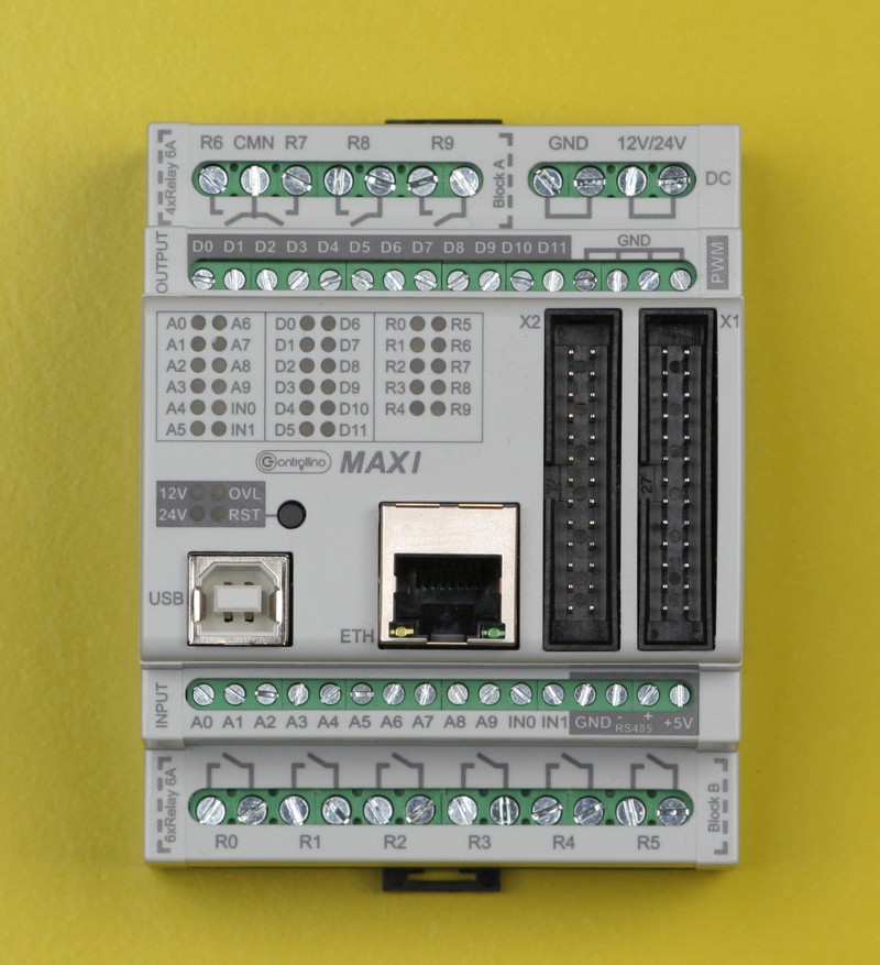

Remove the cover.
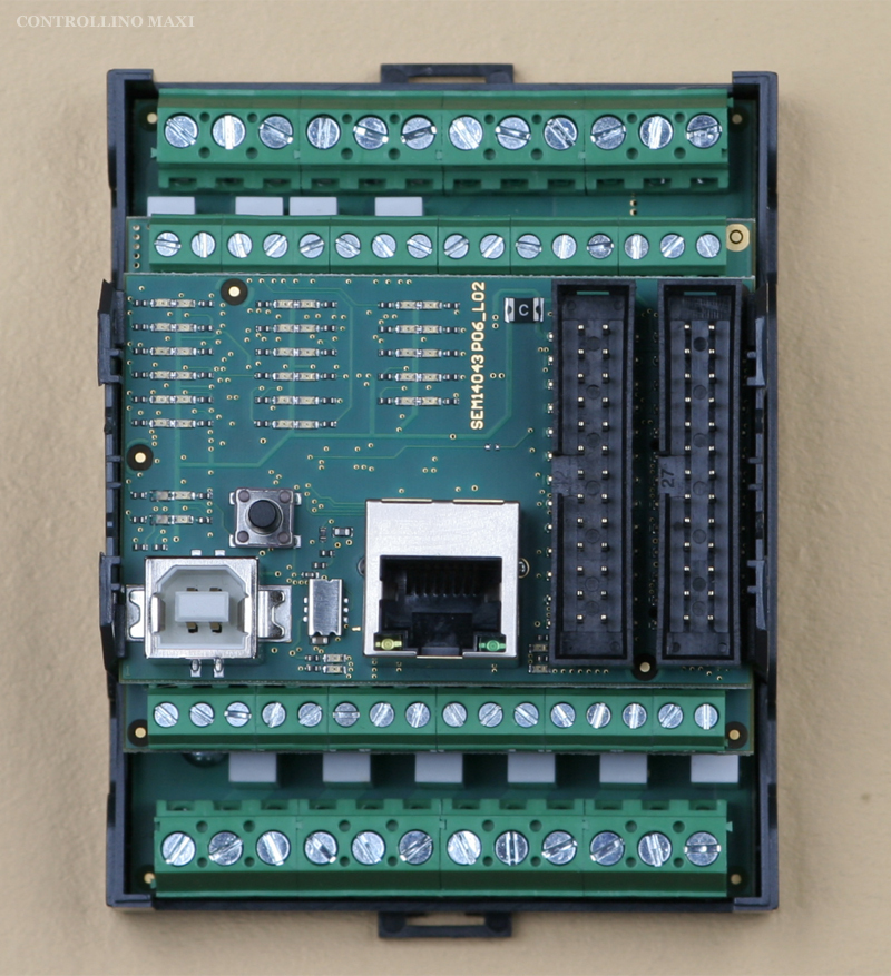
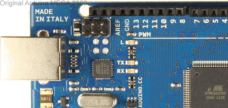
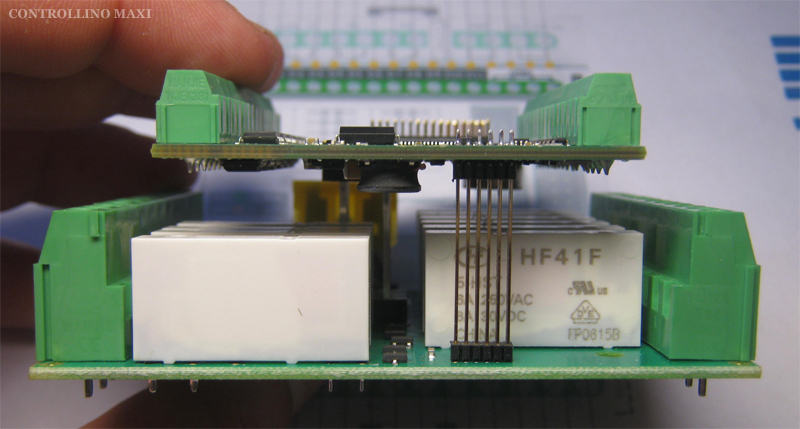
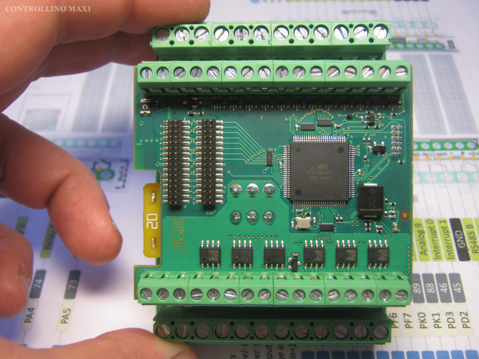
Inside the case are 3 boards. We take out the top. We see the good old chip W5100, which provides the Ethernet. There is also an atmega16 microprocessor. Not that I was surprised. I have already observed PLC with several microprocessors, for example, in models of the firm OWEN. But what is this processor doing here? It turned out all simple, he is responsible for downloading via USB. In the same way as in the original Italian Arduino MEGA 2560 board . You, like me, most likely have a Chinese clone, and in it there is a usual usb / rs232 converter on the boot. The middle and lower boards of CONTROLLINO MAXI are soldered to each other, alas. On the bottom 'relay' board, the HF41F relays are visible at ~ 250V / 6A. The average fee can only look on one side.

We see the ATmega2560 microprocessor and the binding of the inputs and outputs.
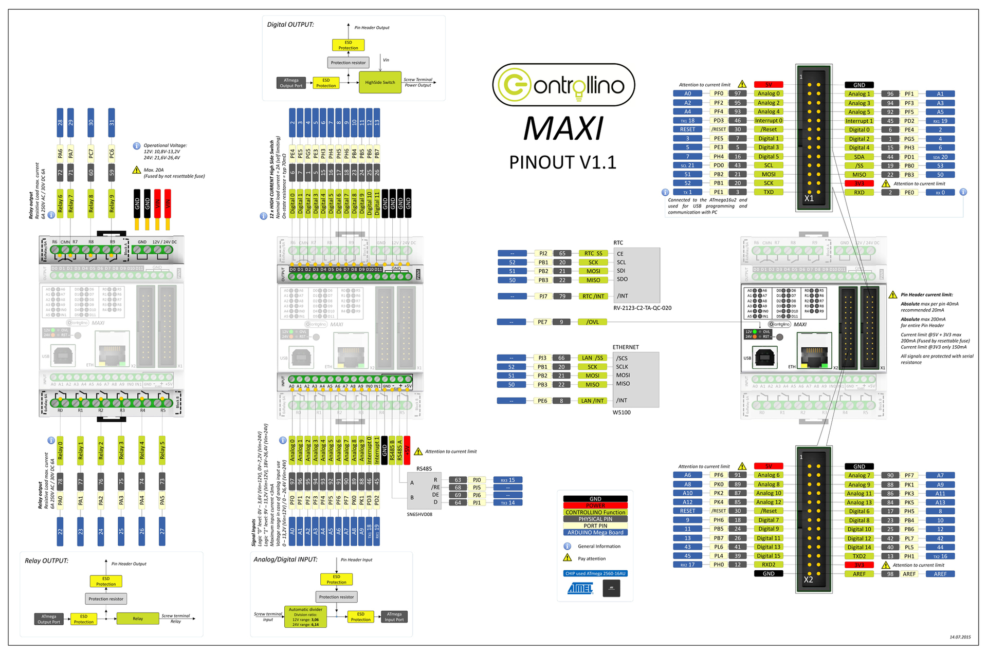
In order to find the correspondence of the inputs and outputs of CONTROLLINO to the pins of the Arduino MEGA 2560 board, the developer drew a large circuit. The names of the PLC terminals are marked yellow, and the names of the Arduino Mega 2560 pins are blue. For example, the R0 relay on the PLC corresponds to pin 22 of the Arduino Mega 2560. To close the R0 relay, you need to write such instructions in the sketch:

But this is the topic of the next article.
Universal inputs
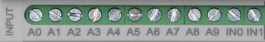
12 inputs, each can be considered in the program as analog or discrete. Two of them, IN0 and IN1, can be used as interrupt inputs.
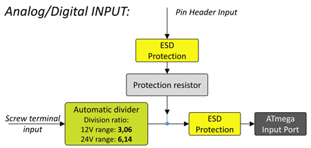
The analog inputs are volt, their range depends on the supply voltage of the PLC. If the PLC operates at 12V, then the analog signals have a range of 0 ... 13.2V. If the PLC operates from 24V, then the range of analog signals is 0 ... 26.4V. ADC 10 bit.
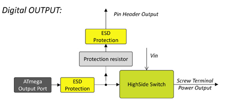
Transistor outputs
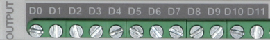
12 discrete transistor outputs, each can be used as PWM.
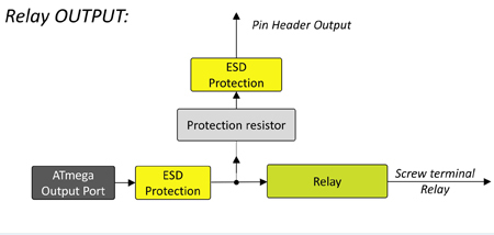
Relay outputs
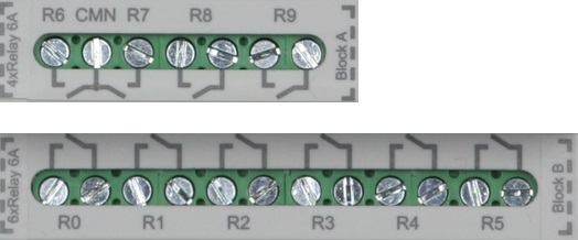
Relay HF41F to ~ 250V / 6A. 6 Ampere somehow not enough. I will assume that such relays were chosen because they are narrow and they can be more placed in a small area.
Nonvolatile real time clock
As a real-time clock (RTC), the DS1307 chip, which is familiar to arduinschikas, which operates on the I2C bus, is not used here. Here the RV-2123-C2-TA-QC-020 chip with SPI interface works for hours.
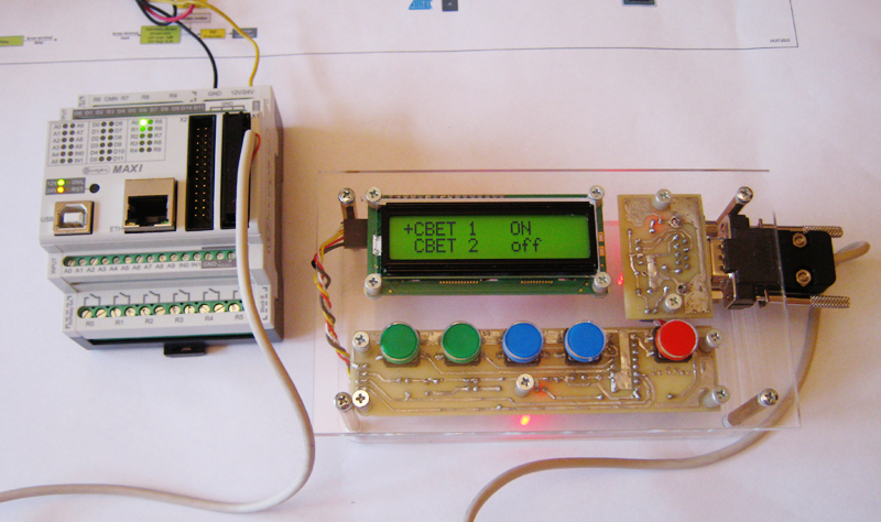
In general, of the three additional chips (Ethernet, RS-485 and RTC), two of CONTROLLINO work on the SPI bus and none on I2C. This convenient 'square' bus is completely free to connect user devices, such as my homemade operator panel with I2C bus .
Look at the RTC wiring diagram and note the dashes in the blue boxes.
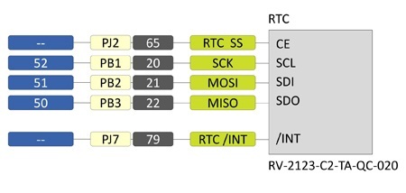
The dashes mean that the ATmega2560 microprocessor legs that are not connected to the Arduino MEGA 2560 pins are connected to the corresponding pins of the microcircuit. . Such a schematic solution has its advantages and disadvantages when programming (which is more a question), which I will write about in the next part.
RS-485
No modern PLC can do without an RS-485 port and CONTROLLINO is no exception. To do this, it is installed chip SN65HVD08.

RS-485 can operate in both master and slave mode.
Ethernet
At last the familiar microcircuit! The W5100 chip has already become synonymous with the concept of an arduino connection to the Internet. It is the W5100 that provides the Ethernet interface to CONTROLLINO.
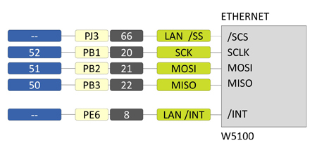
The fact that the Arduino 4 leg is not connected to the SCS contact, as is customary in standard connection schemes, but the next 'dash', does not complicate programming - all the examples work without problems.
Experimenting with Ethernet, I deployed a web server to CONTROLLINO, and managed this PLC via a smartphone using the Blynk android application.
Connectors X1 and X2
Some microcontroller signals are output not only to the terminals in the form of inputs and outputs with appropriate piping, but also directly to the two 26-pin connectors X1 and X2 through protective resistors.
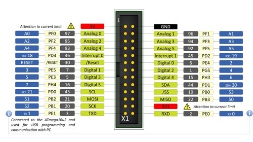
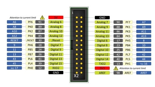
Some signals of the microprocessor are displayed both on the terminals and on the connectors, some are only on the terminals, and some on the connectors only. For example, the SPI and I2C interfaces are output only to the connector, the relay output signals R0 ... R9 are only at the terminals, and the analog inputs A0 ... IN1 are both at the connectors and at the terminals.
Of course, the same signal on the terminal and the connector is connected and used in different ways. For example, the universal inputs A0 ... IN1 can be programmed as outputs in the program and use them as such via the connector, but they cannot work via the output terminal; the binding will interfere.
Connectors X1 and X2 make the use of PLC more flexible, allowing you to connect modules that are used to use arduinschiki in their crafts. For example, DTH22 sensors or chips operating on a square bus.
So I made an operator panel that works on I2C and connects to CONTROLLINO via connector X1.
That's all about iron. In the next part I will talk about the programming features of the CONTROLLINO PLC, how to control it via the Internet from a smartphone from anywhere in the world, how the CONTROLLINO works on ModbusRTU and about many other things.
Links
→ Official site CONTROLLINO
→ Page on the kickstarter
→ Facebook project
→ RV-2123SPI RTC
→ SN65HVD08 RS-485
→ HF41F Relay
That guy worked as a php programmer and C ++ was not a problem for him. He had money and ideas, but there was no desire to study LAD or Codesys. As a result, he unsubscribed that he made a pre-order for CONTROLLINO and did not contact me anymore.
I do not know what and how it happened in the end, but after 3 years I had a chance to work with this device.
While I was creaking, I realized that there would be a lot of material. Therefore, the story about CONTROLLINO will be divided into two parts: the first will be about iron, the second about programming.
At the moment, there are 4 models of CONTROLLINO: MINI, MAXI, MAXI-AUTOMATION and MEGA. I worked with MAXI.
Brief characteristics of CONTROLLINO MAXI:
- ATmega2560 microprocessor
- 12 universal digital / analog inputs
- 12 transistor outputs, can work in PWM mode
- 10 relay outputs ~ 250V / 6A
- Non-Volatile RTC
- Ethernet
- RS-485
- SPI, I2C, 2xRS-232 TTL
- Power supply 12 or 24V DC
- Dimensions 72x90x62mm
- DIN rail enclosure
- Software compatible with Arduino MEGA 2560
CONTROLLINO and ARDUINO
First of all, I must say that CONTROLLINO is not an Arduino in a case with terminals instead of pins, as some might think.
CONTROLLINO is a programmable logic controller, PLC. That is, the finished product used in automation, with appropriate protection of inputs and outputs. The CONTROLLINO design with the Arduino as such (that is, with the debug board based on the atmega chip) is made only by the microprocessor used.
If you disassemble the CONTROLLINO (and we analyze), then inside we will not find the arduin welded to the Chinese shields or, even worse, simply the arduin with the wires twisted on the terminals.
Compatibility is provided at the level of software- CONTROLLINO MAXI can be programmed from the Arduino IDE as an Arduino MEGA 2560 board. And there and there the same ATmega2560 processor.
Many here will rightly argue that PLC standards are nice, but this PLC stands as a PLC, and from Arduin and Shilds you can assemble a system much cheaper for your needs. I will not argue, I did it myself and everything worked. It looked something like the photo of the prototype of the hero of the article on the kickstarter page .
On the other hand, I know a lot of those who caught fire with the capabilities of the Arduino platform, bought them, blinked with LEDs and ... threw them on it. Having mastered the basics of programming, they suddenly realized that they needed an order of magnitude more time to deal with electronics, bring everything to mind and assemble the finished product. Suddenly it turns out that your time is really worth the money and you do not want to spend it with no visible prospects.
Hello Dima!
Живущий в другом регионе одногруппник, открыл замечательный стартап. Вооружившись передовыми наработками из интернета, он перебрался за город и построил самогонный аппарат с большой производительностью. И все хорошо, продукт получался отменным(с его слов, я мало что в этом понимаю). Но технологический процесс длился 48 часов, в течении которых нужно по времени что-то включить, что-то выключить, отвинтить, закрутить и т.д. Спать доводилось урывками по два-три часа.
Естественно, возникла идея автоматизировать производство. Обратился ко мне за советом, я ему рассказал про ПЛК и все такое. А через время набирает меня и говорит, что купил замечательную штуку, Ардуино называется. Уже помигал светодиодами- в ардуине язык си, а он его не забыл еще с того времени, как мы учились на компьютерщиков. Осталось дело за малым: прикупить шилдов, что-то спаять самому и тогда выведет производство на новый уровень.
Но прошел год, два, еще сколько-то, а дальше светодиодов дело не пошло. Хотя, может быть мешает новое увлечение- пчеловодство.
In my opinion, CONTROLLINO will be of interest to those Arduinschik, who can not or do not want to independently make TLC PLC for home automation, and instead is ready to buy a finished product. Moreover, CONTROLLINO has everything to use in the 'smart home': 34 I / O points, several communication interfaces and the ability to control all this from the Internet.
In the end, CONTROLLINO is just beautiful.
Design
Remove the cover.
Inside the case are 3 boards. We take out the top. We see the good old chip W5100, which provides the Ethernet. There is also an atmega16 microprocessor. Not that I was surprised. I have already observed PLC with several microprocessors, for example, in models of the firm OWEN. But what is this processor doing here? It turned out all simple, he is responsible for downloading via USB. In the same way as in the original Italian Arduino MEGA 2560 board . You, like me, most likely have a Chinese clone, and in it there is a usual usb / rs232 converter on the boot. The middle and lower boards of CONTROLLINO MAXI are soldered to each other, alas. On the bottom 'relay' board, the HF41F relays are visible at ~ 250V / 6A. The average fee can only look on one side.
We see the ATmega2560 microprocessor and the binding of the inputs and outputs.
In order to find the correspondence of the inputs and outputs of CONTROLLINO to the pins of the Arduino MEGA 2560 board, the developer drew a large circuit. The names of the PLC terminals are marked yellow, and the names of the Arduino Mega 2560 pins are blue. For example, the R0 relay on the PLC corresponds to pin 22 of the Arduino Mega 2560. To close the R0 relay, you need to write such instructions in the sketch:
voidsetup() {
  pinMode(22, OUTPUT);
}
voidloop() {
  digitalWrite(22, HIGH);
  }
But this is the topic of the next article.
Universal inputs
12 inputs, each can be considered in the program as analog or discrete. Two of them, IN0 and IN1, can be used as interrupt inputs.
The analog inputs are volt, their range depends on the supply voltage of the PLC. If the PLC operates at 12V, then the analog signals have a range of 0 ... 13.2V. If the PLC operates from 24V, then the range of analog signals is 0 ... 26.4V. ADC 10 bit.
Transistor outputs
12 discrete transistor outputs, each can be used as PWM.
Relay outputs
Relay HF41F to ~ 250V / 6A. 6 Ampere somehow not enough. I will assume that such relays were chosen because they are narrow and they can be more placed in a small area.
Nonvolatile real time clock
As a real-time clock (RTC), the DS1307 chip, which is familiar to arduinschikas, which operates on the I2C bus, is not used here. Here the RV-2123-C2-TA-QC-020 chip with SPI interface works for hours.
In general, of the three additional chips (Ethernet, RS-485 and RTC), two of CONTROLLINO work on the SPI bus and none on I2C. This convenient 'square' bus is completely free to connect user devices, such as my homemade operator panel with I2C bus .
Look at the RTC wiring diagram and note the dashes in the blue boxes.
The dashes mean that the ATmega2560 microprocessor legs that are not connected to the Arduino MEGA 2560 pins are connected to the corresponding pins of the microcircuit. . Such a schematic solution has its advantages and disadvantages when programming (which is more a question), which I will write about in the next part.
RS-485
No modern PLC can do without an RS-485 port and CONTROLLINO is no exception. To do this, it is installed chip SN65HVD08.
RS-485 can operate in both master and slave mode.
Ethernet
At last the familiar microcircuit! The W5100 chip has already become synonymous with the concept of an arduino connection to the Internet. It is the W5100 that provides the Ethernet interface to CONTROLLINO.
The fact that the Arduino 4 leg is not connected to the SCS contact, as is customary in standard connection schemes, but the next 'dash', does not complicate programming - all the examples work without problems.
Experimenting with Ethernet, I deployed a web server to CONTROLLINO, and managed this PLC via a smartphone using the Blynk android application.
Connectors X1 and X2
Some microcontroller signals are output not only to the terminals in the form of inputs and outputs with appropriate piping, but also directly to the two 26-pin connectors X1 and X2 through protective resistors.
Some signals of the microprocessor are displayed both on the terminals and on the connectors, some are only on the terminals, and some on the connectors only. For example, the SPI and I2C interfaces are output only to the connector, the relay output signals R0 ... R9 are only at the terminals, and the analog inputs A0 ... IN1 are both at the connectors and at the terminals.
Of course, the same signal on the terminal and the connector is connected and used in different ways. For example, the universal inputs A0 ... IN1 can be programmed as outputs in the program and use them as such via the connector, but they cannot work via the output terminal; the binding will interfere.
Connectors X1 and X2 make the use of PLC more flexible, allowing you to connect modules that are used to use arduinschiki in their crafts. For example, DTH22 sensors or chips operating on a square bus.
So I made an operator panel that works on I2C and connects to CONTROLLINO via connector X1.
That's all about iron. In the next part I will talk about the programming features of the CONTROLLINO PLC, how to control it via the Internet from a smartphone from anywhere in the world, how the CONTROLLINO works on ModbusRTU and about many other things.
Links
→ Official site CONTROLLINO
→ Page on the kickstarter
→ Facebook project
→ RV-2123SPI RTC
→ SN65HVD08 RS-485
→ HF41F Relay