Creation of full-fledged applications on Max 7. Part 1 - Statement of the problem, visual programming
- Tutorial
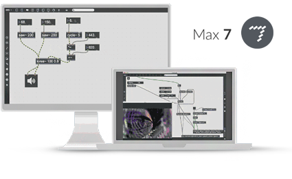 When solving the problems of information visualization, obviously, the question arises of the practical implementation of the plan. This series of articles is devoted to the process of designing applications using visual programming in Max 7 from Cycling '74. Let's start studying the issue, from simple to complex. We will go from amateur preparation to a full-fledged “single-file” application (standalone .exe).
 Level: Easy
♞
Final result
 Surely someone is using a program and does not realize that it was made using Max. Such a program, for example, is DAW Ableton Live. You can guess by the interface of the objects, as well as because of Max for Live. Of course, in such serious projects, not only Max is used, but also additional libraries, files, scripts, etc. Also, some modern programs on the iPad for working with sound. In this series of articles, we will try to understand the process of designing such complex applications, starting with the simplest examples.
Table of contents
 1. Visual programming
→ 1.1. Concepts
2. Interface Max 7
3. The principle of building programs in Max
→ 3.1. Modular objects with inputs and outputs
→ 3.2. Encapsulation [p patchname]
→ 3.3. Self-patch
→ 3.4. [bpatcher]
4. The structure of the program
→ 4.1. Project space
→ 4.2. First steps
→ 4.3. Bang, Metro, Counter, Number
→ 4.4. Get rid of excess
→ 4.5. Other objects
→ 4.6. Logical operators, regular expressions
→ 4.7. Logical expressions
5. Useful modules
Attached files
Useful links
♞
§ 1. Visual programming
Visual programming is a way of creating a computer program by manipulating graphic objects instead of writing its text. [1]

This programming method will allow the reader to move away from writing lines of code in languages like C / C ++, everything is presented in the form of modules and the relationships between them. The development process becomes more visual and faster, while the program runs in real time while you are doing it, i.e. for any changes in the structure, the result is displayed immediately, without compilation. In fact, you are building a logical flowchart of the program.
To solve visualization problems, we will use the visual programming language - Max (MSP). Basically, Max is designed to create interactive art objects, but can also be used to solve a huge layer of problems. In many areas, you can find something that can be visualized beautifully. Remember these spy movies in which various beautiful interfaces of unknown programs are depicted on the computers of heroes. And in reality - for example, visualization of information coming from sensors. In addition, it allows you to develop both on machines running Windows and on computers running Mac OS.
§ 1.1. The concepts
To describe the implementation process, we introduce the following concepts:
- An object is an element of a program that performs any operations or displays information. May or may not have input and output values.
- A module is a group of objects combined into a sub-patch in order to perform a given task.
- Patch, sub - patch - in Max 7, the source files of the program under development are saved in the format .maxpatch, .maxhelp or .json and are called patches. A sub-patch, in turn, is a child of the patch; it can be stored both in a separate file and inside the patch.
- Inlet - an object that creates the switching of modules with each other. It is the input parameter of the module.
- Outlet [outlet] - an object that creates the switching modules with each other. This is the output value of the module.
- Module input - the place of connection of external objects with the module, input parameters.
- Module output - the place of connection of external objects with the module, sends the output of the module to the output.
In terms of telecommunications, the module acts as a switch, which in turn performs the specified functions and sends the result to the output ports.
§ 2. Interface Max 7
Note. In this article I will try not to delve into the obvious things. A lot of additional information about the operation of objects and modules is available in the help - right-click on the object, then "Open object_name help". Therefore, when describing program elements, preference will be given mainly to their purpose, rather than syntax or structure.
Basically we will use the following modes: constructor and presentation, as well as look in the console windows (Max console), object inspector (Inspector, CTRL + I) and patch inspector (Inspector Window, CTRL + SHIFT + I).
- The main menu of the program
- [inlet] objects. Module inputs
- Components (objects) of the module, the executable part.
- [outlet] objects. Module outputs.
- Inspector. Parameters of the selected object.
- Lock / unlock patch editing.
- Switch between designer and presentation modes.
- On / off grid.
- Program area.
§ 3. The principle of building programs in Max
§ 3.1. Modular objects with inputs and outputs
 The process of creating programs comes down to building a block diagram of the modules and the relationships between them. You can use the modules built into Max, but the most interesting thing is to write them yourself. This is very convenient both when calling them from within the program, and when used in the programming process as a whole. In ordinary programming, this model is presented in the form of OOP, well, or you can imagine one module as one function, the parameters of which are the inputs of the module, and return is the output, and there can be many outputs.
 Note: To add an object to the patch, click 2 times with the mouse on an empty space, or press the N key, enter a name, press Enter and then you can already connect it with others.
There are several ways to add self-written modules:
- encapsulation [p patchname],
- standalone patch,
- [bpatcher].
§ 3.2. Encapsulation [p patchname]
 This concept is similar to the concept of encapsulation in ordinary programming languages. In this case, everything is elementary - select the objects that we want to combine into a group / module / file and press CTRL + E (Edit - Encapsulation). When encapsulation is completed in this way, the output is a module - [p patchname], where patchname is any phrase in English. Numeric characters are also available.
After the completion of this process, the objects to be merged disappear from the Max patch window. In fact, Max inside the original patch creates a subpatcher, where it transfers all the selected objects and their connections. Depending on the presence of external connections, the encapsulator can automatically insert objects inlets and outlets, as well as connect them to external objects. This is very convenient when you develop a program without thinking about piling up objects, because when you reach a certain amount, the structure of the program will cease to be readable and you yourself will get confused in it. To solve the problems of organizing the structure of the program, encapsulation in Max is designed.
 Features :it is a tool for grouping / delimiting objects according to various criteria. This method of creating modules implies the uniqueness of each module. Those. if you create one module in this way and duplicate it - these will already be two different modules. Making changes to one of them will not entail a change in the remaining duplicates.
 Application : unique groups of objects, simple or complex calculations that are used in the program in only one place.
§ 3.3. Stand alone patch
 To create modules, you can use another way. It is enough to create a new file, add and connect the necessary blocks, place the objects responsible for accepting the input [inlet], and for sending to the output - [outlet] and save the file in any folder (for example, create a separate folder “tools” and throw patches there with its prefix). Next, in the working patch, add the object with the name [file_name] (without the permission of the .maxpat file) and you're done.
  This method can be used in combination with the encapsulation described above. It is even more convenient. You can encapsulate the necessary objects, open the resulting module (in the locked mode, double-click the block with the left mouse button) and save it as an independent patch.
 Features :A convenient thing for creating modules of the “black box” type is that once we write a module, we will no longer return without the need for its structure, etc. We see only 3 types of information: inputs, module name and outputs. It is important that when duplicating such modules, their content does not become unique, i.e. changes in one of the duplicates will entail changes in all of them. More precisely, in this case, not duplicate modules are edited, but the original module file itself.
Application : it is convenient to use this method when creating modules for any individual calculations. Features allow multiple duplicate modules.
A good example is the message translation module from decimal to binary. A simple copy-paste of the translator's abstraction objects inside the main patch in this case will be a sign of bad tone, because it may turn out that the module requires changes. It’s easier to change 1 file than iterate over all this copy-paste.
§ 3.4. [bpatcher]
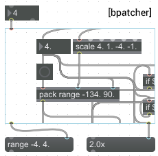 If in the previous methods we created “black boxes”, then there are times when you need to display any part of the module in open form without editing the structure. It can be various numerical visualizations, display of service messages, etc. Even more interesting is the process of adding the presentation part of the module.
 This method expands the scope of application of independent patches. In order to add a module to the working patch, just create an object [bpatcher], and in the inspector of its properties specify the path to the module file.
Features : we can see the structure and connections of the module, as well as the presentation part.
Application :suitable for organizing the top level of the program structure, i.e. in fact, we display grouped modules with one object, which is very convenient - we get rid of unnecessary heaps of wires and auxiliary objects. We see only those parts that are needed.
§ 4. Program structure
 The whole process of writing a program will be reduced to numerous encapsulations and the addition of subpatches to the working patch. This is quite logical and convenient, especially when designing complex programs, where there can be many modules of various applications. In fact, we simply dig in the “workhorses” of the program into groups deeper and deeper, and at the exit we will have an elementary structure of just a few objects. If you need to make changes to any of the modules, then we simply open its file and do it without any problems.
 For me personally, this way of designing programs is more visual. In addition, you do not need to duplicate a bunch of character code, and in some cases it is very tiring.
Visual examples of modules created by the above methods are presented in the tut01_subpatches.maxpat file
§ 4.1. Design space
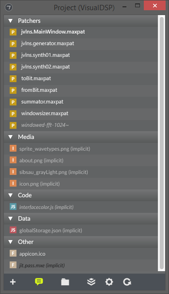 To create complex programs with a large number of libraries, Max 7 provides the ability to create projects. This function is presented as a list of patches and other files used in the project. The thumbnail on the right shows the contents of an already completed major project for the visualization of digital signal processing. As you can see, in the list we see not only the .maxpat patch files themselves, but also other types of files.
 In the future, it will be possible to use such a list “for yourself”, just to know where what lies and what modules are used in this project. Although, you can compile the program even from the main patch, even from the menu with the project. The difference is that when you open a project, you can set the default patch to be opened - you open the project and the assigned patch opens along with the list of files.
§ 4.2. First steps
We will begin our thorny journey of learning about programming in the Max 7 environment by creating a new project. File → New Project. It is recommended to save all projects in a separate folder, for example, C: \ Max Projects \ ... The location of the project folder in the root of the disk is extremely convenient, especially when changing the version of the program or OS.
 After saving the project, a window opens with a list of project patches, but so far it is empty. Add a new file to the project:
 + → Add New File ... Save the file to the directory where the project file is located, and then Max will create the patchers folder there, in which the patch file is actually saved.
§ 4.3. Bang, Metro, Counter, Number
Let's start with something simple, such as a counter with a clock. The counter will add a value by one only when a bang message from the clock generator (metronome) arrives at the counter input.
Bang is a special message that starts a module / object. The completion of any operation in the module on the output gives some value, while the fact of sending data from the module to its output is accompanied by a bang message. Bang is used when you need to send a message somewhere. He, as it were, “pushes” the message further along the path from object to object.
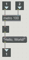
 Add objects and links to our patch as in the image on the right.
 Note.Max is also good because patches can be easily exchanged in text format. This happens as follows - you select all the elements and links in the patch by pressing CTRL + A, copy CTRL + C, and then open any text editor or form on the site and paste the text from the clipboard. In fact, the description of the program state (structure, data) is presented in the form of the JSON text that you just copied. Reading such information is not much more difficult: in the main menu Max 7 Files → New From Clipboard ... In general, it is not even necessary to create a new file, you can paste the copied directly into an already open patch. Thus, Max reads the text from the clipboard and interprets it into modules and the relationships between them.
Try copying the program code below and paste into Max.
Tut_lesson01 module code
{
	"patcher" : 	{
		"fileversion" : 1,
		"appversion" : 		{
			"major" : 7,
			"minor" : 0,
			"revision" : 2,
			"architecture" : "x64",
			"modernui" : 1
		}
,
		"rect" : [ 458.0, 167.0, 574.0, 390.0 ],
		"bglocked" : 0,
		"openinpresentation" : 0,
		"default_fontsize" : 12.0,
		"default_fontface" : 0,
		"default_fontname" : "Arial",
		"gridonopen" : 1,
		"gridsize" : [ 15.0, 15.0 ],
		"gridsnaponopen" : 1,
		"objectsnaponopen" : 1,
		"statusbarvisible" : 2,
		"toolbarvisible" : 1,
		"lefttoolbarpinned" : 0,
		"toptoolbarpinned" : 0,
		"righttoolbarpinned" : 0,
		"bottomtoolbarpinned" : 0,
		"toolbars_unpinned_last_save" : 0,
		"tallnewobj" : 0,
		"boxanimatetime" : 200,
		"enablehscroll" : 1,
		"enablevscroll" : 1,
		"devicewidth" : 0.0,
		"description" : "",
		"digest" : "",
		"tags" : "",
		"style" : "",
		"subpatcher_template" : "",
		"boxes" : [ 			{
				"box" : 				{
					"id" : "obj-21",
					"maxclass" : "comment",
					"numinlets" : 1,
					"numoutlets" : 0,
					"patching_rect" : [ 265.0, 165.0, 30.0, 20.0 ],
					"style" : "",
					"text" : "в)"
				}
			}
, 			{
				"box" : 				{
					"id" : "obj-20",
					"maxclass" : "comment",
					"numinlets" : 1,
					"numoutlets" : 0,
					"patching_rect" : [ 145.0, 165.0, 30.0, 20.0 ],
					"style" : "",
					"text" : "б)"
				}
			}
, 			{
				"box" : 				{
					"id" : "obj-19",
					"maxclass" : "comment",
					"numinlets" : 1,
					"numoutlets" : 0,
					"patching_rect" : [ 25.0, 165.0, 30.0, 20.0 ],
					"style" : "",
					"text" : "a)"
				}
			}
, 			{
				"box" : 				{
					"id" : "obj-13",
					"maxclass" : "number",
					"numinlets" : 1,
					"numoutlets" : 2,
					"outlettype" : [ "", "bang" ],
					"parameter_enable" : 0,
					"patching_rect" : [ 255.0, 135.0, 50.0, 22.0 ],
					"style" : ""
				}
			}
, 			{
				"box" : 				{
					"id" : "obj-14",
					"maxclass" : "newobj",
					"numinlets" : 5,
					"numoutlets" : 4,
					"outlettype" : [ "int", "", "", "int" ],
					"patching_rect" : [ 255.0, 90.0, 81.0, 22.0 ],
					"style" : "",
					"text" : "counter 2 0 3"
				}
			}
, 			{
				"box" : 				{
					"id" : "obj-15",
					"maxclass" : "number",
					"numinlets" : 1,
					"numoutlets" : 2,
					"outlettype" : [ "", "bang" ],
					"parameter_enable" : 0,
					"patching_rect" : [ 300.0, 15.0, 50.0, 22.0 ],
					"style" : ""
				}
			}
, 			{
				"box" : 				{
					"id" : "obj-16",
					"maxclass" : "newobj",
					"numinlets" : 2,
					"numoutlets" : 1,
					"outlettype" : [ "bang" ],
					"patching_rect" : [ 255.0, 60.0, 65.0, 22.0 ],
					"style" : "",
					"text" : "metro 500"
				}
			}
, 			{
				"box" : 				{
					"id" : "obj-17",
					"maxclass" : "toggle",
					"numinlets" : 1,
					"numoutlets" : 1,
					"outlettype" : [ "int" ],
					"parameter_enable" : 0,
					"patching_rect" : [ 255.0, 15.0, 24.0, 24.0 ],
					"style" : ""
				}
			}
, 			{
				"box" : 				{
					"id" : "obj-8",
					"maxclass" : "number",
					"numinlets" : 1,
					"numoutlets" : 2,
					"outlettype" : [ "", "bang" ],
					"parameter_enable" : 0,
					"patching_rect" : [ 135.0, 135.0, 50.0, 22.0 ],
					"style" : ""
				}
			}
, 			{
				"box" : 				{
					"id" : "obj-9",
					"maxclass" : "newobj",
					"numinlets" : 5,
					"numoutlets" : 4,
					"outlettype" : [ "int", "", "", "int" ],
					"patching_rect" : [ 135.0, 90.0, 81.0, 22.0 ],
					"style" : "",
					"text" : "counter 1 0 3"
				}
			}
, 			{
				"box" : 				{
					"id" : "obj-10",
					"maxclass" : "number",
					"numinlets" : 1,
					"numoutlets" : 2,
					"outlettype" : [ "", "bang" ],
					"parameter_enable" : 0,
					"patching_rect" : [ 180.0, 15.0, 50.0, 22.0 ],
					"style" : ""
				}
			}
, 			{
				"box" : 				{
					"id" : "obj-11",
					"maxclass" : "newobj",
					"numinlets" : 2,
					"numoutlets" : 1,
					"outlettype" : [ "bang" ],
					"patching_rect" : [ 135.0, 60.0, 65.0, 22.0 ],
					"style" : "",
					"text" : "metro 500"
				}
			}
, 			{
				"box" : 				{
					"id" : "obj-12",
					"maxclass" : "toggle",
					"numinlets" : 1,
					"numoutlets" : 1,
					"outlettype" : [ "int" ],
					"parameter_enable" : 0,
					"patching_rect" : [ 135.0, 15.0, 24.0, 24.0 ],
					"style" : ""
				}
			}
, 			{
				"box" : 				{
					"id" : "obj-7",
					"maxclass" : "number",
					"numinlets" : 1,
					"numoutlets" : 2,
					"outlettype" : [ "", "bang" ],
					"parameter_enable" : 0,
					"patching_rect" : [ 15.0, 135.0, 50.0, 22.0 ],
					"style" : ""
				}
			}
, 			{
				"box" : 				{
					"id" : "obj-6",
					"maxclass" : "newobj",
					"numinlets" : 5,
					"numoutlets" : 4,
					"outlettype" : [ "int", "", "", "int" ],
					"patching_rect" : [ 15.0, 90.0, 71.0, 22.0 ],
					"style" : "",
					"text" : "counter 0 3"
				}
			}
, 			{
				"box" : 				{
					"id" : "obj-5",
					"maxclass" : "number",
					"numinlets" : 1,
					"numoutlets" : 2,
					"outlettype" : [ "", "bang" ],
					"parameter_enable" : 0,
					"patching_rect" : [ 60.0, 15.0, 50.0, 22.0 ],
					"style" : ""
				}
			}
, 			{
				"box" : 				{
					"id" : "obj-4",
					"maxclass" : "newobj",
					"numinlets" : 2,
					"numoutlets" : 1,
					"outlettype" : [ "bang" ],
					"patching_rect" : [ 15.0, 60.0, 65.0, 22.0 ],
					"style" : "",
					"text" : "metro 500"
				}
			}
, 			{
				"box" : 				{
					"id" : "obj-3",
					"maxclass" : "toggle",
					"numinlets" : 1,
					"numoutlets" : 1,
					"outlettype" : [ "int" ],
					"parameter_enable" : 0,
					"patching_rect" : [ 15.0, 15.0, 24.0, 24.0 ],
					"style" : ""
				}
			}
 ],
		"lines" : [ 			{
				"patchline" : 				{
					"destination" : [ "obj-11", 1 ],
					"disabled" : 0,
					"hidden" : 0,
					"midpoints" : [ 189.5, 58.0 ],
					"source" : [ "obj-10", 0 ]
				}
			}
, 			{
				"patchline" : 				{
					"destination" : [ "obj-9", 0 ],
					"disabled" : 0,
					"hidden" : 0,
					"source" : [ "obj-11", 0 ]
				}
			}
, 			{
				"patchline" : 				{
					"destination" : [ "obj-11", 0 ],
					"disabled" : 0,
					"hidden" : 0,
					"source" : [ "obj-12", 0 ]
				}
			}
, 			{
				"patchline" : 				{
					"destination" : [ "obj-13", 0 ],
					"disabled" : 0,
					"hidden" : 0,
					"midpoints" : [ 264.5, 134.0 ],
					"source" : [ "obj-14", 0 ]
				}
			}
, 			{
				"patchline" : 				{
					"destination" : [ "obj-16", 1 ],
					"disabled" : 0,
					"hidden" : 0,
					"midpoints" : [ 309.5, 58.0 ],
					"source" : [ "obj-15", 0 ]
				}
			}
, 			{
				"patchline" : 				{
					"destination" : [ "obj-14", 0 ],
					"disabled" : 0,
					"hidden" : 0,
					"source" : [ "obj-16", 0 ]
				}
			}
, 			{
				"patchline" : 				{
					"destination" : [ "obj-16", 0 ],
					"disabled" : 0,
					"hidden" : 0,
					"source" : [ "obj-17", 0 ]
				}
			}
, 			{
				"patchline" : 				{
					"destination" : [ "obj-4", 0 ],
					"disabled" : 0,
					"hidden" : 0,
					"source" : [ "obj-3", 0 ]
				}
			}
, 			{
				"patchline" : 				{
					"destination" : [ "obj-6", 0 ],
					"disabled" : 0,
					"hidden" : 0,
					"source" : [ "obj-4", 0 ]
				}
			}
, 			{
				"patchline" : 				{
					"destination" : [ "obj-4", 1 ],
					"disabled" : 0,
					"hidden" : 0,
					"midpoints" : [ 69.5, 58.0 ],
					"source" : [ "obj-5", 0 ]
				}
			}
, 			{
				"patchline" : 				{
					"destination" : [ "obj-7", 0 ],
					"disabled" : 0,
					"hidden" : 0,
					"midpoints" : [ 24.5, 134.0 ],
					"source" : [ "obj-6", 0 ]
				}
			}
, 			{
				"patchline" : 				{
					"destination" : [ "obj-8", 0 ],
					"disabled" : 0,
					"hidden" : 0,
					"midpoints" : [ 144.5, 134.0 ],
					"source" : [ "obj-9", 0 ]
				}
			}
 ],
		"dependency_cache" : [  ],
		"embedsnapshot" : 0
	}
}
Let's take it in order. The main objects in this patch are:
3 clocks ([toggle] + [metro]) and 3 counters [counter].
[toggle]
Switch. It has two operating modes: button (Button) and switch (Toggle). When you click on [toggle], the object sends the value of its state [0, 1] to the output. When you press the "button", it sends a short unit to the output. The switch is different in that it remembers its previous state. Pressed once, at the output 0, again - 1, again - 0, etc.
[metro 500]
This object is a metronome that sends a bang message every N-milliseconds to its output. In this case, bang will be generated every 500 ms.
[counter direction min value max value]
A counter that adds its value by one unit for each bang message that arrives at the input. In the direction of reference, the counters are divided into ascending (a), descending (b) and round-trip (c).
Thus, the name of the object [counter 1 0 3] tells us about the descending counter with boundaries from 0 to 3. When the maximum value is reached, the counter is reset and the countdown starts from min. values. The object has two inlets, allowing you to reset the counter. One of them resets the value instantly, and the other - reset, starting from the next count.
[number]
Data entry object that allows you to store the entered information. It is used only for integers, for floating-point numbers there is an object [flonum].
§ 4.4. Get rid of excess
An important skill in creating programs is the ability to get rid of unnecessary details. An inquisitive reader would notice that in the above patch we use 3 clock generators and 3 switches, although you can use only one copy each. Looking ahead, I’ll say that the more objects of type [metro] you add, the slower the processing of other information by the program can become. To get a program with good performance, you should think about it at the initial stage.
Get rid of the excess, remove the redundant calculations from the program:
 We replace three clocks with one; we connect the inputs of the counters to the output of the object [metro 500]. That's better. You can say that you had to do this from the very beginning, but in practice the coordinates of the generator blocks and other objects can be very different, without hesitation you add another metronome, and then another and another. As a result, the connections of objects turn into a tangled web, which is quite difficult to navigate. With the right approach to these problems, you can avoid multiple encapsulations of objects in modules by grouping them according to their purpose. This is what we will achieve throughout the cycle of articles.
§ 4.5. Other objects
[print]
If for some reason you want to display information in the console, the [print line_name] object is used for this. The name of the object [print b] tells us that when a message arrives at the input [print], a message of the form b: text will be displayed in the console .
§ 4.6. Logical operators, regular expressions
Elementary operations
[+ i / f] - the addition of two values of the input parameters of the object with the return of the result to the outlet.
Note: [+ 1], [+ 1.06]. i -int - integers, f - float - floating point numbers.
[* i / f] - multiplication
[/ i / f] - division
[+ ~ 1.] - addition of two signals
[* ~ 1.] - multiplication of two signals
[if condition then 1 else 0] - when the condition is met, send to the output is one, otherwise zero.
[if condition then 1 else out2 0] - when the condition is met, send one to the first output, otherwise send zero to the second output.
[regexp] - work with regular expressions
[expr $ i1 + $ i2 * $ i3]- execute the expression between the values received at the input of the module.
The remaining operations are available in the documentation, everything is similar to conventional programming.
We save the above code as two different files with the names tobit.maxpat and frombit.maxpat in the project's patch folder. In the future, for the implementation of encoding / decoding of numbers, we will use these very modules.

§ 4.7. Logical expressions
Using the [vexpr] object, various logical operations can be defined.
tut_bitlogic.maxpat - in this example, bitwise logical operations of multi-bit messages are considered.
§ 5. Useful modules
Here I will list the modules that I use most often. He wrote some from scratch, some found on the tech support forum. There you can find a solution to almost any issue, rarely when I did not find something.
[toBit]
This module translates the numbers from 0 to 255 into an eight-bit bit code.
[fromBit]
Accepts an eight-bit bit code, and outputs numbers from 0 to 255.
[tut_dynamicInlets N]
An example of the organization of inputs and outputs with a given number N.
Attached Files
 tut_lesson01.maxpat tut_bitlogic.maxpat tut_encapsulation.maxpat tut_dynamicInlets.maxpat toBit.maxpat fromBit.maxpat All at once (.zip) + tutorial_all.maxpat directory
useful links
 Review article on the hub about Max MSP Cycling '74 - manufacturer's website / page Max 7. Max Objects Database - storage of various objects. Why reinvent the wheel when it is already there. Cycling '74 - Projects - projects of other developers. Cycling '74 - Forums - a forum where you can find solutions for many problems, just ask the right thing. Pattr.ru - here you can find useful buns and articles for Max MSP. maxmsp vk - a group of Russian-speaking users.
In the next issue
The list may change, an example option:
- § Forms and methods for entering information
- § Charts, GUI
- § Opening HTML pages
- § Creation of external links
- § Ways. PATH =?
- § Calling an external module (window) using a button
♞
Author: Valery Zimnev