Artificial dawn
It all started a year ago. Before the New Year 2014, vitality somewhat declined. The process of self-digging led to the following thought:
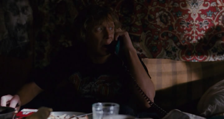
- Well, so dark, Lord? © Radio Day.
However, for a person living in the summertime in summertime - the thought is quite natural.
Unable to rearrange the time, I decided to try to change the sensations by changing the lighting. The train of thought was approximately the following: natural light enters the apartment naturally through a window, and when there is no light, it is dark. It is difficult to turn on the light outside the window, but you can create the illusion that there is light outside. Looking at the window at night we see the darkness - this cannot be changed, but at night people usually turn on the light and close the curtains - it is so lighter and more comfortable. And what is the difference between a curtained window at night and day? And the fact that light breaks through the curtains. So, in fact, the very idea was born: it is necessary to highlight the space between the window and the curtains!
For a general basic verification of the concept, a white LED strip was bought and glued (it turned out that there was an adhesive layer on these tapes) to the kitchen ledge, and in such a way that the LEDs themselves could not be seen even by accident - this is an illusion, it cannot be destroyed. Of course, I am aware that there is a lot of an element of psychology here - but it really worked.
The necessary 2A for 12V white five-meter tape were taken were taken from the PSU of a dead portable disk. However, 12V from a computer PSU will be no worse (you just need to know how to start it and you should not turn it on completely without load).
Unfortunately, only three pictures from that first historical experiment (shot on a mixer) were preserved, but I think they convey a general idea.

Yes ...well, a messin general, so-so ... But! Let's not forget that it is evening. But in the winter morning, and in the summertime - it is very invigorating!
Inspired by the first luck, I decided to continue the experiment now not on myself, but on my own children. After all, it is one thing to get up on an alarm clock yourself and it is quite another to wake up unfortunate children to school when you cannot see one; knowing perfectly well that one of them is like a lark who, if it were light outside, would have been sitting at the table for a long time and quietly collecting some LEGO ... But, here - of course, we need a real illusion . Need a dawn! Present. And not at 7 in the morning when dad turned on (dad, too, by the way, would have slept again). And not immediately, but gradually. And the light should not be white, but red-orange-yellow.
Obviously, we need a scheduled RGB tape. And that means a microcontroller and a real-time clock. And the free time that appeared successfully coincided with the already existing desire to do something useful on AVR.
Ta dam. Meet - Voskhod1b! A device to simulate natural dawn, it’s a gentle alarm clock, it’s an organizer, it’s a night lamp, it’s all you need if you add the necessary sensors and modify the code. For example: an assembly traffic light, an office clock with an indication of lateness and breaks, or an illumination for an aquarium or light and music decoration, etc., etc.
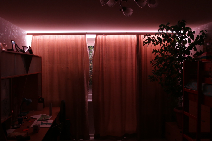
Dawn
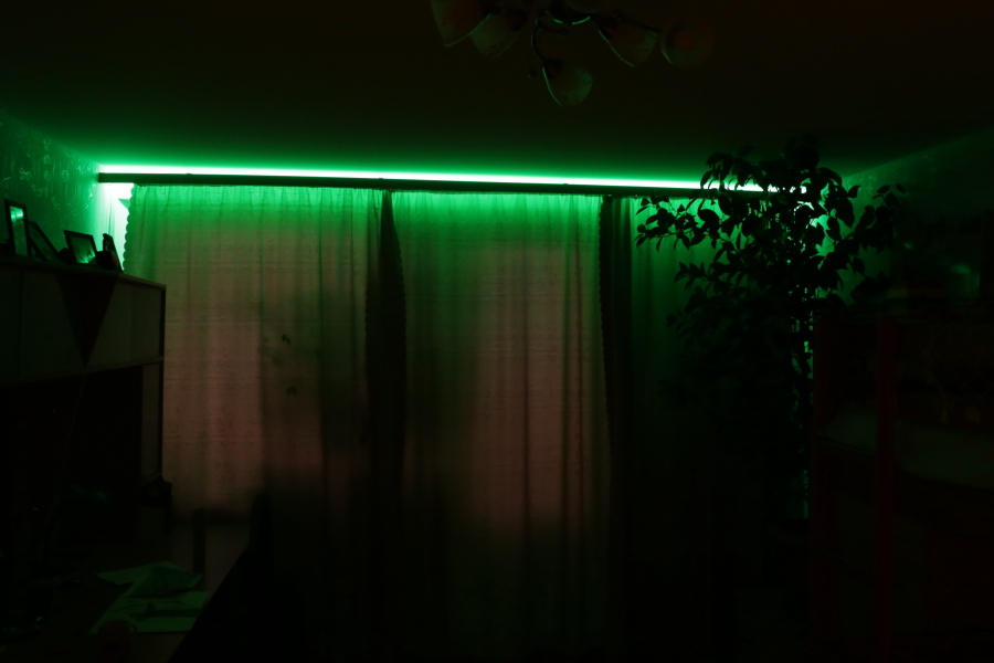
Children get ready for school (the so-called 'green whistle')


Daylight, extend the 'sunny 'day

nightlight
The schedule is programmed using a text interface. Available commands can be obtained by requesting a hint with the command - h, possible schedule modes can be found with the command - ha. You can connect either directly via UART or via bluetooth. Colors are encoded in three hexadecimal bytes. To select color values, it is possible to use the interactive mode. In interactive mode, you can control both RGB and HSV color components. Schedule is stored in the controller EEPROM memory. The device can be turned off at any time. The state after switching on is 'as if it did not turn off'.
Here is an example of a timetable that I used for my third-year-
students exhausted by the school a year ago: 00:00:00 => 06:40:00: dark sleep
06:40:00 => 06:55:00: rgb 08 05 03artificial -...
06:55:00 => 07:00:00: rgb 40 25 15 ... ny ...
07:00:00 => 07:05:00: rgb 80 50 39 ... sunrise
07:05: 00 => 07:55:00: rgb ff 91 1d warm white light
07:55:00 => 08:00:00: rgb 00 55 00 5 minutes before going to school - 'green whistle'
08:00:00 = > 08:05:00: rgb 55 55 00 we go to school - the 'yellow whistle'
08:05:00 => 08:20:00: rgb 55 00 00 we are already late for school - the 'red whistle'
08:20:00 => 11:00:00: dark children at school
11:00:00 => 13:30:00: rgb ff 91 1d warm white
13:30:00 => 14:30:00: rgb 80 50 39 small daytime ...
14:30:00 => 15:00:00:rgb 20 12 07 ... backlight
15:00:00 => 16:57:00: dark daytime sleep
16:57:00 => 16:58:00: rgb 20 12 07 millet -...
16:58:00 => 16:59:00 : rgb 40 25 14 ... share -...
16:59:00 => 17:00:00: rgb 80 50 30 ...
sa 17:00:00 => 21:00:00: rgb ff 91 1d evening illumination
21 : 00: 00 => 22:00:00: rgb 40 25 15 artificial ...
22:00:00 => 23:00:00: rgb 08 05 03 ... sunset
23:00:00 => 23:30: 00: rgb 01 01 03 twilight
23:30:00 => 00:00:00: rgb 00 00 01 night before midnight
Scheme :
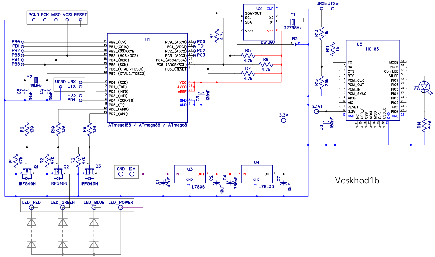
Used MK ATmega168. ATmega328 or ATmega88 / ATmega8 will do, but the latter will have a bit less commands and a shorter hint. I did not check, but I am sure that ATmega16 will work. Real time clock - DS1307. LEDs are lit by MOSFETs of the IRF540N. Of course, such powerful transistors are not needed, they were just at hand, but common and not expensive - it’s not a pity. There is a margin of power, you can work with 24V tapes, and if there is current protection in the power supply, short circuits in the tape are not terrible.
The necessary 5V for mega and 3.3V for the HC-05 bluetooth module are produced by the linear stabilizers L7805 and L78L33. The bluetooth module (U5) is optional, as are the resistors R11, R12, R13 (matching 5V MK with 3.3V of the bluetooth controller) as a stabilizer U4. The circuit will start and work even without U2, but, of course, only in interactive mode.
Program.I didn’t want to write in assembler, apparently that’s why the program did not fit into ATtiny2313, and I didn’t really bother. It was interesting to evaluate the possibility of using C ++ for programming microcontrollers. It turned out that it was quite possible, using abstract interfaces, to write code compiled for both MK (Atmel Studio 6.1) and Windows (Microsoft Visual Studio 2012). Under Windows, the project is built using the RTC, UART, EEPROM, and PWM emulation program. I am sure that the code will be compiled without problems under Linux as well, if you exclude the only windows-api function SetConsoleTitleA (), which displays the current PWM values in the window title.
The library for working with UART is taken from Application Note AVR303 - buffered hardware UART on interrupts. The code is slightly modified to support ATmega8 / 16, ATmegaX8 and ATiny2313 (USART2.сpp, USART2.h).
To work with the I2C interface DS1307, the library of Pavel Bobkov ChipEnable.Ru is used (for which many thanks to him) based in turn on AVR315 (twim.cpp, twim.h).
Hmm, it turns out that the project is assembled "from the world on a thread." However, why be surprised - the way it is. Of what I can brag about myself, this is perhaps the implementation of the fast HSV-> RGB conversion, in which the division operation is not used (see HSV2RGB.cpp, HSV2RGB.h).
Work with UART and I2C is done by interruptions, and so that the processor does not get bored: PWM - software. That is, almost software - tied to an 8-bit timer. The experiments showed that a purely software PWM in the main loop, despite the maximum frequency, looks bad, flickers. I suspect that the reason is associated with small frequency fluctuations that become visible to the eye. My PWM, though programmatic, is not entirely simple: the LEDs light up with a shift by a third of the period. For example, if R = G = B = 25, then the periods of glow of the LEDs are R [0.24], G [85.109], B [170.194]. According to my feelings, in this mode of operation, the tape looks better.
Printed circuit boardDivorced in the DipTrace program on one layer. The size of the PP is determined by the size of the purchased plastic box. I had to put transistors and stabilizers, but I had to refuse convenient clamping sockets - there was not enough space.
Power supply unit - any one suitable for power to power LED strips. For a regular five-meter 12-volt RGB tape (60 LEDs per meter), you need a 6A power supply. Of course, a computer PSU is also suitable. If you use the PSU from a computer, there is no need for stabilizers U3, U4, since 5V and 3.3V can be taken directly from it. There are only two drawbacks to a computer PSU: size and fan.
Schematic diagram, drawing of a printed circuit board (there is a version for LUT and a version for LUT with fill), source code, firmware for ATMega8 / 88/168/328 and a windows emulator are attached.
The programming process and various options for programmers are not considered here. I use the usbasp programmer: www.fischl.de/usbasp
And the program: www.khazama.com/project/programmer/KhazamaAVRProgrammer162.rar
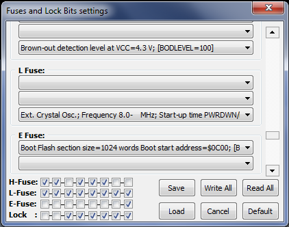
About fuzy. Factory AtmegaX8s are sold with the “Divide clock by 8 internally” bit set, which must be removed. You also need to reconfigure MK to use high-frequency quartz and be sure to use the "Brown-out detector level at VCC = 4.3V", otherwise there may be problems with the contents of the EEPROM. In the khazama AVR Programmer, the fuses used look like this:

Fiberglass shavings are a very harmful thing, it is advisable to minimize their quantity. To cut the workpiece, I recommend not using a hacksaw, but scissors for metal - this is more accurate, faster, and much more convenient. It is better to drill textolite under a layer of water, but this is a bit later.
The LUT circuit board is our everything. Photoprocess - I didn’t try until there was a need for such delicate productions as to tinker with UV lamps and evil alkalis. So, LUT. A lot of things have been tried: a lot of glossy magazines, and the notorious photo paper of a well-known company of various densities and foil (it’s scary to put it in the printer, but it really works), BUT my current choice is vinyl film.

Purchased in the household, cheap. Need a smooth, textured is not suitable, the color does not matter. Well, what a delight that is! We print the PP drawing on paper, cut off a piece of vinyl film to the size of the drawing, glue it on the drawing on top, print again. We cut it out, iron it with a iron, cool it under a press (an inverted stool is suitable) and just gently remove the film from the board. Once again - you don’t need to soak and roll anything - just slowly tear off it like scotch tape. As a demonstration, my board is flooded with fine mesh, in the original LUT technology, removing paper from the holes is very troublesome.

Yes, the board must first be cleaned from oxide and degreased. Fans can, of course, use fine skins and acetone, but my choice, and for a long time already, is powder Comet and paper towels for drying.
Poisonin a completely safe solution of citric acid in hydrogen peroxide. At room temperature, the process takes 15 minutes. Everything happens without spots and smell, like from ferric chloride. (100 ml of hydrogen peroxide, 40 g of citric acid, 1 teaspoon of salt). At the end, the solution is safely drained into the sewer.

Drill , as already mentioned, in a tub of water. By the way, the megarelles in the photograph are made of just two motors from an inkjet printer.
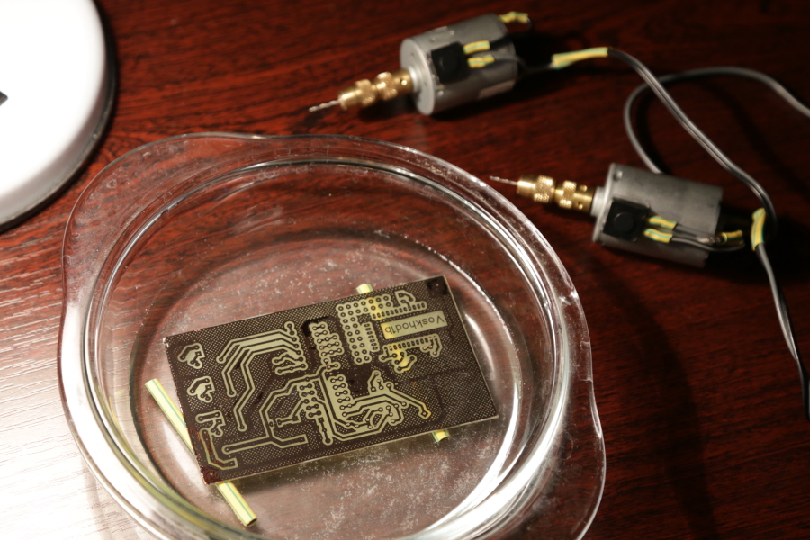


Pay attention to the turbidity - some of this dust could be in the lungs.
Toner removal is done without chemicals. Acetone? No, not heard. A metal washcloth can remove toner in less than a minute.


Tinning.Good old soldering iron is already fed up. Like this eternal question, what is tinned or drilled before? Tinning with ROSE alloy in water with citric acid and salt. The process takes several minutes. No glycerin! And no rubber spatulas - it’s uncomfortable and hot. My choice is a paint brush and wooden sticks to fix the board on the bottom of the dish. Citric acid removes an oxide film from the surface of the board. Salt is needed to raise the boiling point, and water and salt boil somehow calmer.
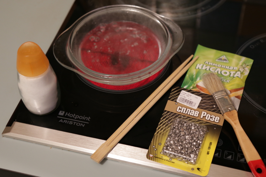
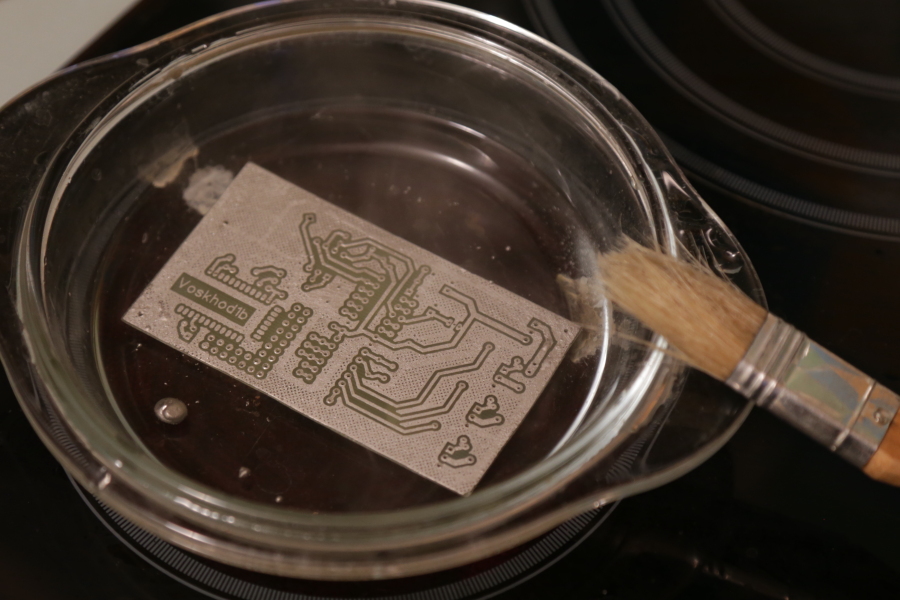
Naturally, tinning utensils should not be used for food.
After tinning, the board is washed, dried (paper towels) and covered with a layer of liquid flux (rosin in alcohol).
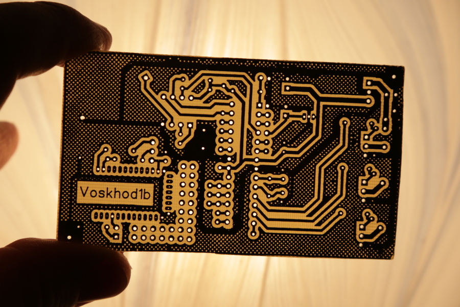
What a beauty!
As they say in such cases -“a well-fixed patient does not need anesthesia”"A properly assembled circuit does not need to be set up." However, I can recommend some assembly order: we install all the resistors and capacitors, sockets for microcircuits and stabilizers U3, U4. We supply power and make sure that on pin 7 MK 5V, and 3.3V is also in place. Next, we install transistors, quartz, connect the LED strip and program the MK either on the board or in the programmer, and put it in place. After powering up, the LEDs on the tape should pass through all the colors for 5 seconds from red through green and blue to red. If the process of changing colors takes 20 seconds, the fusion “Divide clock by 8 internally” is most likely incorrectly installed. Then we connect via UART (9600/8 data / no parity / 1 stop) and play with colors in an interactive mode. Set DS1307, set the time with the ts command and make sure that the clock goes ... or does not go ??? There is a subtle point: the DS1307 does not always start. Do not panic, wash off the flux, dry the board, try to pull the quartz body to the ground, change the quartz, or at worst the DS1307 itself. The clock microchip is very sensitive, it actually works at microcurrents - a little accuracy and everything will work out.
We attach the tape to the cornice and / or ceiling - the main thing is that only the light from the diodes would be visible, and not the diodes themselves.
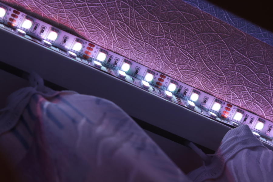
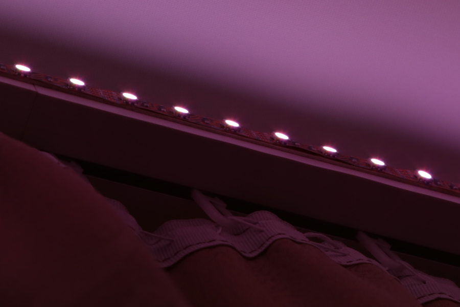
It is convenient to make the connection of the tape with the board with a usual twisted pair, brown and brown with white - 12V, the other colors, respectively - R, G, B. If you use the bluetooth module, you can fix it somewhere on the ledge, then you only have to pull 12V or 220V if place the power supply in the same place.
About the bluetooth module - HC-05 - the handkerchief is shallow and for installation it is convenient to first solder the legs to it, and then install it on the board.

Assembled device :
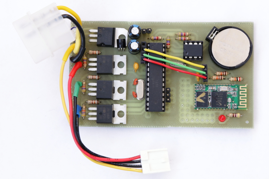
Pay attention to the jumpers. They connect the bluetooth module to the microcontroller: 3.3V - 3.3V1; URX - UTXb; UTX - URXb. If the blutooth module is not used, the UART adapter is connected to the URX, UTX, GND sockets.
And yes, I confess, I put the power regulator of the bluetooth module on its sideoh, ugly like that - I myself do not like it just to fit the Molex connector into the box.

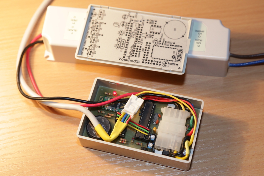
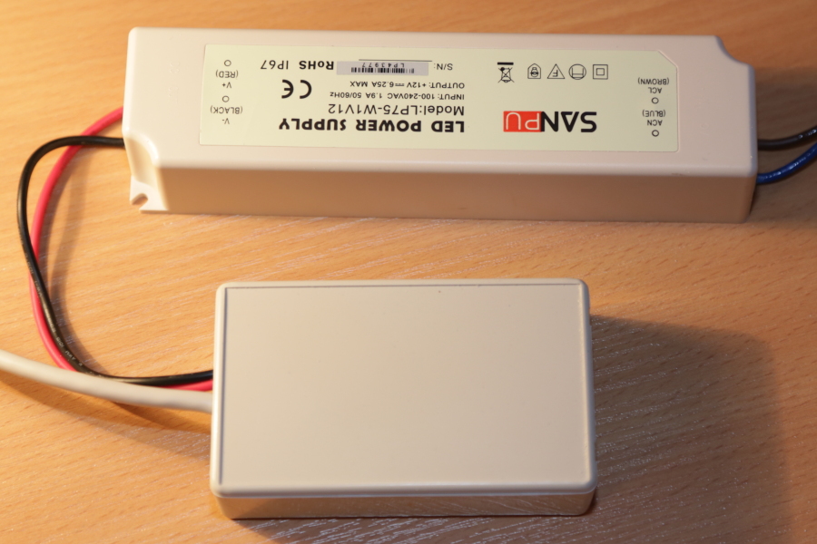
Scheme, firmware, board, source
There are two devices in operation. The latter is compiled exactly according to the attached documentation. It works 24 * 5.5 - because on the weekend, despite the general concept, everyone wants to sleep. Dad played with AVR, drilled his son, soldered and now joyfully steers a tape from the tablet. In general, everyone is happy.
Thanks for attention. I hope the device will be useful to someone.
- Well, so dark, Lord? © Radio Day.
However, for a person living in the summertime in summertime - the thought is quite natural.
Idea
Unable to rearrange the time, I decided to try to change the sensations by changing the lighting. The train of thought was approximately the following: natural light enters the apartment naturally through a window, and when there is no light, it is dark. It is difficult to turn on the light outside the window, but you can create the illusion that there is light outside. Looking at the window at night we see the darkness - this cannot be changed, but at night people usually turn on the light and close the curtains - it is so lighter and more comfortable. And what is the difference between a curtained window at night and day? And the fact that light breaks through the curtains. So, in fact, the very idea was born: it is necessary to highlight the space between the window and the curtains!
For a general basic verification of the concept, a white LED strip was bought and glued (it turned out that there was an adhesive layer on these tapes) to the kitchen ledge, and in such a way that the LEDs themselves could not be seen even by accident - this is an illusion, it cannot be destroyed. Of course, I am aware that there is a lot of an element of psychology here - but it really worked.
The necessary 2A for 12V white five-meter tape were taken were taken from the PSU of a dead portable disk. However, 12V from a computer PSU will be no worse (you just need to know how to start it and you should not turn it on completely without load).
Unfortunately, only three pictures from that first historical experiment (shot on a mixer) were preserved, but I think they convey a general idea.
Yes ...
Inspired by the first luck, I decided to continue the experiment now not on myself, but on my own children. After all, it is one thing to get up on an alarm clock yourself and it is quite another to wake up unfortunate children to school when you cannot see one; knowing perfectly well that one of them is like a lark who, if it were light outside, would have been sitting at the table for a long time and quietly collecting some LEGO ... But, here - of course, we need a real illusion . Need a dawn! Present. And not at 7 in the morning when dad turned on (dad, too, by the way, would have slept again). And not immediately, but gradually. And the light should not be white, but red-orange-yellow.
Obviously, we need a scheduled RGB tape. And that means a microcontroller and a real-time clock. And the free time that appeared successfully coincided with the already existing desire to do something useful on AVR.
Implementation
Ta dam. Meet - Voskhod1b! A device to simulate natural dawn, it’s a gentle alarm clock, it’s an organizer, it’s a night lamp, it’s all you need if you add the necessary sensors and modify the code. For example: an assembly traffic light, an office clock with an indication of lateness and breaks, or an illumination for an aquarium or light and music decoration, etc., etc.
Dawn
Children get ready for school (the so-called 'green whistle')
Daylight, extend the 'sunny 'day
nightlight
The schedule is programmed using a text interface. Available commands can be obtained by requesting a hint with the command - h, possible schedule modes can be found with the command - ha. You can connect either directly via UART or via bluetooth. Colors are encoded in three hexadecimal bytes. To select color values, it is possible to use the interactive mode. In interactive mode, you can control both RGB and HSV color components. Schedule is stored in the controller EEPROM memory. The device can be turned off at any time. The state after switching on is 'as if it did not turn off'.
Here is an example of a timetable that I used for my third-year-
students exhausted by the school a year ago: 00:00:00 => 06:40:00: dark sleep
06:40:00 => 06:55:00: rgb 08 05 03artificial -...
06:55:00 => 07:00:00: rgb 40 25 15 ... ny ...
07:00:00 => 07:05:00: rgb 80 50 39 ... sunrise
07:05: 00 => 07:55:00: rgb ff 91 1d warm white light
07:55:00 => 08:00:00: rgb 00 55 00 5 minutes before going to school - 'green whistle'
08:00:00 = > 08:05:00: rgb 55 55 00 we go to school - the 'yellow whistle'
08:05:00 => 08:20:00: rgb 55 00 00 we are already late for school - the 'red whistle'
08:20:00 => 11:00:00: dark children at school
11:00:00 => 13:30:00: rgb ff 91 1d warm white
13:30:00 => 14:30:00: rgb 80 50 39 small daytime ...
14:30:00 => 15:00:00:rgb 20 12 07 ... backlight
15:00:00 => 16:57:00: dark daytime sleep
16:57:00 => 16:58:00: rgb 20 12 07 millet -...
16:58:00 => 16:59:00 : rgb 40 25 14 ... share -...
16:59:00 => 17:00:00: rgb 80 50 30 ...
sa 17:00:00 => 21:00:00: rgb ff 91 1d evening illumination
21 : 00: 00 => 22:00:00: rgb 40 25 15 artificial ...
22:00:00 => 23:00:00: rgb 08 05 03 ... sunset
23:00:00 => 23:30: 00: rgb 01 01 03 twilight
23:30:00 => 00:00:00: rgb 00 00 01 night before midnight
Scheme :
Used MK ATmega168. ATmega328 or ATmega88 / ATmega8 will do, but the latter will have a bit less commands and a shorter hint. I did not check, but I am sure that ATmega16 will work. Real time clock - DS1307. LEDs are lit by MOSFETs of the IRF540N. Of course, such powerful transistors are not needed, they were just at hand, but common and not expensive - it’s not a pity. There is a margin of power, you can work with 24V tapes, and if there is current protection in the power supply, short circuits in the tape are not terrible.
The necessary 5V for mega and 3.3V for the HC-05 bluetooth module are produced by the linear stabilizers L7805 and L78L33. The bluetooth module (U5) is optional, as are the resistors R11, R12, R13 (matching 5V MK with 3.3V of the bluetooth controller) as a stabilizer U4. The circuit will start and work even without U2, but, of course, only in interactive mode.
Program.I didn’t want to write in assembler, apparently that’s why the program did not fit into ATtiny2313, and I didn’t really bother. It was interesting to evaluate the possibility of using C ++ for programming microcontrollers. It turned out that it was quite possible, using abstract interfaces, to write code compiled for both MK (Atmel Studio 6.1) and Windows (Microsoft Visual Studio 2012). Under Windows, the project is built using the RTC, UART, EEPROM, and PWM emulation program. I am sure that the code will be compiled without problems under Linux as well, if you exclude the only windows-api function SetConsoleTitleA (), which displays the current PWM values in the window title.
The library for working with UART is taken from Application Note AVR303 - buffered hardware UART on interrupts. The code is slightly modified to support ATmega8 / 16, ATmegaX8 and ATiny2313 (USART2.сpp, USART2.h).
To work with the I2C interface DS1307, the library of Pavel Bobkov ChipEnable.Ru is used (for which many thanks to him) based in turn on AVR315 (twim.cpp, twim.h).
Hmm, it turns out that the project is assembled "from the world on a thread." However, why be surprised - the way it is. Of what I can brag about myself, this is perhaps the implementation of the fast HSV-> RGB conversion, in which the division operation is not used (see HSV2RGB.cpp, HSV2RGB.h).
Work with UART and I2C is done by interruptions, and so that the processor does not get bored: PWM - software. That is, almost software - tied to an 8-bit timer. The experiments showed that a purely software PWM in the main loop, despite the maximum frequency, looks bad, flickers. I suspect that the reason is associated with small frequency fluctuations that become visible to the eye. My PWM, though programmatic, is not entirely simple: the LEDs light up with a shift by a third of the period. For example, if R = G = B = 25, then the periods of glow of the LEDs are R [0.24], G [85.109], B [170.194]. According to my feelings, in this mode of operation, the tape looks better.
Printed circuit boardDivorced in the DipTrace program on one layer. The size of the PP is determined by the size of the purchased plastic box. I had to put transistors and stabilizers, but I had to refuse convenient clamping sockets - there was not enough space.
Power supply unit - any one suitable for power to power LED strips. For a regular five-meter 12-volt RGB tape (60 LEDs per meter), you need a 6A power supply. Of course, a computer PSU is also suitable. If you use the PSU from a computer, there is no need for stabilizers U3, U4, since 5V and 3.3V can be taken directly from it. There are only two drawbacks to a computer PSU: size and fan.
Schematic diagram, drawing of a printed circuit board (there is a version for LUT and a version for LUT with fill), source code, firmware for ATMega8 / 88/168/328 and a windows emulator are attached.
The programming process and various options for programmers are not considered here. I use the usbasp programmer: www.fischl.de/usbasp
And the program: www.khazama.com/project/programmer/KhazamaAVRProgrammer162.rar
About fuzy. Factory AtmegaX8s are sold with the “Divide clock by 8 internally” bit set, which must be removed. You also need to reconfigure MK to use high-frequency quartz and be sure to use the "Brown-out detector level at VCC = 4.3V", otherwise there may be problems with the contents of the EEPROM. In the khazama AVR Programmer, the fuses used look like this:
A little about some technological aspects of electronic production of PP at home
Fiberglass shavings are a very harmful thing, it is advisable to minimize their quantity. To cut the workpiece, I recommend not using a hacksaw, but scissors for metal - this is more accurate, faster, and much more convenient. It is better to drill textolite under a layer of water, but this is a bit later.
The LUT circuit board is our everything. Photoprocess - I didn’t try until there was a need for such delicate productions as to tinker with UV lamps and evil alkalis. So, LUT. A lot of things have been tried: a lot of glossy magazines, and the notorious photo paper of a well-known company of various densities and foil (it’s scary to put it in the printer, but it really works), BUT my current choice is vinyl film.
Purchased in the household, cheap. Need a smooth, textured is not suitable, the color does not matter. Well, what a delight that is! We print the PP drawing on paper, cut off a piece of vinyl film to the size of the drawing, glue it on the drawing on top, print again. We cut it out, iron it with a iron, cool it under a press (an inverted stool is suitable) and just gently remove the film from the board. Once again - you don’t need to soak and roll anything - just slowly tear off it like scotch tape. As a demonstration, my board is flooded with fine mesh, in the original LUT technology, removing paper from the holes is very troublesome.
Yes, the board must first be cleaned from oxide and degreased. Fans can, of course, use fine skins and acetone, but my choice, and for a long time already, is powder Comet and paper towels for drying.
Poisonin a completely safe solution of citric acid in hydrogen peroxide. At room temperature, the process takes 15 minutes. Everything happens without spots and smell, like from ferric chloride. (100 ml of hydrogen peroxide, 40 g of citric acid, 1 teaspoon of salt). At the end, the solution is safely drained into the sewer.
Drill , as already mentioned, in a tub of water. By the way, the megarelles in the photograph are made of just two motors from an inkjet printer.
Pay attention to the turbidity - some of this dust could be in the lungs.
Toner removal is done without chemicals. Acetone? No, not heard. A metal washcloth can remove toner in less than a minute.
Tinning.Good old soldering iron is already fed up. Like this eternal question, what is tinned or drilled before? Tinning with ROSE alloy in water with citric acid and salt. The process takes several minutes. No glycerin! And no rubber spatulas - it’s uncomfortable and hot. My choice is a paint brush and wooden sticks to fix the board on the bottom of the dish. Citric acid removes an oxide film from the surface of the board. Salt is needed to raise the boiling point, and water and salt boil somehow calmer.
Naturally, tinning utensils should not be used for food.
After tinning, the board is washed, dried (paper towels) and covered with a layer of liquid flux (rosin in alcohol).
What a beauty!
Assembly
As they say in such cases -
We attach the tape to the cornice and / or ceiling - the main thing is that only the light from the diodes would be visible, and not the diodes themselves.
It is convenient to make the connection of the tape with the board with a usual twisted pair, brown and brown with white - 12V, the other colors, respectively - R, G, B. If you use the bluetooth module, you can fix it somewhere on the ledge, then you only have to pull 12V or 220V if place the power supply in the same place.
About the bluetooth module - HC-05 - the handkerchief is shallow and for installation it is convenient to first solder the legs to it, and then install it on the board.
Assembled device :
Pay attention to the jumpers. They connect the bluetooth module to the microcontroller: 3.3V - 3.3V1; URX - UTXb; UTX - URXb. If the blutooth module is not used, the UART adapter is connected to the URX, UTX, GND sockets.
And yes, I confess, I put the power regulator of the bluetooth module on its side
Growth points
- SMD
- different schedules by day of the week
- hardware PWM
- light sensor
- other actuators
- GUI
- ARM32 - especially interesting (several STM32F030F4P6 are waiting for their time)
Scheme, firmware, board, source
Total
There are two devices in operation. The latter is compiled exactly according to the attached documentation. It works 24 * 5.5 - because on the weekend, despite the general concept, everyone wants to sleep. Dad played with AVR, drilled his son, soldered and now joyfully steers a tape from the tablet. In general, everyone is happy.
Thanks for attention. I hope the device will be useful to someone.