Electrofocuser based on Arduino Uno debug board, part 2
Continuation, the beginning here.
In order not to solve the problem in a very general way, I asked myself certain requirements based on general considerations (budget, simplicity or complexity of component purchase, difficulty in implementation or expected problems in operation). At the same time, the presentation of these considerations will allow you to immediately translate a possible dialogue into a constructive direction, and for those who want to use my experience, they will tell you what details you need to pay attention to. So let's get started.
The solution should be:
The main functions of the device:
Based on the method of application, it is necessary to have at least two options for controlling the focusing device:
When working remotely with a PC, I want to be able to memorize the position of the focuser in the same way and go to the given position. This is due to the fact that when changing the eyepiece, the focal length changes and the focusing procedure must be carried out again. I would like to save the focuser positions for each eyepiece in the form of presets and quickly switch between them when changing the eyepiece. Of course, you will have to refocus the telescope, but this can not be avoided in any case, since at different temperatures the focal length may differ slightly. Based on this, the firmware of the microcontroller should take steps (considering the microstep mode) and transfer the current position to the PC, as well as scroll the focuser to the specified position.
The motor is unambiguously stepping, since most of the time the focuser is stationary, rotation is required at low revolutions, with accurate focusing, rotation is required to the smallest possible angle, and most of the time rigid position fixation is required - the stepping motor is ideal for solving this problem.
An extremely important parameter by which you need to choose an engine is the required engine torque . In my case, the maximum torque that I managed to fix was ~ 2 kg / cm at room temperature.
Wanting to have some margin, I set a minimum torque of 3 kg / cm.
The next important parameter is positioning accuracy. Since I have already decided that I will use a stepper motor, the question is: what step should the motor have and should I use a driver with microstep support? Most available engines have a step of 1.8 ° per revolution (or 200 steps), but models with a step of 0.9 ° (400 steps per revolution), 7.5 ° and others are also available. This parameter is also individual. In my case, the focus area was about 15 °.
As a result, I came to the conclusion that you can use a stepper motor with a pitch of 1.8 ° or 0.9 °, but in any case you need a stepper motor driver with micro-step support. For this reason, I had to abandon the use of popular drivers distributed as Arduino Shield - all of them do not support microsteps. The choice fell on the easily accessible and cheap Polulu A4988 , which really had to be placed on a separate board.
Later, in the next project, I used the DRV8825 of the same manufacturer and I liked it much more.
 "
"
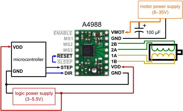
To control the A4988, you need at least 6 signals - ENABLE, STEP, DIR and three microstep selection signals MS1, MS2, MS3. Considering the three buttons on the remote control (left, right and “release”) and the speed LED, it turns out that you have to use 10 digital outputs of the microcontroller.
Arduino Uno is powered by a fairly wide voltage range (recommended range of 7-12V) and low current, so when choosing a power source, you actually have to push it away from the engine. The A4988 driver supports voltages from 8 to 35V. Stepper motors are presented in a wide range, with different rated parameters (for different voltage and current). I would like to use a power source for both the control unit and the engine itself. From here we get a limitation: the supply voltage should be in the range of 8-12V. The final choice can be made after the choice of engine is made based on the required power.
In addition, it is worth considering the place of use of the telescope. In my case, this is a loggia (~ 220V), roof of the house (battery), on the road (car, 12V or ~ 220V through an inverter, but sometimes you have to leave the car and then again the battery). Perhaps someone should immediately choose a battery instead of a power supply.
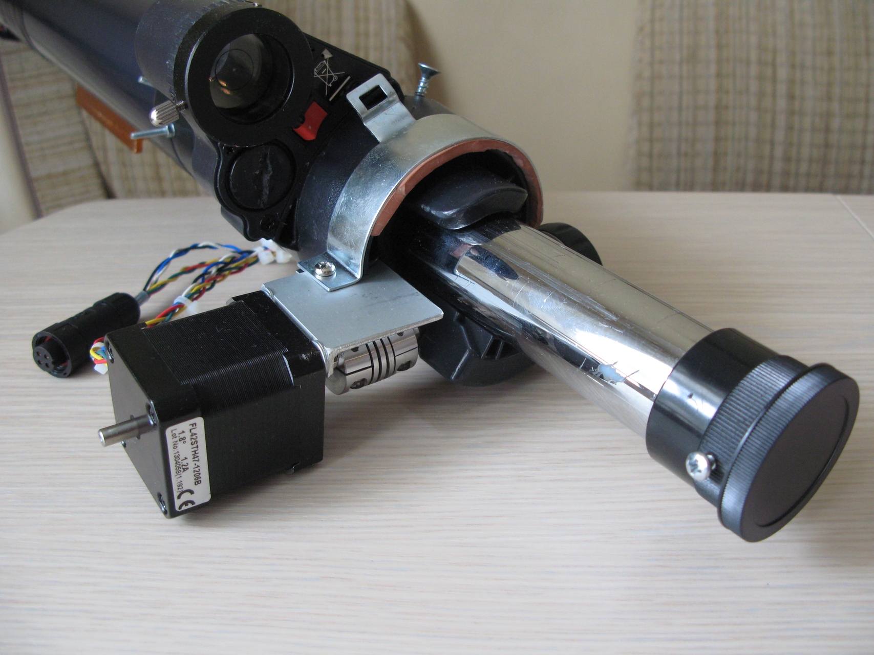
I chose the coaxial placement of the engine: with the help of a coupling, the engine is fixed directly on the shaft of the focusing device. The second fulcrum is an arbitrary rigid mount of the engine to the focuser body. Simple and reliable, although it requires more torque. Such a scheme will simplify the fastening as much as possible (one point), facilitate the removal and installation of the engine if necessary, and, most importantly, avoid the “alignment” of the mechanical part - mounting and fitting gears, pulleys, etc.
Scheme 1
Since the engine is placed on a focusing device on a telescope, weight is important. Too much weight will complicate the balancing, increase the load on the mount and tripod, dimensions - add windage. Therefore, the smaller the engine, the better. This criterion is quite individual, I asked the maximum engine weight of 300 g.
So, we have already determined that we need a stepper motor with certain
Next, launch a browser and look for a suitable engine on the Internet. The average cost in China is 10-20USD, the average cost in the Russian Federation is 1000-1500r. We try to choose an engine with the lowest rated current possible. Theoretically, you can use motors with a current of up to 2A, but a large current will lead to strong heating of the engine (it will have to be turned off every time after focusing) and fast battery consumption. In addition, the A4988 driver has a built-in current limiter, which is good, since it can connect a motor designed for significantly high currents. The bad news is that such an engine will not gain the desired torque.
To select a coupler, we need to know the bore diameters. To do this, we must measure the diameter of the focuser shaft and look at the diameter of the motor shaft. In my case, it turned out 8 mm and 5 mm, respectively. You will also need to know the torque.
Mounting the engine to the focuser is a purely individual task. I solved it as follows: I screwed an aluminum corner (specially cut) to the engine, and cut a slot in the focuser's body where this corner entered. This is already enough to exclude cranking, but not enough to exclude backlash. To eliminate the backlash, I took the transformer ring, glued to the inner side a strip of medical waiting and fixed it to the focuser. In the aluminum corner I drilled another hole in place and pulled the clamp with a bolt. The backlash is gone, although of course the whole structure as a whole is not rigid: I got one fulcrum on the focuser + mount on the shaft through a flexible coupling. Accordingly, there is little mobility on the coupling. In practice, this mobility does not interfere, but it can "eat" part of the torque to the deformation of the coupling.
This question is creative and very individual.
In fact, there are certainly a lot of options, I chose the Arduino Uno.
A very popular voltage is 12V and it was on it that I stopped. It is suitable for Arduino; there are many stepper motors on the market designed for this voltage; there is a mass of power supplies, batteries, you can connect directly from the car cigarette lighter.
For my device, I settled on a 12V and 25 watt power supply .
Since initially when developing the device I set the condition for using standard components, all the components from the specification below are available in stores, and the vast majority can be ordered on the Internet.
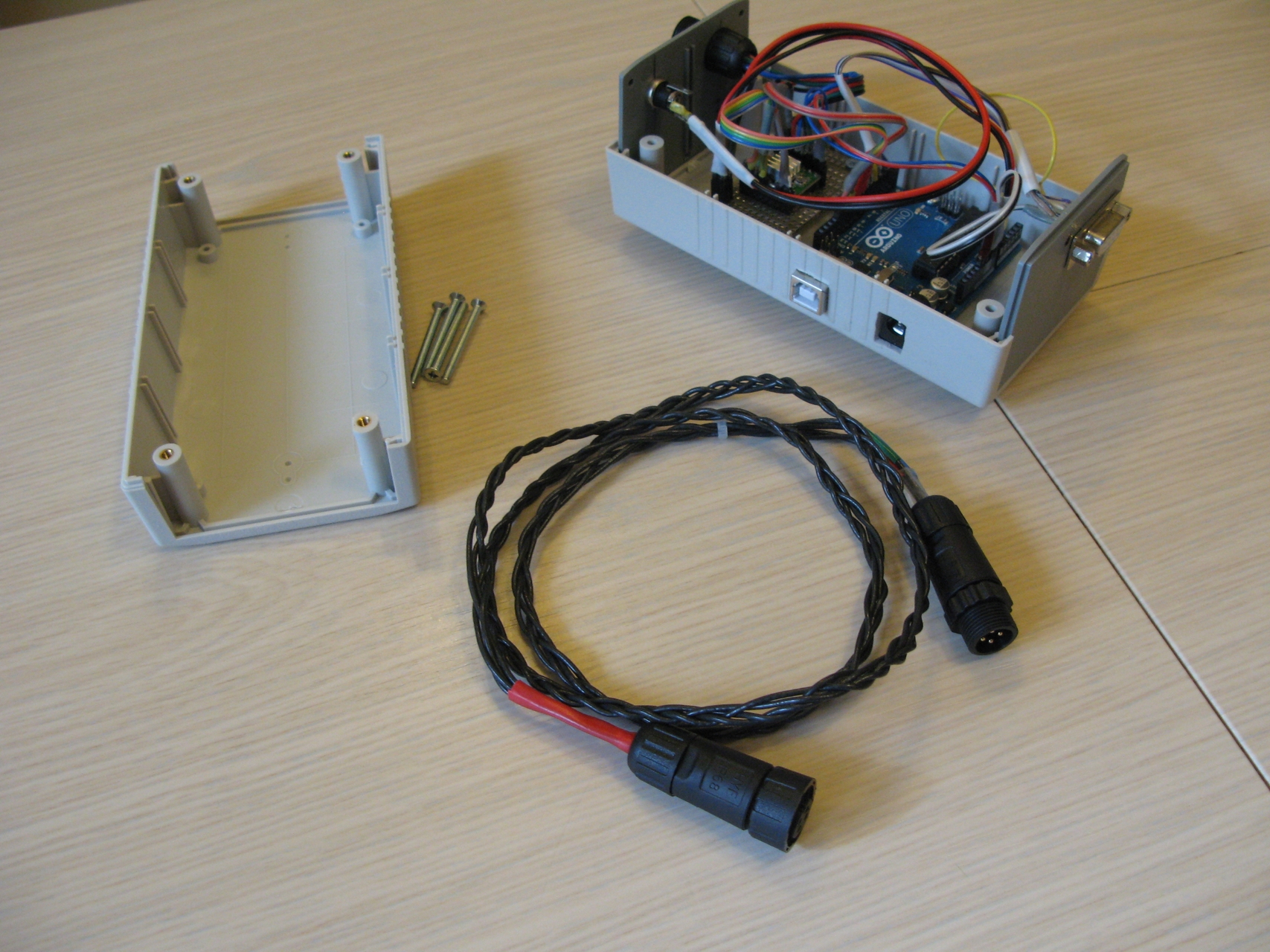
So, the brain of our device is the engine control unit. In order not to clutter and burden the focuser, the Arduino Uno microcontroller board and the A4988 driver, I put them in a separate standard industrial building with. Accordingly, the following connectors are displayed on the case:

As experience has shown, I chose not the most successful, albeit very high-quality case. You can take a similar one, but a couple of centimeters lower, and 1-2 centimeters wider.
I place the control unit under the telescope or on a shelf on a tripod. Accordingly, the cable length BU - the motor should be about 1m. The cable is 4-core, with a cross section sufficient for current up to 2A. You can weave yourself.
Again, you can choose any case, just to be able to place a printed circuit board inside. I recommend first preparing the printed circuit board, and then choosing the case .
A separate word about the circuit board. I really did not want to engage in PCB layout, so I took the finished breadboard for soldering DIP-1M , cut a quarter from it under A4988, and used the rest for the remote control.
That's all for today. Full details on the selected components are available here .
The circuit diagram is given here and in the first part .
In the next part, we get to the microcontroller code and the control panel code for Windows.
Definition of initial device requirements. The choice of hardware
In order not to solve the problem in a very general way, I asked myself certain requirements based on general considerations (budget, simplicity or complexity of component purchase, difficulty in implementation or expected problems in operation). At the same time, the presentation of these considerations will allow you to immediately translate a possible dialogue into a constructive direction, and for those who want to use my experience, they will tell you what details you need to pay attention to. So let's get started.
General requirements
The solution should be:
- simple and not expensive;
- built on available components;
- the device should be reliable enough, since I plan to use it on trips (that is, in a sturdy case, connectors screwed on, etc.);
- the device must be maintainable;
- development should not require me really deep knowledge in electronics and circuitry and go far beyond the school course;
- development should not be delayed, not only for months, but even for weeks;
- I don’t want to do wiring, etching boards, etc. - I want to make the most of ready-made components, preferably in the form of modules.
Functional
The main functions of the device:
- counterclockwise rotation at a given speed (tact button, while pressed - rotate)
- clockwise rotation at a given speed (tact button, while pressed - rotate)
- speed adjustment (potentiometer)
- “release engine” command - remove voltage from the engine (to save battery life and to cool the engine, if necessary)
- In addition, it is useful to insert the function of automatic removal of voltage from the engine if the focuser is not used for a long time (say, more than 10 minutes) - here are possible options;
- It would be nice to have on the remote control a simple indication of the speed of rotation, for example, the brightness of the LED.
Based on the method of application, it is necessary to have at least two options for controlling the focusing device:
- from the control panel when working directly at the telescope (including during visual observations or with rough focusing on the image on the digital camera display) - that is, the button remote control on a short cable is quite fine with me;
- using your own software from a laptop under OS Windows, that means the focuser control unit must be connected to a PC, for example via USB;
- optionally, in the future - from a PC using the ASCOM driver.
When working remotely with a PC, I want to be able to memorize the position of the focuser in the same way and go to the given position. This is due to the fact that when changing the eyepiece, the focal length changes and the focusing procedure must be carried out again. I would like to save the focuser positions for each eyepiece in the form of presets and quickly switch between them when changing the eyepiece. Of course, you will have to refocus the telescope, but this can not be avoided in any case, since at different temperatures the focal length may differ slightly. Based on this, the firmware of the microcontroller should take steps (considering the microstep mode) and transfer the current position to the PC, as well as scroll the focuser to the specified position.
Engine and driver
The motor is unambiguously stepping, since most of the time the focuser is stationary, rotation is required at low revolutions, with accurate focusing, rotation is required to the smallest possible angle, and most of the time rigid position fixation is required - the stepping motor is ideal for solving this problem.
Motor Connection - Bipolar
Bipolar. This is because it is the bipolar connection that gives maximum torque at low revs. If an engine with 6 taps is used, it is necessary to use extreme, medium insulate. It should be borne in mind that the resistance of the windings in this case increases 2 times, respectively, the current drops twice, respectively, the torque decreases.
An extremely important parameter by which you need to choose an engine is the required engine torque . In my case, the maximum torque that I managed to fix was ~ 2 kg / cm at room temperature.
Wanting to have some margin, I set a minimum torque of 3 kg / cm.
How to measure torque without measuring equipment at home.
This is easy enough to do. To do this, you need to attach a lever to the shaft of the focusing device (you can use the focusing wheel itself, catching on its edge) and use a dynamometer to measure the force at which the shaft “breaks down”. To do this, gradually increasing the force, we pull the dynamometer strictly perpendicular to the axis of the lever (naturally in the plane of the lever, perpendicular to the axis of the focuser shaft) and we catch the moment the rotation begins.
Scheme 2
Do not forget to bring the dynamometer readings to the required units and multiply by the lever arm (usually the torque is indicated in N * m or in kg * cm). What if there is no dynamometer? Take steelyard, kitchen scales or do it yourself using a spring and a ruler, for example, like this:
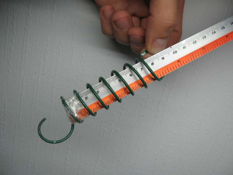
In the latter case, calibration is necessary, which can be done using a bottle of water (1l = 1kg). The accuracy is certainly not high, but for our task is quite sufficient.
It is important to note that the frictional force on the bearings or the worm mechanism of the focuser can greatly depend on the orientation of the latter in space (on the telescope), as well as on the weight attached to the focuser of the equipment (adapters, rotary prism, eyepiece, digital camera, etc.) . Therefore, I recommend hanging a maximum of equipment and taking measurements (2-3 times) in several positions (at least in two when the optical axis of the focuser is oriented vertically and horizontally).
In addition, it must be borne in mind that in cold weather the frictional force can increase markedly, accordingly, more torque will be required.
UPD! Another very important point - usually manufacturers indicate the rated torque. That is, the moment, at rated voltage, rated current and full step ! It will become clear below that in order to achieve the required accuracy, one needs to use the microstep mode, in which the torque drops significantly! Therefore, it is absolutely necessary to choose the engine according to the amount of torque with a margin.
Scheme 2
Do not forget to bring the dynamometer readings to the required units and multiply by the lever arm (usually the torque is indicated in N * m or in kg * cm). What if there is no dynamometer? Take steelyard, kitchen scales or do it yourself using a spring and a ruler, for example, like this:
In the latter case, calibration is necessary, which can be done using a bottle of water (1l = 1kg). The accuracy is certainly not high, but for our task is quite sufficient.
It is important to note that the frictional force on the bearings or the worm mechanism of the focuser can greatly depend on the orientation of the latter in space (on the telescope), as well as on the weight attached to the focuser of the equipment (adapters, rotary prism, eyepiece, digital camera, etc.) . Therefore, I recommend hanging a maximum of equipment and taking measurements (2-3 times) in several positions (at least in two when the optical axis of the focuser is oriented vertically and horizontally).
In addition, it must be borne in mind that in cold weather the frictional force can increase markedly, accordingly, more torque will be required.
UPD! Another very important point - usually manufacturers indicate the rated torque. That is, the moment, at rated voltage, rated current and full step ! It will become clear below that in order to achieve the required accuracy, one needs to use the microstep mode, in which the torque drops significantly! Therefore, it is absolutely necessary to choose the engine according to the amount of torque with a margin.
The next important parameter is positioning accuracy. Since I have already decided that I will use a stepper motor, the question is: what step should the motor have and should I use a driver with microstep support? Most available engines have a step of 1.8 ° per revolution (or 200 steps), but models with a step of 0.9 ° (400 steps per revolution), 7.5 ° and others are also available. This parameter is also individual. In my case, the focus area was about 15 °.
Focus angle measurement
To assess the accuracy of positioning, it is necessary to determine at what angle we rotate the shaft of the focusing device when focusing. To do this, I put a label on the focuser handle - a zero point. Further, using a mask, Bakhtinov focused on the star. I measured the angle a1 - the position of the mark relative to the plummet by the protractor. Then he defocused the image (in either direction) so that the lack of focus was clearly noticeable (the middle beam was substantially shifted away from the center of symmetry of the diffraction pattern). Measured the angle a2 - the second position of the mark relative to the plumb line. The difference in values (a1-a2) modulo multiplied by 2 is the focus area.
Scheme 3
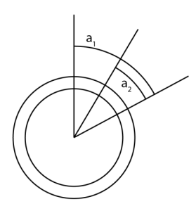
At the same time, accurate focusing (the minimum angle at which the shift of the middle beam from the center becomes noticeable) is less than 2 ° (the selected technique does not allow more accurate measurements, but this is not necessary). Thus, when using the engine in increments of 1.8 °, the entire focus area will be covered in about 10 steps, and precise focusing will be virtually impossible. A step of 0.9 ° is also likely to be insufficient for good focus.
By measuring the angle at which focusing is performed with different eyepieces, I got different values, but of the same order - 10-20 °. So the influence of the eyepiece in this case is probably not fundamental.
Scheme 3
At the same time, accurate focusing (the minimum angle at which the shift of the middle beam from the center becomes noticeable) is less than 2 ° (the selected technique does not allow more accurate measurements, but this is not necessary). Thus, when using the engine in increments of 1.8 °, the entire focus area will be covered in about 10 steps, and precise focusing will be virtually impossible. A step of 0.9 ° is also likely to be insufficient for good focus.
By measuring the angle at which focusing is performed with different eyepieces, I got different values, but of the same order - 10-20 °. So the influence of the eyepiece in this case is probably not fundamental.
As a result, I came to the conclusion that you can use a stepper motor with a pitch of 1.8 ° or 0.9 °, but in any case you need a stepper motor driver with micro-step support. For this reason, I had to abandon the use of popular drivers distributed as Arduino Shield - all of them do not support microsteps. The choice fell on the easily accessible and cheap Polulu A4988 , which really had to be placed on a separate board.
Later, in the next project, I used the DRV8825 of the same manufacturer and I liked it much more.
"To control the A4988, you need at least 6 signals - ENABLE, STEP, DIR and three microstep selection signals MS1, MS2, MS3. Considering the three buttons on the remote control (left, right and “release”) and the speed LED, it turns out that you have to use 10 digital outputs of the microcontroller.
Skipping a step and low accuracy in microstepping mode - myths and reality
You can often hear that the stepper motor in the microstep mode necessarily skips steps, is inaccurately positioned, the torque falls catastrophically, etc., and that they say that they should not be used at all. After spending some time on this issue, I got the impression that this is a common misconception. This is confirmed by both my own experiments and various sources on the network. I am not an expert in this field, I will try to summarize the information collected (theoretical and experimental), leaving the reader to make the final conclusion. So, the most common claims for SD and microstep:
Briefly and very succinctly about SD is described here , here and very well here.
Most often, the problem of skipping steps is not a problem of SD, but the problem of either insufficient power supply, or the problem of "overload". The first problem is solved quite easily by choosing the right power supply and setting the correct position on the A4988 limiter. The second requires careful consideration of all focuser load options. It is also necessary to solve the problem of increasing the required torque for rotation due to an increase in the friction force (on the motor shaft and on the focuser) at low temperatures. It can be solved in different ways. You can take a more powerful engine, or you can use frost-resistant grease.
Therefore, I believe that the SD is practically ideal for this task, and the problem of skipping steps is the problem of choosing the correct SD and operating mode. So that the power of the stepper motor is enough to give sufficient torque in all situations.
- In microstep mode, torque drops very much. Yes, indeed, the popular theoretical models of SD give a significant drop in torque when switching to a microstep. And the smaller the step, the greater the loss. At the same time, in a number of sources (for example, here and here ). I also did not notice that in my experiments the torque fell even 3 times, although I work in the 1/16 and 1/32 microstep modes.
- In microstep mode, the SD must skip steps.
Let's see why a step may be skipped. The main reasons indicated by the manufacturers:- Inadequate nutrition On the A4988 driver there is a regulator (limiter) of the current strength, turn it around and immediately see how insufficient current (and in fact a loss of torque) affects the microstep. By decreasing the current strength, gradually instead of 16 microsteps it is possible to get 8 first and then stable 4. Firstly, the torque in the different phases of the full step is also different;
- Too much load torque . That is, the torque applied to the engine is obviously greater than that given by this engine in certain phases - at this moment we have gaps;
- Speed too high. SD does not have time to pace. For this task is not relevant;
- Braking / acceleration too fast. In this task is not relevant;
- Bad engine. And this also happens.
Briefly and very succinctly about SD is described here , here and very well here.
Most often, the problem of skipping steps is not a problem of SD, but the problem of either insufficient power supply, or the problem of "overload". The first problem is solved quite easily by choosing the right power supply and setting the correct position on the A4988 limiter. The second requires careful consideration of all focuser load options. It is also necessary to solve the problem of increasing the required torque for rotation due to an increase in the friction force (on the motor shaft and on the focuser) at low temperatures. It can be solved in different ways. You can take a more powerful engine, or you can use frost-resistant grease.
Therefore, I believe that the SD is practically ideal for this task, and the problem of skipping steps is the problem of choosing the correct SD and operating mode. So that the power of the stepper motor is enough to give sufficient torque in all situations.
Nutrition
Arduino Uno is powered by a fairly wide voltage range (recommended range of 7-12V) and low current, so when choosing a power source, you actually have to push it away from the engine. The A4988 driver supports voltages from 8 to 35V. Stepper motors are presented in a wide range, with different rated parameters (for different voltage and current). I would like to use a power source for both the control unit and the engine itself. From here we get a limitation: the supply voltage should be in the range of 8-12V. The final choice can be made after the choice of engine is made based on the required power.
In addition, it is worth considering the place of use of the telescope. In my case, this is a loggia (~ 220V), roof of the house (battery), on the road (car, 12V or ~ 220V through an inverter, but sometimes you have to leave the car and then again the battery). Perhaps someone should immediately choose a battery instead of a power supply.
Mechanics
I chose the coaxial placement of the engine: with the help of a coupling, the engine is fixed directly on the shaft of the focusing device. The second fulcrum is an arbitrary rigid mount of the engine to the focuser body. Simple and reliable, although it requires more torque. Such a scheme will simplify the fastening as much as possible (one point), facilitate the removal and installation of the engine if necessary, and, most importantly, avoid the “alignment” of the mechanical part - mounting and fitting gears, pulleys, etc.
Scheme 1
Weight and dimensions
Since the engine is placed on a focusing device on a telescope, weight is important. Too much weight will complicate the balancing, increase the load on the mount and tripod, dimensions - add windage. Therefore, the smaller the engine, the better. This criterion is quite individual, I asked the maximum engine weight of 300 g.
Selection of key components (platform, SD, PSU, housing, etc.)
Engine selection
So, we have already determined that we need a stepper motor with certain
characteristics.
- Step 1.8 ° or 0.9 °;
- Torque from 3 kg / cm;
- Rated voltage 12V;
- Winding current - the smaller the better, a reasonable limitation is not more than 1A;
- The connection is bipolar (respectively 4 taps, if you choose a unipolar motor with 6 taps, do not forget to double the resistance of the windings and recount the current);
- Weight - no more than 0.3 kg;
- Dimensions Keep in mind that a motor that is too large in some mounting positions may interfere with other equipment. This parameter also makes sense to minimize.
Next, launch a browser and look for a suitable engine on the Internet. The average cost in China is 10-20USD, the average cost in the Russian Federation is 1000-1500r. We try to choose an engine with the lowest rated current possible. Theoretically, you can use motors with a current of up to 2A, but a large current will lead to strong heating of the engine (it will have to be turned off every time after focusing) and fast battery consumption. In addition, the A4988 driver has a built-in current limiter, which is good, since it can connect a motor designed for significantly high currents. The bad news is that such an engine will not gain the desired torque.
Examples
Mechanics
To select a coupler, we need to know the bore diameters. To do this, we must measure the diameter of the focuser shaft and look at the diameter of the motor shaft. In my case, it turned out 8 mm and 5 mm, respectively. You will also need to know the torque.
Examples
Mounting the engine to the focuser is a purely individual task. I solved it as follows: I screwed an aluminum corner (specially cut) to the engine, and cut a slot in the focuser's body where this corner entered. This is already enough to exclude cranking, but not enough to exclude backlash. To eliminate the backlash, I took the transformer ring, glued to the inner side a strip of medical waiting and fixed it to the focuser. In the aluminum corner I drilled another hole in place and pulled the clamp with a bolt. The backlash is gone, although of course the whole structure as a whole is not rigid: I got one fulcrum on the focuser + mount on the shaft through a flexible coupling. Accordingly, there is little mobility on the coupling. In practice, this mobility does not interfere, but it can "eat" part of the torque to the deformation of the coupling.
This question is creative and very individual.
Platform for control unit
In fact, there are certainly a lot of options, I chose the Arduino Uno.
Why I opted for Arduino Uno or Oda modern modular electronics
Well and most importantly, Arduino Uno has enough number of inputs and outputs and is completely ready for use - no additional wiring is required, take and program.
Moreover, there are a lot of options for implementation, both Arduino-compatible, so implemented on a different architecture, with their development environments and their communities. On Arduino Uno, of course, the light did not converge. We live in an amazing time when using school knowledge on the basis of modular electronics you can solve a variety of problems, mechanizing and automating various processes - telescopes, aquariums, greenhouses, motion sickness of a child in a cradle or control of high-precision processes. The incomprehensible and absurd concept of a “smart home” is limited by climate, lighting, etc. finally acquires some practical meaning, gives some really new quality, which is very difficult or impossible to achieve "manually". Moreover, at a level accessible to many. And it's just perfect!
- Available;
- Not expensive;
- Free development environment;
- C ++ programming;
- Popular platform, support for lovers around the world;
- RS232 support - when you connect the microcontroller's debug board (USB) to a PC, a COM port appears in the system. Support for working with RS232 from the side of the program executed by the microcontroller is also available, and from the point of view of programming, everything is VERY simple.
Well and most importantly, Arduino Uno has enough number of inputs and outputs and is completely ready for use - no additional wiring is required, take and program.
Moreover, there are a lot of options for implementation, both Arduino-compatible, so implemented on a different architecture, with their development environments and their communities. On Arduino Uno, of course, the light did not converge. We live in an amazing time when using school knowledge on the basis of modular electronics you can solve a variety of problems, mechanizing and automating various processes - telescopes, aquariums, greenhouses, motion sickness of a child in a cradle or control of high-precision processes. The incomprehensible and absurd concept of a “smart home” is limited by climate, lighting, etc. finally acquires some practical meaning, gives some really new quality, which is very difficult or impossible to achieve "manually". Moreover, at a level accessible to many. And it's just perfect!
Power supply selection
A very popular voltage is 12V and it was on it that I stopped. It is suitable for Arduino; there are many stepper motors on the market designed for this voltage; there is a mass of power supplies, batteries, you can connect directly from the car cigarette lighter.
For my device, I settled on a 12V and 25 watt power supply .
A little more details ..
The choice of power supply is carried out according to two main parameters - voltage and power. In my case, U = 12V. Power can be estimated by knowing the maximum current as I * U. Based on 2A on the engine and a voltage of 12V, we get 24 watts.
With a battery, it is similar, but instead of power, it makes sense to look at the capacity and operating current. Current - up to 2A, capacity based on 2-3 hours of operation - say 4-5 A * hours. In practice, it hardly takes more than an hour to focus in total during the night, so a capacity of 2 A * hours should also be enough.
Following the general power condition for the Arduino and the engine, I combined the GND and VIN buses of the Arduino microcontroller board with the GN49 and VMOT buses of the A4988 driver, respectively ( see diagram) At the same time, a second power connector, similar to the Arduino power connector, is displayed on the case. This is done so that in case of replacing the engine with a more powerful one with a different power supply (for example, 24V), it would be possible to separate VIN and VMOT buses without any problems and apply the required voltage to the engine.
Constructive
Since initially when developing the device I set the condition for using standard components, all the components from the specification below are available in stores, and the vast majority can be ordered on the Internet.
The joys of a beginner, or what they don’t write about in datasheets ...
I just want to remind one proverb - “Measure 7 times, order one” :) After assembling I had a bunch of spare parts, but I had to order some for the second time :)
I would like to say a few words about the placement of connectors in the case and buttons on the prototype circuit board. When placing the connectors, take into account that the case will close and place the connectors so that they do not interfere with the assembly. When placing the buttons, keep in mind that the button is put on the cap after assembly, and this cap may be wider than the button itself. Therefore, if you put the buttons on the board too close to each other - the caps will have to be filed :) It’s also worth noting the height of the buttons — they should leave the case enough to put on a cap (the height of the buttons should be taken into account when ordering the remote control case DU).
I would like to say a few words about the placement of connectors in the case and buttons on the prototype circuit board. When placing the connectors, take into account that the case will close and place the connectors so that they do not interfere with the assembly. When placing the buttons, keep in mind that the button is put on the cap after assembly, and this cap may be wider than the button itself. Therefore, if you put the buttons on the board too close to each other - the caps will have to be filed :) It’s also worth noting the height of the buttons — they should leave the case enough to put on a cap (the height of the buttons should be taken into account when ordering the remote control case DU).
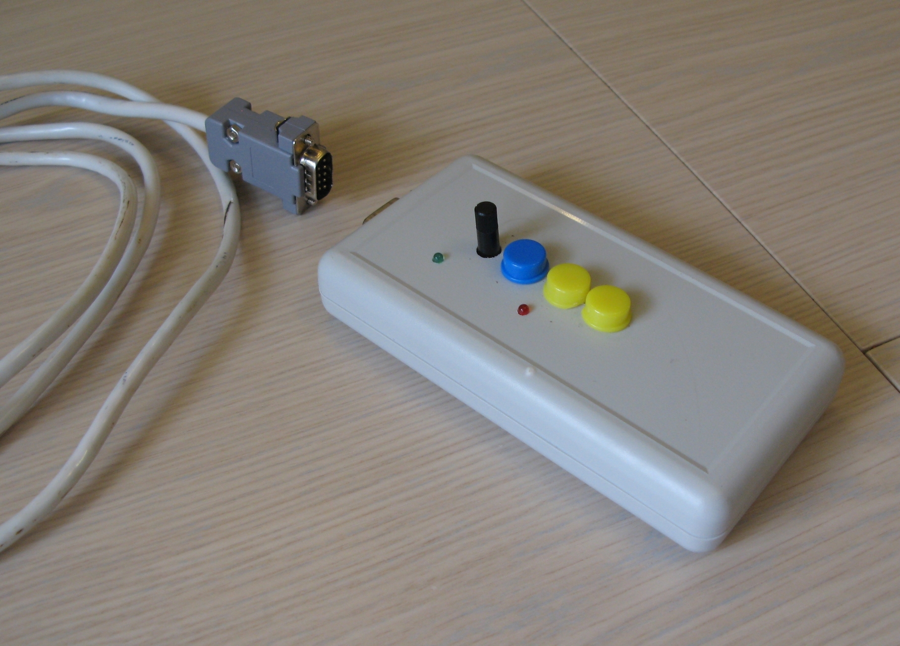
The engine control unit
So, the brain of our device is the engine control unit. In order not to clutter and burden the focuser, the Arduino Uno microcontroller board and the A4988 driver, I put them in a separate standard industrial building with. Accordingly, the following connectors are displayed on the case:
- Power supply (standard Arduino connector and a separate connector for independent engine power supply, if necessary)
- Motor power cable connector
- Microcontroller USB port for PC and remote control
- Remote control connector
As experience has shown, I chose not the most successful, albeit very high-quality case. You can take a similar one, but a couple of centimeters lower, and 1-2 centimeters wider.
I place the control unit under the telescope or on a shelf on a tripod. Accordingly, the cable length BU - the motor should be about 1m. The cable is 4-core, with a cross section sufficient for current up to 2A. You can weave yourself.
Remote control
Again, you can choose any case, just to be able to place a printed circuit board inside. I recommend first preparing the printed circuit board, and then choosing the case .
A separate word about the circuit board. I really did not want to engage in PCB layout, so I took the finished breadboard for soldering DIP-1M , cut a quarter from it under A4988, and used the rest for the remote control.
That's all for today. Full details on the selected components are available here .
The circuit diagram is given here and in the first part .
In the next part, we get to the microcontroller code and the control panel code for Windows.