Hexagon Cards in Unity: Parts 1-3
- Transfer
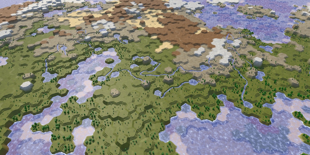
From the translator: this article is the first of a detailed (27 parts) series of tutorials on creating maps from hexagons. This is what should happen at the very end of the tutorials.
Parts 1-3: mesh, colors and height of cells
Parts 4-7: bumps, rivers and roads
Parts 8-11: water, objects of relief and walls of
Parts 12-15: preservation and loading, textures, distances
Parts 16-19: search paths, player squads, animations
Parts 20-23: fog of war, exploration map, procedural generation
Parts 24-27: water cycle, erosion, biomes, cylindrical map
Part 1: Creating a grid of hexagons
Table of contents
- Transform squares into hexagons.
- Triangulate the grid of hexagons.
- We work with cubic coordinates.
- Interact with mesh cells.
- Create an in-game editor.
This tutorial is the beginning of a series of hexagon maps. Hexagonal grids are used in many games, especially strategies, including Age of Wonders 3, Civilization 5 and Endless Legend. We will start with the basics, we will gradually add new features and as a result we will create a complex relief based on hexagons.
This tutorial assumes that you have already studied the Mesh Basics series , which begins with the Procedural Grid . It was created on Unity 5.3.1. The series uses several versions of Unity. The last part is made on Unity 2017.3.0p3.
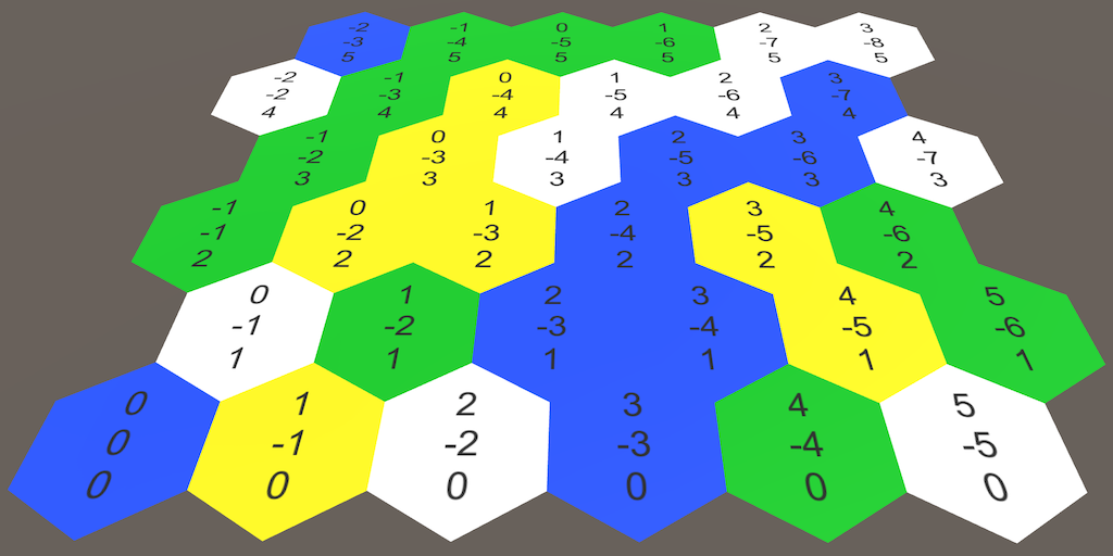
Simple card made of hexagons.
About hexagons
Why do we need hexagons? If we need a grid, then it is logical to use squares. Squares are really just drawing and positioning, but they also have a drawback. Look at the separate grid square, and then at its neighbors.
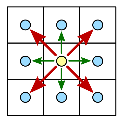
The square and its neighbors.
In total, the square has eight neighbors. Four of them can be reached by going over the edge of the square. These are horizontal and vertical neighbors. The other four can be reached by going through the corner of the square. These are diagonal neighbors.
What is the distance between the centers of neighboring square grid cells? If the edge length is 1, then for horizontal and vertical neighbors the answer is 1. But for diagonal neighbors, the answer is √2.
The difference between the two types of neighbors leads to difficulties. If we use discrete movement, then how to perceive movement along the diagonal? Do you allow it at all? How to make the look more organic? Different games use different approaches with their own advantages and disadvantages. One approach is not to use a square grid at all, but instead use hexagons.
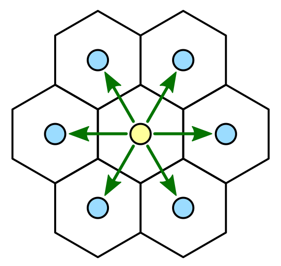
Hexagon and its neighbors.
In contrast to the square, the hexagon has not eight, but six neighbors. All these neighbors are neighbors, there are no corner neighbors. That is, there is only one type of neighbors, which simplifies a lot. Of course, a grid of hexagons is more difficult to build than a square one, but we can handle it.
Before we get to work, we need to determine the size of the hexagons. Let the length of the edge be 10 units. Since the hexagon consists of a circle of six equilateral triangles, the distance from the center to any angle is also equal to 10. This value determines the outer radius of the hexagonal cell.

The outer and inner radius of the hexagon.
There is also an internal radius, which is the distance from the center to each of the edges. This parameter is important because the distance between the centers of the neighbors is equal to this value multiplied by two. Inner radius is
using UnityEngine;
publicstaticclassHexMetrics {
	publicconstfloat outerRadius = 10f;
	publicconstfloat innerRadius = outerRadius * 0.866025404f;
}
How to display the value of the inner radius?
Возьмём один из шести треугольников шестиугольника. Внутренний радиус равен высоте этого треугольника. Эту высоту можно получить, разделив треугольник на два правильных треугольника, после чего воспользоваться теоремой Пифагора.
Поэтому для длины ребра внутренний радиус равен
  .
.
Поэтому для длины ребра
If we are already engaged in this, then let's define the positions of the six corners relative to the center of the cell. It should be noted that there are two ways to orient a hexagon: upwards with a sharp or flat side. We will put up the corner. Let's start from this angle and add the rest clockwise. Place them on the XZ plane so that the hexagons are on the ground.

Possible orientations.
publicstatic Vector3[] corners = {
		new Vector3(0f, 0f, outerRadius),
		new Vector3(innerRadius, 0f, 0.5f * outerRadius),
		new Vector3(innerRadius, 0f, -0.5f * outerRadius),
		new Vector3(0f, 0f, -outerRadius),
		new Vector3(-innerRadius, 0f, -0.5f * outerRadius),
		new Vector3(-innerRadius, 0f, 0.5f * outerRadius)
	};
unitypackage
Grid construction
To build a grid of hexagons, we need grid cells. For this purpose we will create a component
HexCell. For now, let's leave it empty, because we are not using any of these cells yet.using UnityEngine;
publicclassHexCell : MonoBehaviour {
}To start with the simplest, create a default plane object, add a cell component to it and turn it all into a prefab.
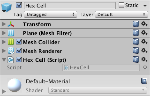
Using the plane as a hex prefab cell.
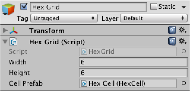
Now let's do the grid. Create a simple component with common variable widths, heights, and cell prefabs. Then we add a game object with this component to the scene.
using UnityEngine;
publicclassHexGrid : MonoBehaviour {
	publicint width = 6;
	publicint height = 6;
	public HexCell cellPrefab;
}
Mesh object made of hexagons.
Let's start by creating a regular grid of squares, because we already know how to do it. Save the cells in the array to be able to access them.
Since the planes by default have a size of 10 by 10 units, we will shift each cell by this value.
	HexCell[] cells;
	voidAwake () {
		cells = new HexCell[height * width];
		for (int z = 0, i = 0; z < height; z++) {
			for (int x = 0; x < width; x++) {
				CreateCell(x, z, i++);
			}
		}
	}
	voidCreateCell (int x, int z, int i) {
		Vector3 position;
		position.x = x * 10f;
		position.y = 0f;
		position.z = z * 10f;
		HexCell cell = cells[i] = Instantiate<HexCell>(cellPrefab);
		cell.transform.SetParent(transform, false);
		cell.transform.localPosition = position;
	}
Square grid of planes.
So we got a beautiful solid grid of square cells. But which cell is where? Of course, it is easy to check, but with hexagons there will be difficulties. It would be convenient if we could simultaneously see the coordinates of all the cells.
Coordinate display
Add a canvas to the scene by selecting GameObject / UI / Canvas and make it a child of our grid object. Since this canvas is only for information, we will remove its raycaster component. You can also delete the event system object that was automatically added to the scene, because until we need it.
Select to Render Mode value of the World Space and turn it by 90 degrees on the X axis to canvas superimposed on the grid. Set the pivot and position to zero. Give it a slight vertical offset so that its contents are at the top. Width and height are not important to us, because we have the content on our own. We can assign a value of 0 to get rid of a large rectangle in the scene window.
As a final touch, let's increase Dynamic Pixels Per Unit to 10. So we guarantee that text objects will use sufficient texture resolution.

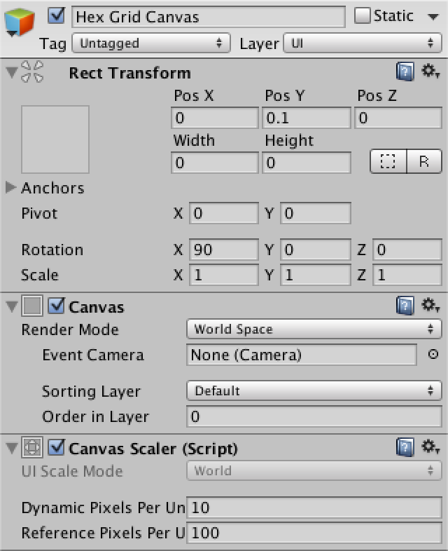
Canvas for coordinates of a grid of hexagons.
To display the coordinates, create a Text object ( GameObject / UI / Text ) and turn it into a prefab. Center its anchors and pivot, set the size to 5 to 15. The text must also be horizontally and vertically aligned in the center. Let's set the font size to 4. Finally, we do not want to use the default text and will not use Rich Text . Also, it doesn't matter to us whether Raycast Target is enabled , because for our canvas it will not be needed anyway.
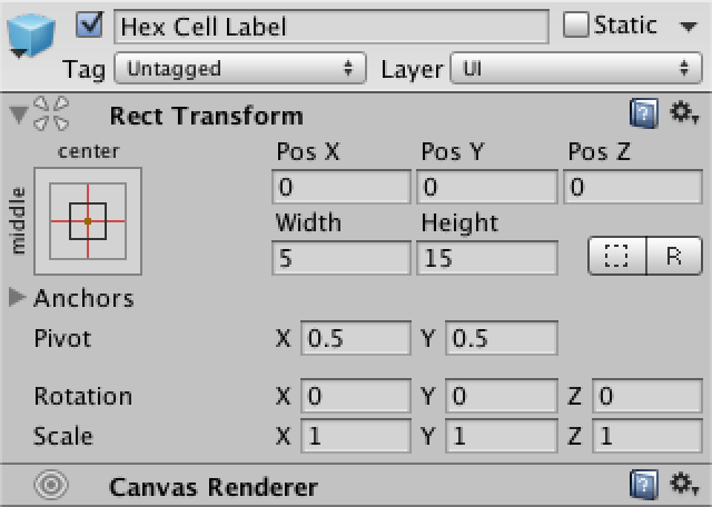

Prefab label cells.
Now we need to tell the grid about the canvas and the prefab. Add to the beginning of its script
using UnityEngine.UI;to conveniently access the type UnityEngine.UI.Text. For the prefab label, a shared variable is needed, and the canvas can be found as a challenge GetComponentInChildren.public Text cellLabelPrefab;
Canvas gridCanvas;
voidAwake () {
gridCanvas = GetComponentInChildren<Canvas>();
…
}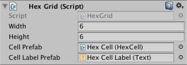
Connection prefab tags.
After connecting the label prefab, we can create its instances and display the coordinates of the cell. Insert a newline character between X and Z so that they are on separate lines.
voidCreateCell (int x, int z, int i) {
		…
		Text label = Instantiate<Text>(cellLabelPrefab);
		label.rectTransform.SetParent(gridCanvas.transform, false);
		label.rectTransform.anchoredPosition =
			new Vector2(position.x, position.z);
		label.text = x.ToString() + "\n" + z.ToString();
	}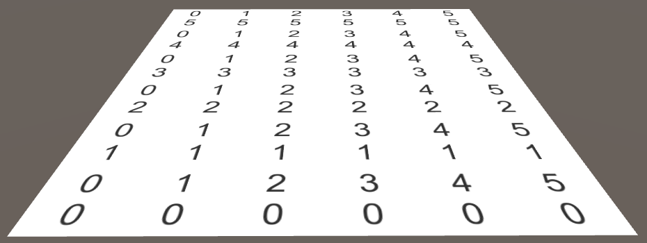
Coordinate display.
Hexagon positions
Now that we can visually recognize each cell, let's get down to moving them. We know that the distance between adjacent hexagonal cells in the X direction is equal to twice the inner radius. We will take advantage of this. In addition, the distance to the next row of cells should be 1.5 times greater than the outer radius.
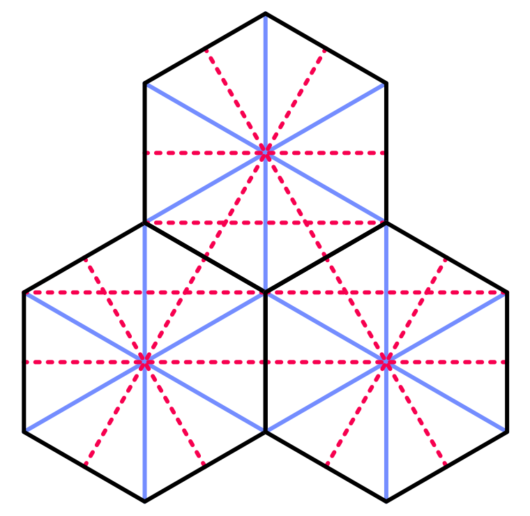
Geometry of adjacent hexagons.
		position.x = x * (HexMetrics.innerRadius * 2f);
		position.y = 0f;
		position.z = z * (HexMetrics.outerRadius * 1.5f);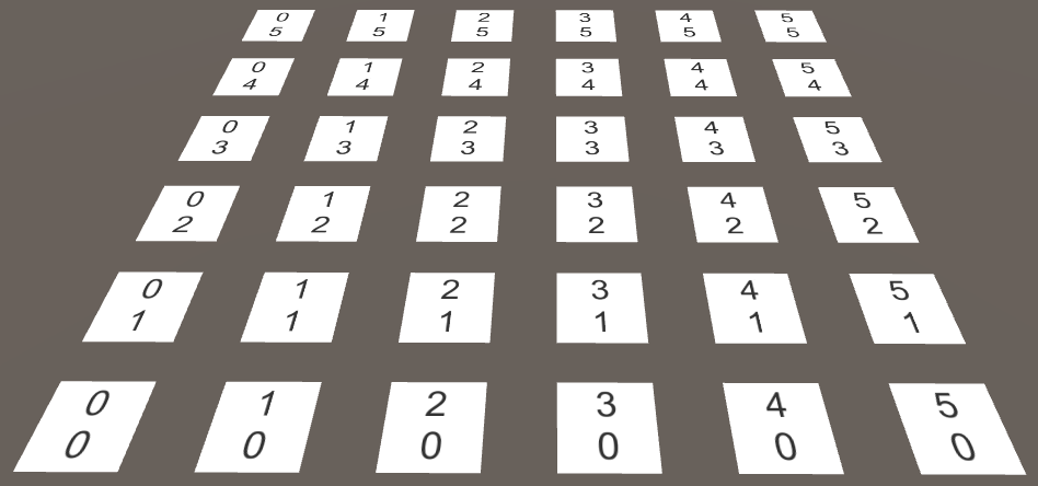
Apply the distance between the hexagons without offsets.
Of course, the ordinal rows of hexagons are not located exactly one above the other. Each line is shifted along the X axis by the value of the inner radius. This value can be obtained by adding half of Z to X, and then multiplied by twice the inner radius.
position.x = (x + z * 0.5f) * (HexMetrics.innerRadius * 2f);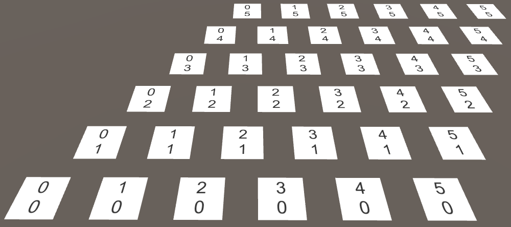
Proper placement of the hexagons creates a diamond-shaped grid.
Although we placed the cells in the correct positions of the hexagons in this way, our grid now fills a rhombus, not a rectangle. It is much more convenient for us to work with rectangular grids, so let's force the cells to return to the system. This can be done by reversing the offset part. In every other row, all cells must move back one extra step. To do this, we need to subtract the result of the integer division of Z by 2 before the multiplication.
position.x = (x + z * 0.5f - z / 2) * (HexMetrics.innerRadius * 2f);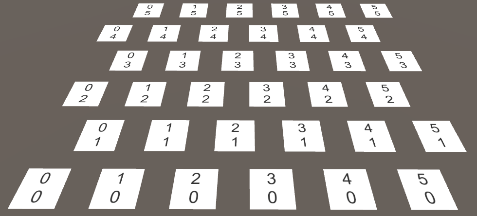
The location of the hexagons in a rectangular area.
unitypackage
Hexagons Rendering
Having correctly placed the cells, we can proceed to the display of real hexagons. First we need to get rid of the planes, so remove all components from the cell prefab except for
HexCell.
There are no more planes.
As in the Mesh Basics tutorials , we use one mesh for rendering the entire grid. However, this time we will not pre-set the number of necessary vertices and triangles. Instead, we will use the lists.
Create a new component
HexMeshthat will deal with our mesh. It will require a mesh filter and renderer, it has a mesh and lists for vertices and triangles.using UnityEngine;
using System.Collections.Generic;
[RequireComponent(typeof(MeshFilter), typeof(MeshRenderer))]
publicclassHexMesh : MonoBehaviour {
Mesh hexMesh;
List<Vector3> vertices;
List<int> triangles;
voidAwake () {
GetComponent<MeshFilter>().mesh = hexMesh = new Mesh();
hexMesh.name = "Hex Mesh";
vertices = new List<Vector3>();
triangles = new List<int>();
}
}Create a new child for our mesh with this component. He will automatically receive a mesh renderer, but no material will be assigned to him. Therefore, add the default material to it.
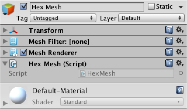
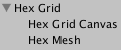
Hex mesh object.
Now he
HexGridcan get his mesh of hexagons in the same way he found the canvas. HexMesh hexMesh;
voidAwake () {
gridCanvas = GetComponentInChildren<Canvas>();
hexMesh = GetComponentInChildren<HexMesh>();
…
}After Awake the mesh, it must order the mesh to triangulate its cells. We need to make sure that this happens after the Awake hex mesh component. Since it
Startis called later, we insert the appropriate code there.voidStart () {
hexMesh.Triangulate(cells);
}This method
HexMesh.Triangulatecan be called at any time, even if the cells have already been triangulated earlier. Therefore, we should start by clearing old data. When traversing a loop through all cells, we triangulate them separately. After completing this operation, let's assign the generated vertices and triangles to the mesh, and finish by recalculating the normals of the mesh.publicvoidTriangulate (HexCell[] cells) {
hexMesh.Clear();
vertices.Clear();
triangles.Clear();
for (int i = 0; i < cells.Length; i++) {
Triangulate(cells[i]);
}
hexMesh.vertices = vertices.ToArray();
hexMesh.triangles = triangles.ToArray();
hexMesh.RecalculateNormals();
}
voidTriangulate (HexCell cell) {
}Since hexagons are made up of triangles, let's create a convenient method for adding a triangle based on the positions of the three vertices. It will simply add vertices in order. He also adds the indices of these vertices to form a triangle. The index of the first vertex is equal to the length of the list of vertices before new vertices are added to it. Keep this in mind when adding vertices.
voidAddTriangle (Vector3 v1, Vector3 v2, Vector3 v3) {
		int vertexIndex = vertices.Count;
		vertices.Add(v1);
		vertices.Add(v2);
		vertices.Add(v3);
		triangles.Add(vertexIndex);
		triangles.Add(vertexIndex + 1);
		triangles.Add(vertexIndex + 2);
	}
Now we can triangulate our cells. Let's start with the first triangle. Its first vertex is in the center of the hexagon. The two other vertices are the first and second angles relative to the center.
voidTriangulate (HexCell cell) {
		Vector3 center = cell.transform.localPosition;
		AddTriangle(
			center,
			center + HexMetrics.corners[0],
			center + HexMetrics.corners[1]
		);
	}
The first triangle of each cell.
It worked, so let's loop around all six triangles in the loop.
		Vector3 center = cell.transform.localPosition;
		for (int i = 0; i < 6; i++) {
			AddTriangle(
				center,
				center + HexMetrics.corners[i],
				center + HexMetrics.corners[i + 1]
			);
		}
Is it possible to make vertices shared?
Да, можно. На самом деле, мы можем сделать ещё лучше и использовать для рендеринга вместо шести треугольников всего четыре. Но отказавшись от этого, мы упростим свою работу, и это будет правильно, поэтому что в следующих туториалах всё становится сложнее. Оптимизация вершин и треугольников на этом этапе помешает нам в будущем.
Unfortunately, this process will lead to
IndexOutOfRangeException. This is because the last triangle is trying to get the seventh corner, which does not exist. Of course, he must go back and use as the last vertex of the first corner. Or we can duplicate the first corner in HexMetrics.corners, so as not to go beyond the boundaries.publicstatic Vector3[] corners = {
new Vector3(0f, 0f, outerRadius),
new Vector3(innerRadius, 0f, 0.5f * outerRadius),
new Vector3(innerRadius, 0f, -0.5f * outerRadius),
new Vector3(0f, 0f, -outerRadius),
new Vector3(-innerRadius, 0f, -0.5f * outerRadius),
new Vector3(-innerRadius, 0f, 0.5f * outerRadius),
new Vector3(0f, 0f, outerRadius)
};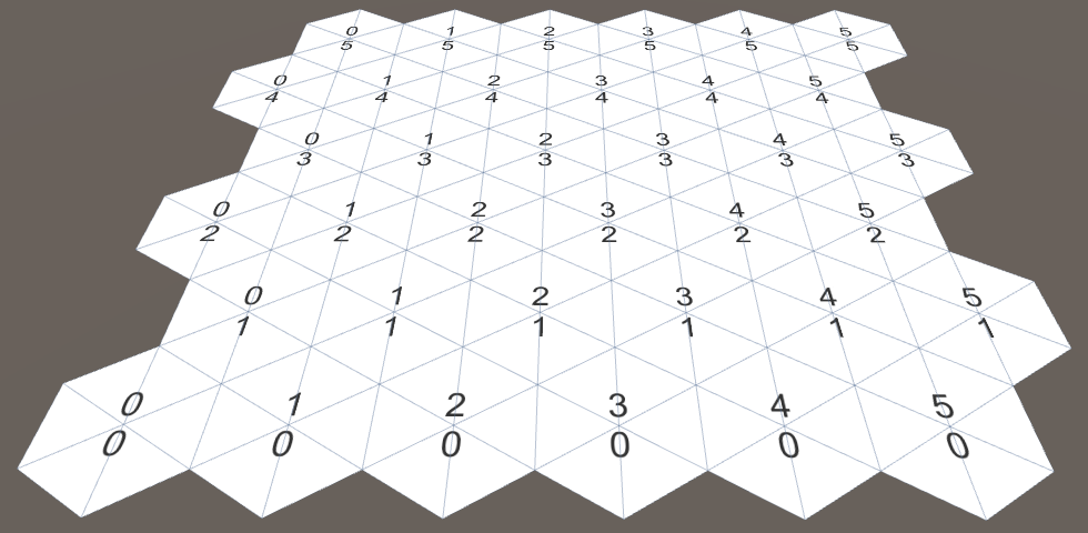
Hexagons completely.
unitypackage
Hexagonal coordinates
Let's look again at the coordinates of the cells, now in the context of a grid of hexagons. The Z coordinate looks normal, and the X coordinate zigzags. This is a side effect of offsetting lines to cover a rectangular area.
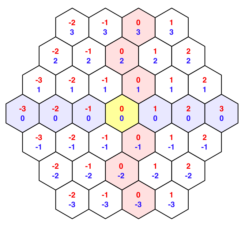
Offset coordinates with highlighted zero lines.
When working with hexagons, it is not easy to handle such offset coordinates. Let's add a struct
HexCoordinatesthat can be used to convert to another coordinate system. Let's make it serializable so that Unity can store it and it experienced recompilation in Play mode. We will also make these coordinates immutable, using the public readonly properties.using UnityEngine;
[System.Serializable]
publicstruct HexCoordinates {
publicint X { get; privateset; }
publicint Z { get; privateset; }
publicHexCoordinates (int x, int z) {
X = x;
Z = z;
}
}Add a static method to create a set of coordinates from the usual offset coordinates. For now we’ll just copy these coordinates.
publicstatic HexCoordinates FromOffsetCoordinates (int x, int z) {
		returnnew HexCoordinates(x, z);
	}
}
Add also convenient string conversion methods. The
ToStringdefault method returns the name of the type struct, which is not very useful to us. Redefine it so that it returns the coordinates on one line. We will also add a method for outputting coordinates to individual lines, because we already use such a scheme.publicoverridestringToString () {
return"(" + X.ToString() + ", " + Z.ToString() + ")";
}
publicstringToStringOnSeparateLines () {
return X.ToString() + "\n" + Z.ToString();
}Now we can transfer a lot of coordinates to our component
HexCell.publicclassHexCell : MonoBehaviour {
public HexCoordinates coordinates;
}Change
HexGrid.CreateCellso that he could use the new coordinates. HexCell cell = cells[i] = Instantiate<HexCell>(cellPrefab);
cell.transform.SetParent(transform, false);
cell.transform.localPosition = position;
cell.coordinates = HexCoordinates.FromOffsetCoordinates(x, z);
Text label = Instantiate<Text>(cellLabelPrefab);
label.rectTransform.SetParent(gridCanvas.transform, false);
label.rectTransform.anchoredPosition =
new Vector2(position.x, position.z);
label.text = cell.coordinates.ToStringOnSeparateLines();Now let's redo these X coordinates so that they are aligned along a straight axis. This can be done by canceling the horizontal shift. The resulting result is usually called the axial coordinates.
publicstatic HexCoordinates FromOffsetCoordinates (int x, int z) {
		returnnew HexCoordinates(x - z / 2, z);
	}
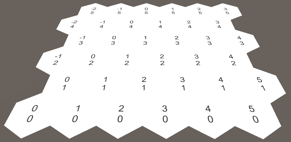
Axial coordinates.
This two-dimensional coordinate system allows us to consistently describe the movement of an offset in four directions. However, the two remaining directions still require special attention. This makes us realize that there is a third dimension. Indeed, if we horizontally turned over the dimension X, we would get the missing dimension Y.

The dimension Y appears.
Since these dimensions X and Y are mirror copies of each other, the addition of their coordinates always gives the same result if Z remains constant. In fact, if we add up all three coordinates, then we will always get zero. If you increase one coordinate, you will have to reduce the other. Indeed, it gives us six possible directions of movement. Such coordinates are usually called cubic, because they are three-dimensional, and the topology resembles a cube.
Since the sum of all coordinates is zero, we can always get any of the coordinates from the other two. Since we already store the X and Z coordinates, we do not need to store the Y coordinate.
We can add a property that calculates it if necessary and use it in string methods.
publicint Y {
		get {
			return -X - Z;
		}
	}
	publicoverridestringToString () {
		return"(" +
			X.ToString() + ", " + Y.ToString() + ", " + Z.ToString() + ")";
	}
	publicstringToStringOnSeparateLines () {
		return X.ToString() + "\n" + Y.ToString() + "\n" + Z.ToString();
	}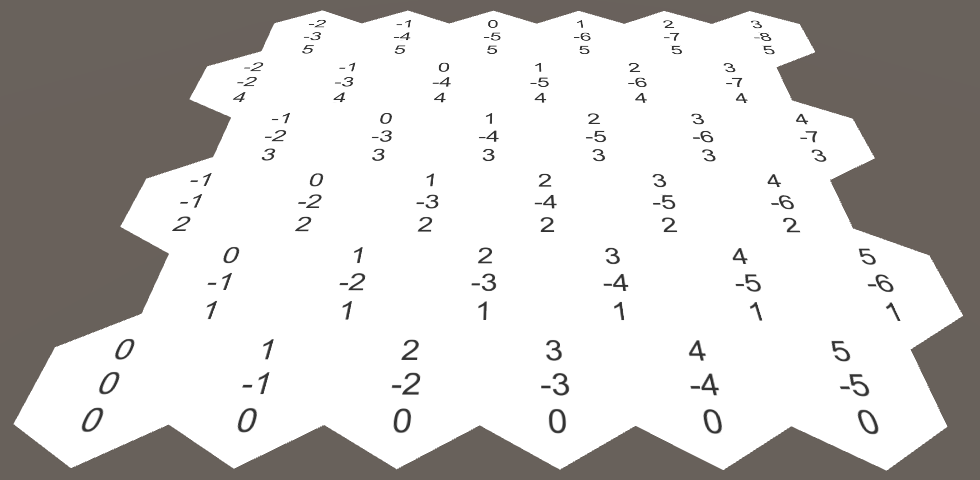
Cubic coordinates.
Coordinates in the inspector
In Play mode, select one of the grid cells. It turns out that the inspector does not display its coordinates, only the prefix label is shown
HexCell.coordinates.
The inspector does not display coordinates.
Although this is not a big problem, it would be great to display the coordinates. Unity does not show coordinates because they are not marked as serializable fields. To display them, you must explicitly specify the serializable fields for X and Z.
	[SerializeField]
	privateint x, z;
	publicint X {
		get {
			return x;
		}
	}
	publicint Z {
		get {
			return z;
		}
	}
	publicHexCoordinates (int x, int z) {
		this.x = x;
		this.z = z;
	}
The X and Z coordinates are now displayed, but you can change them. We do not need it, because the coordinates must be fixed. It is also not very good that they are displayed under each other.
We can do better: define your own property drawer for the type
HexCoordinates. Create a script HexCoordinatesDrawerand paste it into the Editor folder , because this is an editor-only script. The class must extend
UnityEditor.PropertyDrawerand it needs an attribute UnityEditor.CustomPropertyDrawerto associate it with the appropriate type.using UnityEngine;
using UnityEditor;
[CustomPropertyDrawer(typeof(HexCoordinates))]
publicclassHexCoordinatesDrawer : PropertyDrawer {
}Property drawers display their contents using the method
OnGUI. This method allowed us to draw inside the screen rectangle the serializable property data and the label of the field to which they belong.publicoverridevoidOnGUI (
Rect position, SerializedProperty property, GUIContent label
) {
}Extract the values of x and z from the property, and then use them to create a new set of coordinates. Then we will draw a GUI label in the selected position using our method
HexCoordinates.ToString.publicoverridevoidOnGUI (
Rect position, SerializedProperty property, GUIContent label
) {
HexCoordinates coordinates = new HexCoordinates(
property.FindPropertyRelative("x").intValue,
property.FindPropertyRelative("z").intValue
);
GUI.Label(position, coordinates.ToString());
}
Coordinates without prefix label.
So we will display the coordinates, but now we miss the field name. These names are usually drawn using the method
EditorGUI.PrefixLabel. As a bonus, it returns an aligned rectangle that corresponds to the space to the right of this label. position = EditorGUI.PrefixLabel(position, label);
GUI.Label(position, coordinates.ToString());
Coordinates with label.
unitypackage
Touch the cells
The grid of hexagons is not very interesting if we can not interact with it. The simplest interaction is to touch the cell, so let's add support for it. For now, we just paste this code directly into
HexGrid. When he starts working, we will move it to another place. To touch a cell, you can emit rays into the scene from the position of the mouse cursor. We can use the same approach as in the Mesh Deformation tutorial .
voidUpdate () {
		if (Input.GetMouseButton(0)) {
			HandleInput();
		}
	}
	voidHandleInput () {
		Ray inputRay = Camera.main.ScreenPointToRay(Input.mousePosition);
		RaycastHit hit;
		if (Physics.Raycast(inputRay, out hit)) {
			TouchCell(hit.point);
		}
	}
	voidTouchCell (Vector3 position) {
		position = transform.InverseTransformPoint(position);
		Debug.Log("touched at " + position);
	}
While the code does nothing. We need to add a collider to the grid so that the beam can collide with something. Therefore, we will give the
HexMeshmesh of the collider. MeshCollider meshCollider;
voidAwake () {
GetComponent<MeshFilter>().mesh = hexMesh = new Mesh();
meshCollider = gameObject.AddComponent<MeshCollider>();
…
}After the triangulation is completed, assign the mesh to the collider.
publicvoidTriangulate (HexCell[] cells) {
		…
		meshCollider.sharedMesh = hexMesh;
	}
Can't we just use box collider?
Можем, но он не будет точно соответствовать контуру нашей сетки. Да и наша сетка недолго будет оставаться плоской, но это уже тема для будущих туториалов.
Now we can touch the grid! But which cell are we touching? To find out, we need to convert the touch position to the coordinates of the hexagons. This is a job for
HexCoordinates, therefore, we declare that it has a static method FromPosition.publicvoidTouchCell (Vector3 position) {
position = transform.InverseTransformPoint(position);
HexCoordinates coordinates = HexCoordinates.FromPosition(position);
Debug.Log("touched at " + coordinates.ToString());
}How will this method determine which coordinate belongs to the position? We can start by dividing x by the horizontal width of the hexagon. And since the Y coordinate is a mirror image of the X coordinate, a negative value of x gives us y.
publicstatic HexCoordinates FromPosition (Vector3 position) {
		float x = position.x / (HexMetrics.innerRadius * 2f);
		float y = -x;
	}
Of course, this would give us the correct coordinates if Z were equal to zero. We must again perform a shift as we move along Z. Every two lines we must shift to the left by the whole unit.
float offset = position.z / (HexMetrics.outerRadius * 3f);
		x -= offset;
		y -= offset;
As a result, our x and y values are integers in the center of each cell. Therefore, rounding them up to integers, we must get the coordinates. We also calculate Z and thus get the final coordinates.
int iX = Mathf.RoundToInt(x);
		int iY = Mathf.RoundToInt(y);
		int iZ = Mathf.RoundToInt(-x -y);
		returnnew HexCoordinates(iX, iZ);
The results look promising, but are these coordinates correct? With a careful study, you can find that sometimes we get coordinates, the sum of which is not equal to zero! Let's turn on the notification to make sure this really happens.
if (iX + iY + iZ != 0) {
			Debug.LogWarning("rounding error!");
		}
		returnnew HexCoordinates(iX, iZ);
We actually receive notifications. How do we fix this error? It only appears next to the edges between the hexagons. That is, the problem is caused by the rounding of coordinates. Which coordinate is rounded in the wrong direction? The further we move away from the center of the cell, the more rounding we get. Therefore, it is logical to assume that the coordinate that is rounded the most is incorrect.
Then the solution is to drop the coordinate with the largest delta of rounding and recreate it from the values of the other two. But since we only need X and Z, we can not bother recreating Y.
if (iX + iY + iZ != 0) {
			float dX = Mathf.Abs(x - iX);
			float dY = Mathf.Abs(y - iY);
			float dZ = Mathf.Abs(-x -y - iZ);
			if (dX > dY && dX > dZ) {
				iX = -iY - iZ;
			}
			elseif (dZ > dY) {
				iZ = -iX - iY;
			}
		}
Coloring hexagons
Now that we can touch the right cell, it's time for real interaction. Let's change the color of each cell we get into. Add
HexGridcustom cell colors to the default and the affected cell.public Color defaultColor = Color.white;
public Color touchedColor = Color.magenta;
Select the color of the cells.
Add to the
HexCellgeneral field of color.publicclassHexCell : MonoBehaviour {
public HexCoordinates coordinates;
public Color color;
}Assign it
HexGrid.CreateCellto the default color.voidCreateCell (int x, int z, int i) {
…
cell.coordinates = HexCoordinates.FromOffsetCoordinates(x, z);
cell.color = defaultColor;
…
}We also need to add to
HexMeshthe color information. List<Color> colors;
voidAwake () {
…
vertices = new List<Vector3>();
colors = new List<Color>();
…
}
publicvoidTriangulate (HexCell[] cells) {
hexMesh.Clear();
vertices.Clear();
colors.Clear();
…
hexMesh.vertices = vertices.ToArray();
hexMesh.colors = colors.ToArray();
…
}Now, with triangulation, we must add color data to each triangle. For this purpose we will create a separate method.
voidTriangulate (HexCell cell) {
		Vector3 center = cell.transform.localPosition;
		for (int i = 0; i < 6; i++) {
			AddTriangle(
				center,
				center + HexMetrics.corners[i],
				center + HexMetrics.corners[i + 1]
			);
			AddTriangleColor(cell.color);
		}
	}
	voidAddTriangleColor (Color color) {
		colors.Add(color);
		colors.Add(color);
		colors.Add(color);
	}
Let's go back to
HexGrid.TouchCell. First, we transform the coordinates of the cell into the corresponding array index. For a square grid, this would simply be X plus Z multiplied by the width, but in our case we will have to add an offset to half Z. Then we take a cell, change its color and again triangulate the mesh.Do we really need to re-triangulate the whole mesh?
Мы можем поступить умнее, но сейчас не время для таких оптимизаций. В будущих туториалах меш станет гораздо сложнее. Любые допущения и упрощения, которые мы сделаем сейчас, могут в дальнейшем оказаться неверными. Такой способ грубой силы всегда хорошо работает.
publicvoidTouchCell (Vector3 position) {
		position = transform.InverseTransformPoint(position);
		HexCoordinates coordinates = HexCoordinates.FromPosition(position);
		int index = coordinates.X + coordinates.Z * width + coordinates.Z / 2;
		HexCell cell = cells[index];
		cell.color = touchedColor;
		hexMesh.Triangulate(cells);
	}
Although we can now color the cells, visual changes are not yet visible. This happened because the shader does not use vertex colors by default. We have to write our own. Create a new default shader ( Assets / Create / Shader / Default Surface Shader ). It needs to make only two changes. First, add colors to its input struct data. Second, multiply Albedo by this color. We are only interested in RGB channels, because the material is opaque.
Shader "Custom/VertexColors" {
	Properties {
		_Color ("Color", Color) = (1,1,1,1)
		_MainTex ("Albedo (RGB)", 2D) = "white" {}
		_Glossiness ("Smoothness", Range(0,1)) = 0.5
		_Metallic ("Metallic", Range(0,1)) = 0.0
	}
	SubShader {
		Tags { "RenderType"="Opaque" }
		LOD 200
		CGPROGRAM
		#pragma surface surf Standard fullforwardshadows
		#pragma target 3.0
		sampler2D _MainTex;
		struct Input {
			float2 uv_MainTex;
			float4 color : COLOR;
		};
		half _Glossiness;
		half _Metallic;
		fixed4 _Color;
		void surf (InputIN, inout SurfaceOutputStandard o) {
			fixed4 c = tex2D(_MainTex, IN.uv_MainTex) * _Color;
			o.Albedo = c.rgb * IN.color;
			o.Metallic = _Metallic;
			o.Smoothness = _Glossiness;
			o.Alpha = c.a;
		}
		ENDCG
	}
	FallBack "Diffuse"
}
Create a new material using this shader, and then make the mesh mesh use this material. Due to this, the colors of the cells will appear.
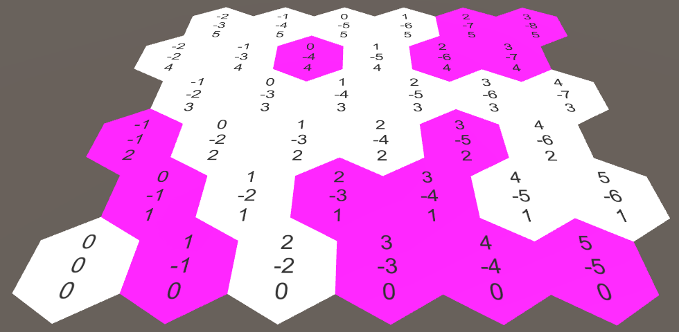
Colored cells.
I have strange shadow artifacts!
В некоторых версиях Unity создаваемые пользователем шейдеры могут вызывать проблемы с тенями. Если у вас возникают некрасивый дизеринг или полосы на тенях, то это значит, что присутствует Z-конфликт. Для решения этой проблемы достаточно изменить отклонение тени от источника направленного освещения.
unitypackage
Map editor
Now that we know how to change colors, let's create a simple in-game editor. This functionality does not apply to features
HexGrid, so we will turn it TouchCellinto a general method with an additional color parameter. Also remove the field touchedColor.publicvoidColorCell (Vector3 position, Color color) {
position = transform.InverseTransformPoint(position);
HexCoordinates coordinates = HexCoordinates.FromPosition(position);
int index = coordinates.X + coordinates.Z * width + coordinates.Z / 2;
HexCell cell = cells[index];
cell.color = color;
hexMesh.Triangulate(cells);
}Create a component
HexMapEditorand move the methods Updateand into it HandleInput. Add a common field to it to reference the hexagonal grid, the array of colors, and the private field to track the active color. Finally, we add a general method for choosing a color and force it to initially select the first color.using UnityEngine;
publicclassHexMapEditor : MonoBehaviour {
public Color[] colors;
public HexGrid hexGrid;
private Color activeColor;
voidAwake () {
SelectColor(0);
}
voidUpdate () {
if (Input.GetMouseButton(0)) {
HandleInput();
}
}
voidHandleInput () {
Ray inputRay = Camera.main.ScreenPointToRay(Input.mousePosition);
RaycastHit hit;
if (Physics.Raycast(inputRay, out hit)) {
hexGrid.ColorCell(hit.point, activeColor);
}
}
publicvoidSelectColor (int index) {
activeColor = colors[index];
}
}Add another canvas, this time saving the default settings. Add a component to it
HexMapEditor, set several colors and connect to the grid of hexagons. This time we need the event system object, and it was automatically created again.
Four-color hexagon map editor.
Add a panel to the canvas for storing color selectors ( GameObject / UI / Panel ). Add to it the toggle group ( Components / UI / Toggle Group ). Make the panel small and place it in the corner of the screen.

Color Bar with toggle group.
Now fill the panel with switches for each color ( GameObject / UI / Toggle ). While we will not bother creating a complex UI, a simple manual configuration is sufficient.


One switch for each color.
Turn on the first switch. Also make all the switches part of the toggle group, so that you can only select one of them at a time. Finally, connect them to the method of
SelectColorour editor. This can be done with the "+" UI event of On Value Changed . Select the map editor object, then select the desired method from the drop-down list.
The first switch.
This event passes a boolean argument that determines whether the switch is turned on each time it is changed. But we do not care. Instead, we have to manually pass an integer argument corresponding to the color index we want to use. Therefore, leave the value 0 for the first switch, set the value to 1 for the second, and so on.
When is the trigger event method called?
Метод вызывается при каждом изменении состояния переключателя. Если этот метод имеет булев параметр, то он сообщает нам, включён ли переключатель.
Так как переключатели являются частями группы, выбор одного из них сначала отключает текущий активный переключатель, а затем включает выбранный. Это означает, что
Так как переключатели являются частями группы, выбор одного из них сначала отключает текущий активный переключатель, а затем включает выбранный. Это означает, что
SelectColor будет вызываться дважды. Это нормально, потому что нам нужен второй вызов.
Coloring in several colors.
Although the UI works, there is one annoying detail. To see it, move the panel so that it covers the grid of hexagons. When choosing a new color, we will also color cells under the UI. That is, we simultaneously interact with the UI and the grid. This is undesirable behavior.
This can be corrected by asking the event system if it has determined the location of the cursor over an object. Since it only knows about UI objects, it will tell us that we are interacting with the UI. Therefore, we will need to process the input ourselves only if this does not happen.
using UnityEngine;
using UnityEngine.EventSystems;
	…
	voidUpdate () {
		if (
			Input.GetMouseButton(0) &&
			!EventSystem.current.IsPointerOverGameObject()
		) {
			HandleInput();
		}
	}
unitypackage
Part 2: Mix Cell Colors
Table of contents
- We connect neighbors.
- Interpolate colors between triangles.
- Create areas of confusion.
- Simplify the geometry.
In the previous part, we laid the foundations of the grid and added the ability to edit cells. Each cell has its own solid color and the colors at the borders of the cells change dramatically. In this tutorial, we will create transition zones that blend the colors of the neighboring cells.

Smooth transitions between cells.
Neighboring cells
Before smoothing between the colors of the cells, we need to find out which of the cells are adjacent to each other. Each cell has six neighbors, which can be designated in the directions of the cardinal points. We will get the following directions: northeast, east, southeast, southwest, west, and northwest. Let's create an enumeration for them and paste it into a separate script file.
publicenum HexDirection {
	NE, E, SE, SW, W, NW
}
What is enum?
Внутри enum устроены как обычные целые числа. Можно их складывать, вычитать и преобразовывать в integer и обратно. Также можно объявить, что они являются каким-то другим типом, но обычно используются integer.
enum используется для задания типа перечисления, который является упорядоченным списком имён. Переменная этого типа может иметь в качестве значения одно из этих имён. Каждое из этих имён соответствует числу, счёт по умолчанию начинается с нуля. Они полезны, когда нужно работать с ограниченным списком вариантов имён.Внутри enum устроены как обычные целые числа. Можно их складывать, вычитать и преобразовывать в integer и обратно. Также можно объявить, что они являются каким-то другим типом, но обычно используются integer.

Six neighbors, six directions.
To store these neighbors add to the
HexCellarray. Although we can make it general, we will instead make it private and will provide access to methods using directions. We also make it serializable, so that the links are not lost during recompilation. [SerializeField]
HexCell[] neighbors;Do we need to keep all connections with neighbors?
Мы можем также определить соседей через координаты, а потом получать нужную ячейку из сетки. Однако хранение связей ячейки — это очень простой подход, поэтому мы используем его.
Now the array of neighbors is displayed in the inspector. Since each cell has six neighbors, then for our Hex Cell prefab, we will set the size of array 6.

In our prefab there is a place for six neighbors.
Now we add a general method to get the neighbor cell in one direction. Since the value of the direction is always in the range from 0 to 5, we do not need to check whether the index is within the array.
public HexCell GetNeighbor (HexDirection direction) {
		return neighbors[(int)direction];
	}
We also add a method for specifying a neighbor.
publicvoidSetNeighbor (HexDirection direction, HexCell cell) {
		neighbors[(int)direction] = cell;
	}
Relationship neighbors bidirectional. Therefore, when setting a neighbor in one direction, it will be logical to immediately set a neighbor in the opposite direction.
publicvoidSetNeighbor (HexDirection direction, HexCell cell) {
		neighbors[(int)direction] = cell;
		cell.neighbors[(int)direction.Opposite()] = this;
	}
Neighbors in opposite directions.
Of course, this assumes that we can request a direction for the opposite neighbor. We can accomplish this by creating an extension method for
HexDirection. To get the opposite direction you need to add to the original 3. However, this works only for the first three directions, for the rest you have to subtract 3.publicenum HexDirection {
NE, E, SE, SW, W, NW
}
publicstaticclassHexDirectionExtensions {
publicstatic HexDirection Opposite (this HexDirection direction) {
return (int)direction < 3 ? (direction + 3) : (direction - 3);
}
}What is the extension method?
Расширяющий метод — это статический метод внутри статического класса, который ведёт себя как метод экземпляра какого-то типа. Этот тип может быть каким угодно — классом, интерфейсом, структурой, примитивным значением или перечислением. Первый аргумент расширяющего метода должен иметь ключевое слово
Позволяет ли он добавлять методы к чему угодно? Да, так же, как мы можем написать любой статический метод, имеющий в качестве аргумента любой тип. Хорошая ли это идея? При умеренном использовании — возможно. Это инструмент, у которого есть своя область применения, но при чрезмерном его использовании возникает неструктурированный хаос.
this. Он определяет тип и значение экземпляра, с которым будет работать метод.Позволяет ли он добавлять методы к чему угодно? Да, так же, как мы можем написать любой статический метод, имеющий в качестве аргумента любой тип. Хорошая ли это идея? При умеренном использовании — возможно. Это инструмент, у которого есть своя область применения, но при чрезмерном его использовании возникает неструктурированный хаос.
Connecting neighbors
We can initialize neighbor communication in
HexGrid.CreateCell. When traversing cells line by line, from left to right, we know which cells have already been created. These are the cells with which we can connect. The simplest is the compound E – W. The first cell of each row does not have an eastern neighbor. But all the other cells have it. And these neighbors are created to the cell with which we are currently working. Therefore, we can connect them.

The connection from E to W is in the process of creating cells.
voidCreateCell (int x, int z, int i) {
		…
		cell.color = defaultColor;
		if (x > 0) {
			cell.SetNeighbor(HexDirection.W, cells[i - 1]);
		}
		Text label = Instantiate<Text>(cellLabelPrefab);
		…
	}
The eastern and western neighbors are connected.
We need to create two more bidirectional connections. Since these are connections between different rows of the grid, we can only associate with the previous row. This means that we must completely skip the first line.
if (x > 0) {
			cell.SetNeighbor(HexDirection.W, cells[i - 1]);
		}
		if (z > 0) {
		}
Since the lines are zigzagged, they need to be processed differently. Let's first deal with even lines. Since all cells in such rows have a neighbor on the SE, we can connect them with it.

Connection from NW to SE for even rows.
if (z > 0) {
			if ((z & 1) == 0) {
				cell.SetNeighbor(HexDirection.SE, cells[i - width]);
			}
		}
What does z & 1 do?
Внутри памяти все числа двоичны. Они записываются только 0 и 1. В двоичном виде ряд 1, 2, 3, 4 записывается как 1, 10, 11, 100. Как видите, в чётном числе наименее значимым битом всегда является 0.
Мы используем двоичное И как маску, игнорируя всё, за исключением первого бита. Если результат равен 0, то число чётное.
&& — это булев оператор И, а & — это побитовый оператор И. Он выполняет ту же логику, но в качестве операндов использует пару каждых отдельных битов. То есть чтобы результат равнялся 1, оба бита пары должны быть 1. Например, 10101010 & 00001111 даёт 00001010.Внутри памяти все числа двоичны. Они записываются только 0 и 1. В двоичном виде ряд 1, 2, 3, 4 записывается как 1, 10, 11, 100. Как видите, в чётном числе наименее значимым битом всегда является 0.
Мы используем двоичное И как маску, игнорируя всё, за исключением первого бита. Если результат равен 0, то число чётное.
We can connect with our neighbors on SW, except for the first cell of each row that does not have it.

Connection from NE to SW for even rows.
if (z > 0) {
			if ((z & 1) == 0) {
				cell.SetNeighbor(HexDirection.SE, cells[i - width]);
				if (x > 0) {
					cell.SetNeighbor(HexDirection.SW, cells[i - width - 1]);
				}
			}
		}
Odd lines follow the same logic, but in mirror image. After completion of this process, all the neighbors in our grid are connected.
if (z > 0) {
			if ((z & 1) == 0) {
				cell.SetNeighbor(HexDirection.SE, cells[i - width]);
				if (x > 0) {
					cell.SetNeighbor(HexDirection.SW, cells[i - width - 1]);
				}
			}
			else {
				cell.SetNeighbor(HexDirection.SW, cells[i - width]);
				if (x < width - 1) {
					cell.SetNeighbor(HexDirection.SE, cells[i - width + 1]);
				}
			}
		}
All neighbors are connected.
Of course, not every cell is connected to exactly six neighbors. The cells on the grid boundary have at least two and no more than five neighbors. And this must be taken into account.

Neighbors for each cell.
unitypackage
Color mixing
Mixing colors will complicate the triangulation of each cell. Therefore, let's separate the triangulation code into a separate part. Since we now have directions, let's use parts rather than numeric indices to denote parts.
voidTriangulate (HexCell cell) {
		for (HexDirection d = HexDirection.NE; d <= HexDirection.NW; d++) {
			Triangulate(d, cell);
		}
	}
	voidTriangulate (HexDirection direction, HexCell cell) {
		Vector3 center = cell.transform.localPosition;
		AddTriangle(
			center,
			center + HexMetrics.corners[(int)direction],
			center + HexMetrics.corners[(int)direction + 1]
		);
		AddTriangleColor(cell.color);
	}
Now, when we use directions, it would be convenient to get angles with directions, rather than performing conversion to indices.
		AddTriangle(
			center,
			center + HexMetrics.GetFirstCorner(direction),
			center + HexMetrics.GetSecondCorner(direction)
		);
For this you need to add
HexMetricstwo static methods. As a bonus, this allows us to make the array of corners private.static Vector3[] corners = {
new Vector3(0f, 0f, outerRadius),
new Vector3(innerRadius, 0f, 0.5f * outerRadius),
new Vector3(innerRadius, 0f, -0.5f * outerRadius),
new Vector3(0f, 0f, -outerRadius),
new Vector3(-innerRadius, 0f, -0.5f * outerRadius),
new Vector3(-innerRadius, 0f, 0.5f * outerRadius),
new Vector3(0f, 0f, outerRadius)
};
publicstatic Vector3 GetFirstCorner (HexDirection direction) {
return corners[(int)direction];
}
publicstatic Vector3 GetSecondCorner (HexDirection direction) {
return corners[(int)direction + 1];
}Multiple colors per triangle
So far, the method
HexMesh.AddTriangleColorhas only one color argument. It can create a triangle with only solid color. Let's create an alternative that supports separate colors for each vertex.voidAddTriangleColor (Color c1, Color c2, Color c3) {
colors.Add(c1);
colors.Add(c2);
colors.Add(c3);
}Now we can start mixing colors! Let's start with a simple use of the neighbor color for the other two vertices.
voidTriangulate (HexDirection direction, HexCell cell) {
		Vector3 center = cell.transform.localPosition;
		AddTriangle(
			center,
			center + HexMetrics.GetFirstCorner(direction),
			center + HexMetrics.GetSecondCorner(direction)
		);
		HexCell neighbor = cell.GetNeighbor(direction);
		AddTriangleColor(cell.color, neighbor.color, neighbor.color);
	}
Unfortunately, this leads to
NullReferenceException, because the cells on the border do not have six neighbors. What should we do if there is a shortage of a neighbor? Let's be pragmatic and use the cell itself as a replacement. HexCell neighbor = cell.GetNeighbor(direction) ?? cell;What is the operator doing ??
Эта конструкция называется null-coalescing operator. Если объяснять просто, то
Тут есть хитрости, потому что при сравнении чего-то с компонентами Unity выполняет дополнительную работу. Этот оператор минует такую работу и выполняет честное сравнение с
a ?? b — это более короткая альтернатива для a != null ? a : b.Тут есть хитрости, потому что при сравнении чего-то с компонентами Unity выполняет дополнительную работу. Этот оператор минует такую работу и выполняет честное сравнение с
null. Но это вызывает проблемы только при уничтожении объектов.
There is a mixture of colors, but it is done incorrectly.
Where are the coordinate labels?
Они на месте, но для скриншотов я скрыл слой UI.
Color averaging
Color mixing works, but the resulting results are obviously incorrect. The color on the edges of the hexagons should be the average of two adjacent cells.
		HexCell neighbor = cell.GetNeighbor(direction) ?? cell;
		Color edgeColor = (cell.color + neighbor.color) * 0.5f;
		AddTriangleColor(cell.color, edgeColor, edgeColor);
Mixing on the edges.
Although we perform blending on the edges, we still get sharp borders of colors. This happens because each vertex of the hexagon is common to three hexagons.

Three neighbors, four colors.
This means that we also need to consider neighbors in the previous and next directions. That is, we have four colors in two sets of three.
Let's add to the
HexDirectionExtensionstwo addition methods for easy transition to the previous and next directions.publicstatic HexDirection Previous (this HexDirection direction) {
return direction == HexDirection.NE ? HexDirection.NW : (direction - 1);
}
publicstatic HexDirection Next (this HexDirection direction) {
return direction == HexDirection.NW ? HexDirection.NE : (direction + 1);
}Now we can get all three neighbors and perform three-way mixing.
		HexCell prevNeighbor = cell.GetNeighbor(direction.Previous()) ?? cell;
		HexCell neighbor = cell.GetNeighbor(direction) ?? cell;
		HexCell nextNeighbor = cell.GetNeighbor(direction.Next()) ?? cell;
		AddTriangleColor(
			cell.color,
			(cell.color + prevNeighbor.color + neighbor.color) / 3f,
			(cell.color + neighbor.color + nextNeighbor.color) / 3f
		);
Mixing at the corners.
So we get the correct color transitions, with the exception of the grid border. The border cells do not match the colors of the missing neighbors, so here we still see sharp borders. However, in general, our current approach does not give good results. We need a better strategy.
unitypackage
Areas of confusion
Mixing over the entire surface of the hexagon leads to vague chaos. We cannot clearly see the individual cells. You can greatly improve the results by mixing only near the edges of the hexagons. In this case, the inner region of the hexagons will retain a solid color.

Solid color cents with areas of mixing.
What should be the size of a continuous area compared with the area of mixing? Different distributions lead to different results. We will define this area as a fraction of the outer radius. Let it be equal to 75%. This will lead us to two new metrics, a total of 100%.
publicconstfloat solidFactor = 0.75f;
	publicconstfloat blendFactor = 1f - solidFactor;
Having created this continuous fill factor, we can write methods for obtaining the angles of solid internal hexagons.
publicstatic Vector3 GetFirstSolidCorner (HexDirection direction) {
		return corners[(int)direction] * solidFactor;
	}
	publicstatic Vector3 GetSecondSolidCorner (HexDirection direction) {
		return corners[(int)direction + 1] * solidFactor;
	}
Now we’ll change
HexMesh.Triangulateit to use these solid fill corners instead of the original angles. For now, the colors are the same. AddTriangle(
center,
center + HexMetrics.GetFirstSolidCorner(direction),
center + HexMetrics.GetSecondSolidCorner(direction)
);
Solid hexagons without edges.
Triangulation of mixing regions
We need to fill in the empty space that we created by decreasing the triangles. In each direction, this space has the shape of a trapezoid. To cover it, you can use a quad (quad). Therefore, we will create methods for adding a quadrilateral and its colors.

Rib of trapezoid.
voidAddQuad (Vector3 v1, Vector3 v2, Vector3 v3, Vector3 v4) {
		int vertexIndex = vertices.Count;
		vertices.Add(v1);
		vertices.Add(v2);
		vertices.Add(v3);
		vertices.Add(v4);
		triangles.Add(vertexIndex);
		triangles.Add(vertexIndex + 2);
		triangles.Add(vertexIndex + 1);
		triangles.Add(vertexIndex + 1);
		triangles.Add(vertexIndex + 2);
		triangles.Add(vertexIndex + 3);
	}
	voidAddQuadColor (Color c1, Color c2, Color c3, Color c4) {
		colors.Add(c1);
		colors.Add(c2);
		colors.Add(c3);
		colors.Add(c4);
	}
Let us redo the
HexMesh.Triangulatetriangle to receive one color, and the quadrilateral to mix between solid color and the colors of the two corners.voidTriangulate (HexDirection direction, HexCell cell) {
Vector3 center = cell.transform.localPosition;
Vector3 v1 = center + HexMetrics.GetFirstSolidCorner(direction);
Vector3 v2 = center + HexMetrics.GetSecondSolidCorner(direction);
AddTriangle(center, v1, v2);
AddTriangleColor(cell.color);
Vector3 v3 = center + HexMetrics.GetFirstCorner(direction);
Vector3 v4 = center + HexMetrics.GetSecondCorner(direction);
AddQuad(v1, v2, v3, v4);
HexCell prevNeighbor = cell.GetNeighbor(direction.Previous()) ?? cell;
HexCell neighbor = cell.GetNeighbor(direction) ?? cell;
HexCell nextNeighbor = cell.GetNeighbor(direction.Next()) ?? cell;
AddQuadColor(
cell.color,
cell.color,
(cell.color + prevNeighbor.color + neighbor.color) / 3f,
(cell.color + neighbor.color + nextNeighbor.color) / 3f
);
}
Mixing with the edges of trapezoids.
Bridges between ribs
The picture gets better, but the work is not finished. The mixing of colors between two neighbors is polluted by neighboring cells. To avoid this, we need to cut the corners of trapezoid and turn it into a rectangle. After that, it will create a bridge between the cell and its neighbor, leaving spaces on the sides.

The bridge between the edges.
We can find new positions
v3and v4, starting with v1and v2, and then moving along the bridge directly to the edge of the cell. What will be the displacement of the bridge? We can find it by taking the midpoint between the two corresponding angles, and then applying a mixing factor to it. This will do HexMetrics.publicstatic Vector3 GetBridge (HexDirection direction) {
return (corners[(int)direction] + corners[(int)direction + 1]) *
0.5f * blendFactor;
}Returning to
HexMesh, it will now be logical to add an option AddQuadColorthat needs only two colors.voidAddQuadColor (Color c1, Color c2) {
colors.Add(c1);
colors.Add(c1);
colors.Add(c2);
colors.Add(c2);
}Let's change it
Triangulateso that it creates correctly mixing bridges between neighbors. Vector3 bridge = HexMetrics.GetBridge(direction);
Vector3 v3 = v1 + bridge;
Vector3 v4 = v2 + bridge;
AddQuad(v1, v2, v3, v4);
HexCell prevNeighbor = cell.GetNeighbor(direction.Previous()) ?? cell;
HexCell neighbor = cell.GetNeighbor(direction) ?? cell;
HexCell nextNeighbor = cell.GetNeighbor(direction.Next()) ?? cell;
AddQuadColor(cell.color, (cell.color + neighbor.color) * 0.5f);
Correctly painted bridges with corner spaces.
Filling gaps
Now we have formed a triangular gap at the junctions of the three cells. We got these spaces by cutting out the triangular sides of the trapezoids. Let's get these triangles back.
First, consider the triangle connecting to the previous neighbor. Its first vertex is the color of the cell. The color of the second vertex will be a mixture of three colors. And the last vertex will have the same color as the point in the middle of the bridge.
		Color bridgeColor = (cell.color + neighbor.color) * 0.5f;
		AddQuadColor(cell.color, bridgeColor);
		AddTriangle(v1, center + HexMetrics.GetFirstCorner(direction), v3);
		AddTriangleColor(
			cell.color,
			(cell.color + prevNeighbor.color + neighbor.color) / 3f,
			bridgeColor
		);
Almost everything is ready.
Another triangle works in the same way, except that the bridge is not the third, but the second vertex.
		AddTriangle(v2, v4, center + HexMetrics.GetSecondCorner(direction));
		AddTriangleColor(
			cell.color,
			bridgeColor,
			(cell.color + neighbor.color + nextNeighbor.color) / 3f
		);
Full coloring.
Now we have beautiful blending areas that we can give any size to. The ribs can be made blurry or sharp as you like. But it can be noted that mixing next to the grid boundary is still not implemented correctly. And we will leave it again for later, while concentrating on another topic.
But the transitions between colors are still ugly
Таковы ограничения линейного смешения цветов. Оно и в самом деле не очень хорошо работает с плоскими цветами. В будущем туториале мы создадим материалы рельефа и реализуем более сложное смешение.
unitypackage
Edge fusion
Take a look at the topology of our grid. What forms are noticeable here? If you do not pay attention to the border, then we can distinguish three separate types of forms. There are monochrome hexagons, two-color rectangles and tri-color triangles. All these three colors occur at the junction point of the three cells.

Three visual structures.
So, every two hexagons are connected by one rectangular bridge. And every three hexagons are connected by one triangle. However, we perform more complex triangulation. Now we use to connect a pair of hexagons two quadrilaterals instead of one. And to connect three hexagons, we use six triangles. This is too redundant. In addition, if we were directly performing the connection with one figure, we would not need any averaging of colors. Therefore, we would manage to get by with less complexity, less work and fewer triangles.

More difficult than necessary.
Why do we need it at all?
Вероятно, в течение жизни вы часто задаёте этот вопрос. Так получается потому, что мы можем оценить результат, только оглядываясь назад. Это пример кода, эволюционирующего логичным образом до этапа появления нового озарения, которое приводит к новому подходу. Такое озарение часто возникает уже после того, как вы решите, что закончили работу.
Bridges directly
Now our bridges between the edges consist of two quadrilaterals. To extend them to the next hexagon, we need to double the length of the bridge. This means that we no longer need to average two angles
HexMetrics.GetBridge. Instead, we simply add them, and then multiply by the blending factor.publicstatic Vector3 GetBridge (HexDirection direction) {
return (corners[(int)direction] + corners[(int)direction + 1]) *
blendFactor;
}
Bridges stretched to their full length and overlapped each other.
Bridges now create direct connections between hexagons. But we still generate two quadrilaterals per junction, one in each direction. That is, only one of them should create bridges between two cells.
Let's first simplify our triangulation code. Remove all that relates to the triangles of the edges and color mixing. Then move the code that adds the quadrilateral of the bridge to the new method. Let's transfer to this method the first two tops that we did not have to calculate them anew.
voidTriangulate (HexDirection direction, HexCell cell) {
		Vector3 center = cell.transform.localPosition;
		Vector3 v1 = center + HexMetrics.GetFirstSolidCorner(direction);
		Vector3 v2 = center + HexMetrics.GetSecondSolidCorner(direction);
		AddTriangle(center, v1, v2);
		AddTriangleColor(cell.color);
		TriangulateConnection(direction, cell, v1, v2);
	}
	voidTriangulateConnection (
		HexDirection direction, HexCell cell, Vector3 v1, Vector3 v2
	) {
		HexCell neighbor = cell.GetNeighbor(direction) ?? cell;
		Vector3 bridge = HexMetrics.GetBridge(direction);
		Vector3 v3 = v1 + bridge;
		Vector3 v4 = v2 + bridge;
		AddQuad(v1, v2, v3, v4);
		AddQuadColor(cell.color, neighbor.color);
	}
Now we can easily limit the triangulation of connections. Let's start with the fact that we will add a bridge only when working with an NE connection.
if (direction == HexDirection.NE) {
			TriangulateConnection(direction, cell, v1, v2);
		}
Bridges only in the direction of NE.
It seems that we can cover all the connections, triangulating them only in the first three directions: NE, E and SE.
if (direction <= HexDirection.SE) {
			TriangulateConnection(direction, cell, v1, v2);
		}
All internal bridges and bridges at the borders.
We covered all the connections between two adjacent cells. But we also had several bridges leading from cell to nowhere. Let's get rid of them, leaving
TriangulateConnectionwhen neighbors are absent. That is, we no longer need to replace the missing neighbors with the cell itself.voidTriangulateConnection (
HexDirection direction, HexCell cell, Vector3 v1, Vector3 v2
) {
HexCell neighbor = cell.GetNeighbor(direction);
if (neighbor == null) {
return;
}
…
}
Only internal bridges.
Triangular joints
Now we need to close the triangular spaces again. Let's do this for the triangle connecting to the next neighbor. And this again needs to be done only when the neighbor exists.
voidTriangulateConnection (
		HexDirection direction, HexCell cell, Vector3 v1, Vector3 v2
	) {
		…
		HexCell nextNeighbor = cell.GetNeighbor(direction.Next());
		if (nextNeighbor != null) {
			AddTriangle(v2, v4, v2);
			AddTriangleColor(cell.color, neighbor.color, nextNeighbor.color);
		}
	}
What will be the position of the third peak? I put in as a replacement
v2, but this is obviously not true. Since each edge of these triangles is connected to a bridge, we can find it by passing over the bridge to the next neighbor. AddTriangle(v2, v4, v2 + HexMetrics.GetBridge(direction.Next()));
We do a full triangulation again.
Are we done? Not yet, because now we are creating overlapping triangles. Since the three cells have one common triangular connection, we need to add them only for two connections. Therefore, NE and E. are suitable.
if (direction <= HexDirection.E && nextNeighbor != null) {
			AddTriangle(v2, v4, v2 + HexMetrics.GetBridge(direction.Next()));
			AddTriangleColor(cell.color, neighbor.color, nextNeighbor.color);
		}
unitypackage
Part 3: Heights
Table of contents
- Add the height of the cells.
- Triangulate slopes.
- We insert ledges.
- We combine ledges and cliffs.
In this part of the tutorial, we will add support for different levels of height and create special transitions between them.

Heights and ledges.
Cell height
We divided our map into individual cells covering a flat area. Now we will give each cell its own height level. We will use discrete levels of heights to store them as an integer field in
HexCell.publicint elevation;How big can each subsequent height level be? We can use any value, so let's set it as another constant
HexMetrics. We will use a step of five units so that the transitions are clearly visible. In a real game, I would use a smaller step.publicconstfloat elevationStep = 5f;Cell change
Until now, we could only change the color of the cell, but now we can change its height. Therefore, the method
HexGrid.ColorCellis not enough for us. In addition, in the future we can add other cell editing options, so we need a new approach. Rename
ColorCellto GetCelland make it so that instead of setting the color of the cell, it returns the cell in the specified position. Since this method does not change anything else, we need to immediately triangulate the cells.public HexCell GetCell (Vector3 position) {
position = transform.InverseTransformPoint(position);
HexCoordinates coordinates = HexCoordinates.FromPosition(position);
int index = coordinates.X + coordinates.Z * width + coordinates.Z / 2;
return cells[index];
}Now the editor will be responsible for changing the cell. After completing the work, the grid must be triangulated again. To do this, add a general method
HexGrid.Refresh.publicvoidRefresh () {
hexMesh.Triangulate(cells);
}Let's change
HexMapEditorit so that it can work with new methods. We give it a new method EditCellthat will take care of all the changes in the cell, after which it will update the grid.voidHandleInput () {
Ray inputRay = Camera.main.ScreenPointToRay(Input.mousePosition);
RaycastHit hit;
if (Physics.Raycast(inputRay, out hit)) {
EditCell(hexGrid.GetCell(hit.point));
}
}
voidEditCell (HexCell cell) {
cell.color = activeColor;
hexGrid.Refresh();
}We can change heights by simply assigning the desired height to the cell being edited.
int activeElevation;
	voidEditCell (HexCell cell) {
		cell.color = activeColor;
		cell.elevation = activeElevation;
		hexGrid.Refresh();
	}
As with the colors, we need a method for setting the active height level, which we will associate with the UI. To select values from the range of heights, we use the slider. Since the sliders work with float, our method requires a parameter of type float. We will simply convert it to integer.
publicvoidSetElevation (float elevation) {
		activeElevation = (int)elevation;
	}
Add a slider to the canvas ( GameObject / Create / Slider ) and place it under the color bar. Let's make it vertical, from bottom to top, so that it visually corresponds to the height levels. We limit it to integers and create a suitable interval, for example, from 0 to 6. Then we attach its On Value Changed event to the method
SetElevationof the Hex Map Editor object . The method must be selected from the dynamic list so that it is called with the value of the slider.

Height slider.
Height visualization
When changing the cell, we now set both the color and height. Although we can see in the inspector that the height really changes, the process of triangulation still ignores it.
It is enough for us to change the vertical local position of the cell when the height changes. For convenience, let's make the method
HexCell.elevationprivate and add a common property HexCell.Elevation.publicint Elevation {
get {
return elevation;
}
set {
elevation = value;
}
}
int elevation;Now we can change the vertical position of the cell when editing the height.
set {
			elevation = value;
			Vector3 position = transform.localPosition;
			position.y = value * HexMetrics.elevationStep;
			transform.localPosition = position;
		}
Of course, this requires small changes in
HexMapEditor.EditCell.voidEditCell (HexCell cell) {
cell.color = activeColor;
cell.Elevation = activeElevation;
hexGrid.Refresh();
}
Cells with different heights.
Does the mesh collider change to fit the new height?
В старых версиях Unity для назначения того же меша необходимо было задать для mesh collider значение null. Движок подразумевал, что меши не меняются, поэтому только другой меш или null приводили к обновлению коллайдера. Теперь это необязательно. То есть нашего подхода (повторного назначения меша коллайдеру после триангуляции) вполне достаточно.
Now the heights of the cells are visible, but two problems arise. First of all. cell labels disappear under raised cells. Secondly, the connections between the cells ignore the height. Let's fix it.
Change the position of the cell labels
Currently, UI labels for cells are created and placed only once, after which we forget about them. To update their vertical positions we need to track them. Let's give each
HexCelllink to RectTransformits UI tags so that you can update it later.public RectTransform uiRect;Assign them to the end
HexGrid.CreateCell.voidCreateCell (int x, int z, int i) {
…
cell.uiRect = label.rectTransform;
}Now we can extend the property
HexCell.Elevationso that it also changes the position of the UI cell. Since the canvas of the grid of hexagons is rotated, the labels must be moved in the negative direction along the Z axis, and not in the positive direction of the Y axis.set {
elevation = value;
Vector3 position = transform.localPosition;
position.y = value * HexMetrics.elevationStep;
transform.localPosition = position;
Vector3 uiPosition = uiRect.localPosition;
uiPosition.z = elevation * -HexMetrics.elevationStep;
uiRect.localPosition = uiPosition;
}
Tags taking into account the height.
Creating slopes
Now we need to convert the flat cell connections into slopes. This is done in
HexMesh.TriangulateConnection. In the case of edge connections, we need to redefine the height of the other end of the bridge. Vector3 bridge = HexMetrics.GetBridge(direction);
Vector3 v3 = v1 + bridge;
Vector3 v4 = v2 + bridge;
v3.y = v4.y = neighbor.Elevation * HexMetrics.elevationStep;In the case of corner joints, we need to do the same with the bridge to the next neighbor.
if (direction <= HexDirection.E && nextNeighbor != null) {
Vector3 v5 = v2 + HexMetrics.GetBridge(direction.Next());
v5.y = nextNeighbor.Elevation * HexMetrics.elevationStep;
AddTriangle(v2, v4, v5);
AddTriangleColor(cell.color, neighbor.color, nextNeighbor.color);
}
Connections taking into account height.
We now have support for cells at different heights with the correct slanting connections between them. But let's not stop there. We will make these slopes more interesting.
unitypackage
Ledge joints
Straight slopes do not look very attractive. We can divide them into several steps by adding ledges. This approach is used in the game Endless Legend.
For example, we can insert two ledges on each slope. As a result, one large slope turns into three small ones, between which there are two flat areas. To triangulate such a scheme, we will have to separate each connection in five stages.

Two ledges on the slope.
We can set the number of ledges for the slope in
HexMetricsand calculate on the basis of this the number of stages.publicconstint terracesPerSlope = 2;
publicconstint terraceSteps = terracesPerSlope * 2 + 1;Ideally, we could just interpolate each step along the slope. But this is not entirely trivial, because the Y coordinate should change only at odd stages. Otherwise we will not get flat ledges. Let's add a special interpolation method for this
HexMetrics.publicstatic Vector3 TerraceLerp (Vector3 a, Vector3 b, int step) {
return a;
}Horizontal interpolation is simple if we know the size of the interpolation step.
publicconstfloat horizontalTerraceStepSize = 1f / terraceSteps;
publicstatic Vector3 TerraceLerp (Vector3 a, Vector3 b, int step) {
float h = step * HexMetrics.horizontalTerraceStepSize;
a.x += (b.x - a.x) * h;
a.z += (b.z - a.z) * h;
return a;
}How does interpolation between two values work?
Интерполяция между двумя значениями  и
и  выполняется с помощью третьего интерполятора
  . Когда
  равен 0, то результат равен
  . Когда он равен 1, то результат равен
  . Когда
  находится где-то между 0 и 1,
  и
и  пропорционально смешиваются. То есть формула интерполированного результата выглядит так:
  .
.
Следует учесть, что . Третья форма описывает интерполяцию как движение из
  в
в  по вектору
  . Кроме того, для её вычисления требуется на одну операцию умножения меньше.
Следует учесть, что
To change Y only at odd stages, we can use
publicconstfloat verticalTerraceStepSize = 1f / (terracesPerSlope + 1);
publicstatic Vector3 TerraceLerp (Vector3 a, Vector3 b, int step) {
float h = step * HexMetrics.horizontalTerraceStepSize;
a.x += (b.x - a.x) * h;
a.z += (b.z - a.z) * h;
float v = ((step + 1) / 2) * HexMetrics.verticalTerraceStepSize;
a.y += (b.y - a.y) * v;
return a;
}Let's add an interpolation method for the ledges for colors. Just interpolate them as if the connections are flat.
publicstatic Color TerraceLerp (Color a, Color b, int step) {
float h = step * HexMetrics.horizontalTerraceStepSize;
return Color.Lerp(a, b, h);
}Triangulation
Since the triangulation of the connection of the edges becomes more difficult, we remove the corresponding code from
HexMesh.TriangulateConnectionand place it in a separate method. In the comments I will save the source code to refer to it in the future.voidTriangulateConnection (
HexDirection direction, HexCell cell, Vector3 v1, Vector3 v2
) {
…
		Vector3 bridge = HexMetrics.GetBridge(direction);
		Vector3 v3 = v1 + bridge;
		Vector3 v4 = v2 + bridge;
		v3.y = v4.y = neighbor.Elevation * HexMetrics.elevationStep;
TriangulateEdgeTerraces(v1, v2, cell, v3, v4, neighbor);
// AddQuad(v1, v2, v3, v4);// AddQuadColor(cell.color, neighbor.color);
…
}
voidTriangulateEdgeTerraces (
Vector3 beginLeft, Vector3 beginRight, HexCell beginCell,
Vector3 endLeft, Vector3 endRight, HexCell endCell
) {
AddQuad(beginLeft, beginRight, endLeft, endRight);
AddQuadColor(beginCell.color, endCell.color);
}Let's start with the very first stage of the process. We use our special interpolation methods to create the first quad. In this case, a short slope should be created, which is steeper than the initial one.
voidTriangulateEdgeTerraces (
		Vector3 beginLeft, Vector3 beginRight, HexCell beginCell,
		Vector3 endLeft, Vector3 endRight, HexCell endCell
	) {
		Vector3 v3 = HexMetrics.TerraceLerp(beginLeft, endLeft, 1);
		Vector3 v4 = HexMetrics.TerraceLerp(beginRight, endRight, 1);
		Color c2 = HexMetrics.TerraceLerp(beginCell.color, endCell.color, 1);
		AddQuad(beginLeft, beginRight, v3, v4);
		AddQuadColor(beginCell.color, c2);
	}
The first step in creating the ledge.
Now immediately go to the last stage, skipping everything in between. This will complete the connection of the ribs, although for the time being with the wrong shape.
		AddQuad(beginLeft, beginRight, v3, v4);
		AddQuadColor(beginCell.color, c2);
		AddQuad(v3, v4, endLeft, endRight);
		AddQuadColor(c2, endCell.color);
The last step in creating the ledge.
Intermediate steps can be added through the cycle. At each stage, the last two previous vertices become new first. The same goes for color. After calculating new vectors and colors, one more quad is added.
		AddQuad(beginLeft, beginRight, v3, v4);
		AddQuadColor(beginCell.color, c2);
		for (int i = 2; i < HexMetrics.terraceSteps; i++) {
			Vector3 v1 = v3;
			Vector3 v2 = v4;
			Color c1 = c2;
			v3 = HexMetrics.TerraceLerp(beginLeft, endLeft, i);
			v4 = HexMetrics.TerraceLerp(beginRight, endRight, i);
			c2 = HexMetrics.TerraceLerp(beginCell.color, endCell.color, i);
			AddQuad(v1, v2, v3, v4);
			AddQuadColor(c1, c2);
		}
		AddQuad(v3, v4, endLeft, endRight);
		AddQuadColor(c2, endCell.color);
All intermediate stages.
Now all edge connections have two ledges, or any other quantity you specified in
HexMetrics.terracesPerSlope. Of course, until we created the ledges for the corner joints, we will leave this for later.
All rib connections have ledges.
unitypackage
Connection types
Converting all edge connections to ledges is not such a good idea. They look good only when the height difference is only one level. But with a larger difference, narrow ledges are created with large gaps between them, and this does not look very beautiful. In addition, we do not need to create ledges for all connections.
Let's formalize this and define three types of edges: a plane, a slope and a break. Create an enumeration for this.
publicenum HexEdgeType {
	Flat, Slope, Cliff
}
How to determine which type of connection we are dealing with? For this we can add to the
HexMetricsmethod using two levels of height.publicstatic HexEdgeType GetEdgeType (int elevation1, int elevation2) {
}If the heights are the same, then we will have a flat edge.
publicstatic HexEdgeType GetEdgeType (int elevation1, int elevation2) {
		if (elevation1 == elevation2) {
			return HexEdgeType.Flat;
		}
	}
If the level difference is one step, then this is a slope. It doesn't matter whether it goes up or down. In all other cases, we get a break.
publicstatic HexEdgeType GetEdgeType (int elevation1, int elevation2) {
		if (elevation1 == elevation2) {
			return HexEdgeType.Flat;
		}
		int delta = elevation2 - elevation1;
		if (delta == 1 || delta == -1) {
			return HexEdgeType.Slope;
		}
		return HexEdgeType.Cliff;
	}
Let's also add a convenient method
HexCell.GetEdgeTypeto get the type of cell edge in a certain direction.public HexEdgeType GetEdgeType (HexDirection direction) {
return HexMetrics.GetEdgeType(
elevation, neighbors[(int)direction].elevation
);
}Do we not need to check whether there is a neighbor in this direction?
Может получиться так, что мы запрашиваем тип ребра в направлении, которое оказывается на границе карты. В этом случае соседа не будет, и мы получим
Учтите, что мы будем использовать этот метод только тогда, когда знаем, что не имеем дела с ребром границы. Если мы совершим где-то ошибку, то получим
NullReferenceException. Мы можем проверять это внутри нашего метода, и если это так, то можно бросать какое-нибудь исключение. Но это уже произошло, поэтому необязательно делать это явно. Если только вам не нужно собственное исключение.Учтите, что мы будем использовать этот метод только тогда, когда знаем, что не имеем дела с ребром границы. Если мы совершим где-то ошибку, то получим
NullReferenceException.Creating slopes only for slopes
Now that we can determine the type of connection, we can decide whether to insert ledges. Let's change it
HexMesh.TriangulateConnectionso that it creates ledges only for slopes.if (cell.GetEdgeType(direction) == HexEdgeType.Slope) {
TriangulateEdgeTerraces(v1, v2, cell, v3, v4, neighbor);
}
// AddQuad(v1, v2, v3, v4);// AddQuadColor(cell.color, neighbor.color);At this stage, we can uncomment the previously commented code so that it is engaged in the processing of planes and cliffs.
if (cell.GetEdgeType(direction) == HexEdgeType.Slope) {
			TriangulateEdgeTerraces(v1, v2, cell, v3, v4, neighbor);
		}
		else {
			AddQuad(v1, v2, v3, v4);
			AddQuadColor(cell.color, neighbor.color);
		}
Lairs are created only on the slopes.
unitypackage
Ledge corner joints
Corner joints are more complicated than edge joints, because not two, but three cells are involved in them. Each corner is connected to three edges, which can be planes, slopes or cliffs. Therefore, there are many possible configurations. As is the case with edge connections, we'd better add
HexMeshtriangulation to the new method. Our new method will require vertices of an angular triangle and connected cells. For convenience, let's sort the connections to know which cell has the smallest height. After that, we can start working from the bottom left and right.

Gusset.
voidTriangulateCorner (
		Vector3 bottom, HexCell bottomCell,
		Vector3 left, HexCell leftCell,
		Vector3 right, HexCell rightCell
	) {
		AddTriangle(bottom, left, right);
		AddTriangleColor(bottomCell.color, leftCell.color, rightCell.color);
	}
Now I
TriangulateConnectionhave to determine which of the cells is the lowest. First we check whether the triangulated cell is below its neighbors or is flush with the lowest one. If so, then we can use it as the lowest cell.voidTriangulateConnection (
HexDirection direction, HexCell cell, Vector3 v1, Vector3 v2
) {
…
HexCell nextNeighbor = cell.GetNeighbor(direction.Next());
if (direction <= HexDirection.E && nextNeighbor != null) {
Vector3 v5 = v2 + HexMetrics.GetBridge(direction.Next());
v5.y = nextNeighbor.Elevation * HexMetrics.elevationStep;
if (cell.Elevation <= neighbor.Elevation) {
if (cell.Elevation <= nextNeighbor.Elevation) {
TriangulateCorner(v2, cell, v4, neighbor, v5, nextNeighbor);
}
}
}
}If the deepest check fails, it means that the next cell is the lowest cell. For proper orientation, we must turn the triangle counterclockwise.
if (cell.Elevation <= neighbor.Elevation) {
				if (cell.Elevation <= nextNeighbor.Elevation) {
					TriangulateCorner(v2, cell, v4, neighbor, v5, nextNeighbor);
				}
				else {
					TriangulateCorner(v5, nextNeighbor, v2, cell, v4, neighbor);
				}
			}
If the first test fails, then you need to compare two adjacent cells. If the neighbor edge is the lowest, then you need to turn clockwise, otherwise - counterclockwise.
if (cell.Elevation <= neighbor.Elevation) {
				if (cell.Elevation <= nextNeighbor.Elevation) {
					TriangulateCorner(v2, cell, v4, neighbor, v5, nextNeighbor);
				}
				else {
					TriangulateCorner(v5, nextNeighbor, v2, cell, v4, neighbor);
				}
			}
			elseif (neighbor.Elevation <= nextNeighbor.Elevation) {
				TriangulateCorner(v4, neighbor, v5, nextNeighbor, v2, cell);
			}
			else {
				TriangulateCorner(v5, nextNeighbor, v2, cell, v4, neighbor);
			}
Rotate counterclockwise, no rotation, rotate clockwise.
Slope triangulation
To know how to triangulate an angle, we need to understand what types of edges we are dealing with. To simplify this task, let's add to
HexCellanother convenient slope recognition method between any two cells.public HexEdgeType GetEdgeType (HexCell otherCell) {
return HexMetrics.GetEdgeType(
elevation, otherCell.elevation
);
}Use this new method in
HexMesh.TriangulateCornerto determine the types of left and right edges.voidTriangulateCorner (
Vector3 bottom, HexCell bottomCell,
Vector3 left, HexCell leftCell,
Vector3 right, HexCell rightCell
) {
HexEdgeType leftEdgeType = bottomCell.GetEdgeType(leftCell);
HexEdgeType rightEdgeType = bottomCell.GetEdgeType(rightCell);
AddTriangle(bottom, left, right);
AddTriangleColor(bottomCell.color, leftCell.color, rightCell.color);
}If both edges are slopes, then we will have ledges both on the left and on the right. In addition, since the lower cell is the lowest, we know that these slopes go up. Moreover, the left and right cells have the same height, that is, the connection of the upper edge is flat. We can designate this case as “slope-slope-plane”, or SSP.

Two slopes and a plane, MTP.
We will check if we are in this situation, and if so, then we will call a new method
TriangulateCornerTerraces. After that, we will return from the method. Insert this check before the old triangulation code, so that it replaces the original triangle.voidTriangulateCorner (
Vector3 bottom, HexCell bottomCell,
Vector3 left, HexCell leftCell,
Vector3 right, HexCell rightCell
) {
HexEdgeType leftEdgeType = bottomCell.GetEdgeType(leftCell);
HexEdgeType rightEdgeType = bottomCell.GetEdgeType(rightCell);
if (leftEdgeType == HexEdgeType.Slope) {
if (rightEdgeType == HexEdgeType.Slope) {
TriangulateCornerTerraces(
bottom, bottomCell, left, leftCell, right, rightCell
);
return;
}
}
AddTriangle(bottom, left, right);
AddTriangleColor(bottomCell.color, leftCell.color, rightCell.color);
}
voidTriangulateCornerTerraces (
Vector3 begin, HexCell beginCell,
Vector3 left, HexCell leftCell,
Vector3 right, HexCell rightCell
) {
}Since we are not doing anything inside
TriangulateCornerTerraces, some corner joints with two slopes will become voids. Whether the connection becomes empty or not depends on which of the cells is the bottom.
There is a void.
To fill the void, we need to connect the left and right ledge through the gap. The approach here is the same as for connecting the edges, but inside the tri-color triangle instead of the two-color quadrilateral. Let's start again with the first stage, which is now a triangle.
voidTriangulateCornerTerraces (
		Vector3 begin, HexCell beginCell,
		Vector3 left, HexCell leftCell,
		Vector3 right, HexCell rightCell
	) {
		Vector3 v3 = HexMetrics.TerraceLerp(begin, left, 1);
		Vector3 v4 = HexMetrics.TerraceLerp(begin, right, 1);
		Color c3 = HexMetrics.TerraceLerp(beginCell.color, leftCell.color, 1);
		Color c4 = HexMetrics.TerraceLerp(beginCell.color, rightCell.color, 1);
		AddTriangle(begin, v3, v4);
		AddTriangleColor(beginCell.color, c3, c4);
	}
The first stage of the triangle.
And we will again go straight to the last stage. It is a quadrilateral forming a trapezoid. The only difference from the connections of the edges here is that we are dealing not with two, but with four colors.
		AddTriangle(begin, v3, v4);
		AddTriangleColor(beginCell.color, c3, c4);
		AddQuad(v3, v4, left, right);
		AddQuadColor(c3, c4, leftCell.color, rightCell.color);
The last stage of the quadrilateral.
All stages between them are also quadrangles.
		AddTriangle(begin, v3, v4);
		AddTriangleColor(beginCell.color, c3, c4);
		for (int i = 2; i < HexMetrics.terraceSteps; i++) {
			Vector3 v1 = v3;
			Vector3 v2 = v4;
			Color c1 = c3;
			Color c2 = c4;
			v3 = HexMetrics.TerraceLerp(begin, left, i);
			v4 = HexMetrics.TerraceLerp(begin, right, i);
			c3 = HexMetrics.TerraceLerp(beginCell.color, leftCell.color, i);
			c4 = HexMetrics.TerraceLerp(beginCell.color, rightCell.color, i);
			AddQuad(v1, v2, v3, v4);
			AddQuadColor(c1, c2, c3, c4);
		}
		AddQuad(v3, v4, left, right);
		AddQuadColor(c3, c4, leftCell.color, rightCell.color);
All stages.
Variations with two slopes
The case with two slopes has two variations with different orientations, depending on which of the cells turns out to be lower. We can find them by checking left-right combinations for slope-plane and plane-slope.

ATP and PSS.
If the right edge is flat, then we should start creating ledges on the left, not the bottom. If the left edge is flat, then you need to start on the right.
if (leftEdgeType == HexEdgeType.Slope) {
			if (rightEdgeType == HexEdgeType.Slope) {
				TriangulateCornerTerraces(
					bottom, bottomCell, left, leftCell, right, rightCell
				);
				return;
			}
			if (rightEdgeType == HexEdgeType.Flat) {
				TriangulateCornerTerraces(
					left, leftCell, right, rightCell, bottom, bottomCell
				);
				return;
			}
		}
		if (rightEdgeType == HexEdgeType.Slope) {
			if (leftEdgeType == HexEdgeType.Flat) {
				TriangulateCornerTerraces(
					right, rightCell, bottom, bottomCell, left, leftCell
				);
				return;
			}
		}
Due to this, the ledges will go around the cells without interruptions until they reach the edge or the end of the map.

Solid ledges.
unitypackage
Fusion of slopes and cliffs
What about the junction of the slope and the bluff? If we know that the left edge is a slope, and the right edge is a cliff, then what will be the top edge? It cannot be flat, but it can be either a slope or a precipice.


SOS and SOO.
Let's add a new method so that it handles all cases of “slope-cliff”.
voidTriangulateCornerTerracesCliff (
		Vector3 begin, HexCell beginCell,
		Vector3 left, HexCell leftCell,
		Vector3 right, HexCell rightCell
	) {
	}
It should be invoked as the last option in
TriangulateCorner, when the left edge is a slope.if (leftEdgeType == HexEdgeType.Slope) {
if (rightEdgeType == HexEdgeType.Slope) {
TriangulateCornerTerraces(
bottom, bottomCell, left, leftCell, right, rightCell
);
return;
}
if (rightEdgeType == HexEdgeType.Flat) {
TriangulateCornerTerraces(
left, leftCell, right, rightCell, bottom, bottomCell
);
return;
}
TriangulateCornerTerracesCliff(
bottom, bottomCell, left, leftCell, right, rightCell
);
return;
}
Also popular now:
-
Steam Music (beta) service announced
-
Automatic cache tagging in Yii
-
/ dev / null as a Service
-
Tell-Don't-Ask
-
Parse NetFlow v.9 packages in C #
-
Highly Available Cluster RabbitMQ
-
Executing SSH commands on hundreds of servers using Go
-
Plugin adding tabs to QtCreator
-
Games with UEFI
-
IP Address Accounting System / Selectel Blog
