Autobot logic: from machine vision to transmission control
A. Zhukovsky, S. Usilin, V. Postnikov
Today we want to talk about a new project that we started a little over a year ago at the Department of Cognitive Technologies at MIPT.
It consists in creating a machine vision system, a robot - a car ( Fig. 1 ), which in real time should process the video stream, recognize the surrounding scene, detect objects and form a control action aimed at solving the task.
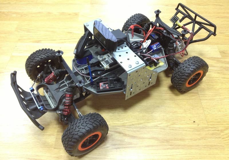
Fig. 1
At the same time, we did not try to completely recreate the real conditions of the road scene, eliminating all the charms of small-sized modeling.
To begin with, with simple examples, we wanted to work out the basic architectural components of the system (the base for obtaining a video stream and distributed processing on a combination of minicomputers and video cameras, like the prototype System – on – a – Chip (SoC)), which are potentially suitable for solving more complex problems.
We taught the robot to move along the corridor and detect simple objects, for example, an orange traffic cone. The task was that he could drive up to the object and stop. And then they decided to play with the ball. In the current version, if the ball is in the field of view of the camera, the robot detects the ball, accelerates and pushes it with a bumper. If the ball leaves the field of view of the camera, then the robot begins to search for it.
The video was shot during a report at the autumn conference of young scientists at MIPT,
right in the corridor of the main building
Now we are teaching the robot to go through the "snake" for a while. This exercise allows you to evaluate the quality of the control system and its progress from version to version. And also compare with the quality of manual control with human participation.
Initially, our robot contained only a control computer, a camera, and, in fact, a chassis. This is a model of a sports SUV Traxxas Slash 2wd made in a ratio of 1:10. ( Fig. 2 , Fig. 3 )

Fig. 2 Traxxas Slash 2wd
The chassis controller is based on the Arduino nano, but in fact, only the ATMega32 microcontroller is used from it.
A little later, we added a front sonar to the circuit to control the distance to obstacles - in other words, to prevent the robot from bumping into corners and walls.

Fig. 3 Traxxas Slash 2wd
If in the first version, the robot broadcast the video via HTTP back and the control signals were generated on the desktop, then in the current version 2.0 (shown in the video) the entire cycle is closed on board, and the main load on the video processing fell on the Odroid U2 minicomputer. ( Fig. 4-1 )
In addition to the computer, equipment version 2.0 includes:
- robot control device (Fig. 4-2);
- Logitech HD Pro C920 / Genius WideCam 1050 video camera (an almost arbitrary webcam can be used) (Fig. 4 -3);
- ASUS USB-N10 Wi-Fi adapter (Fig. 4 -4);
- USB hub (Figure 4-5)
- Sonar LV-MAXSONAR-EZ2 (Fig. 4-6)

Fig. 4
The functions of the robot control device include:
- implementation of control computer commands :
- generating PWM control signals,
- external load control (7 channels);
- processing signals from sensors :
- sonars (8 channels),
- Hall Sensor,
- battery voltage sensor (ADC);
- robot protection :
- frontal sonar emergency stop,
- stop upon loss of control signal.

Fig. 5 Robot equipment diagram
Now we are collecting the 3rd version. In it, the video stream capture system will already include two professional IDS video cameras, the video signal from which (including object detection) will be processed on separate minicomputers, which in turn are connected to the central minicomputer, which performs the final scene recognition and generation of control actions.
It is also planned to put several sonars around the perimeter of the robot in order to more fully represent the environment for solving parking problems.
A lot of improvements are planned for the future, for example, we want to hang lighting equipment similar to real cars on the robot, for which some of the parts are printed on a 3D printer. This is necessary to simulate the movement behind the car in front with the support of a certain distance (the case of movement in a dense stream or traffic jam).
The first lyrical digression.
By the way, if you do something like this, we immediately warn against the use of Chinese analogues - the first version of the motor controller was made on it, which resulted in several weeks of searching for the reasons for the strange behavior of the motor - it turned out that the microcontroller sometimes closed some inputs from the “analog” to the exits. Perhaps this is so lucky for us, but with the original Arduino there were no such problems.The second lyrical digression.
Before creating the chassis controller, it turned out that it was not known how and what to manage. The lack of official documentation on the control signals of the chassis components made it possible to recall the physics labs and dig deeper with the oscilloscope. As a result, it turned out that pulse-width modulation is used there. In general, nothing complicated.Third digression.
Somewhere between the detection of the problem and the assembly of the new controller, it was decided to abandon the circuit board on which the first controller was assembled, and therefore the “iron-printer” method of wiring the printed circuit boards was taken from naphthalene. The result was very neat and cool.The robot behavior algorithm for chasing a ball is presented schematically in the figure below. It seems that there is nothing incomprehensible in it. Is it worth saying a few words about the reversal algorithm. This is a refinement of the situation when the ball leaves the field of view of the robot. In fact, he has only 4 possibilities for a turn: forward to the right, forward to the left and back to the right and back to the left. The robot remembers where he saw the ball for the last time and turns in this direction in full analogy with a football player, from whose field of view the ball was lost. He seeks to turn in the direction where the ball flew.
For a reversal, we use the "asterisk" algorithm: we go, for example, first to the right and forward, then to the left and back, we get such arcs that are convex towards a common central point. This maneuver resembles a U-turn in a limited space, known to many by the exam in the traffic police ( Fig. 6 ).

Fig. 6
If a deadlock occurs due to the robot getting stuck, for example, catching on a chair leg, the control program identifies this situation due to the difference between the engine speed and the angle of rotation of the wheels. In this case, the robot tries to pass back, make a maneuver along the “asterisk” and continue moving towards the target.
Fourth lyrical digression.
When we were preparing for the conference of young scientists at the Moscow Institute of Physics and Technology, to increase the audience perception, we increased the parameter of acceleration. As a result, the robot began to run into obstacles more often, since the “stuck” case detection circuit stopped working adequately - the wheels began to slip. In addition, at a higher speed, the robot began to miss the ball more often (this can be seen in the first video). Therefore, we had to solve the problem of optimal balancing between the processing speeds of the video stream, robot movement and decision making. In terms of complexity, it resembled the problem of getting used to an old Soviet-made car with a manual gearbox, such as a Moskvich or Zhiguli, each of which had its own way to adjust the clutch and ignition. Whoever comes across this understands that it takes some time,
Fig. 7 Robot behavior algorithm for chasing a ball
In the third version of the robot (it is already almost complete), we switched to using a “professional” video camera and lens.

Fig. 8
At the same time, we are conducting experiments on installing cameras on rails, which are mounted on the rails of a full-size car ( Fig. 8 ). This will reproduce the real geometry and conditions of the road scene.
We plan to tell more about the new version of the robot in the next article.