Gamepad from Sega Mega Drive and Raspberry Pi Part 1 (preparatory and three-button)
If you played SMD games on an emulator, you probably noticed that the most convenient gamepad for these games is the SMD gamepad. For most other consoles, when playing on an emulator, it is possible to do with the same gamepad from Xbox or Logitech, the standard was formed around the end of the 90s. But until the end of the 90s, each of them as he could.
It is not difficult to buy a gamepad from SMD, and as a rule you can buy it where the clones of the prefixes themselves are sold, at a fairly affordable price, about 300 rubles.
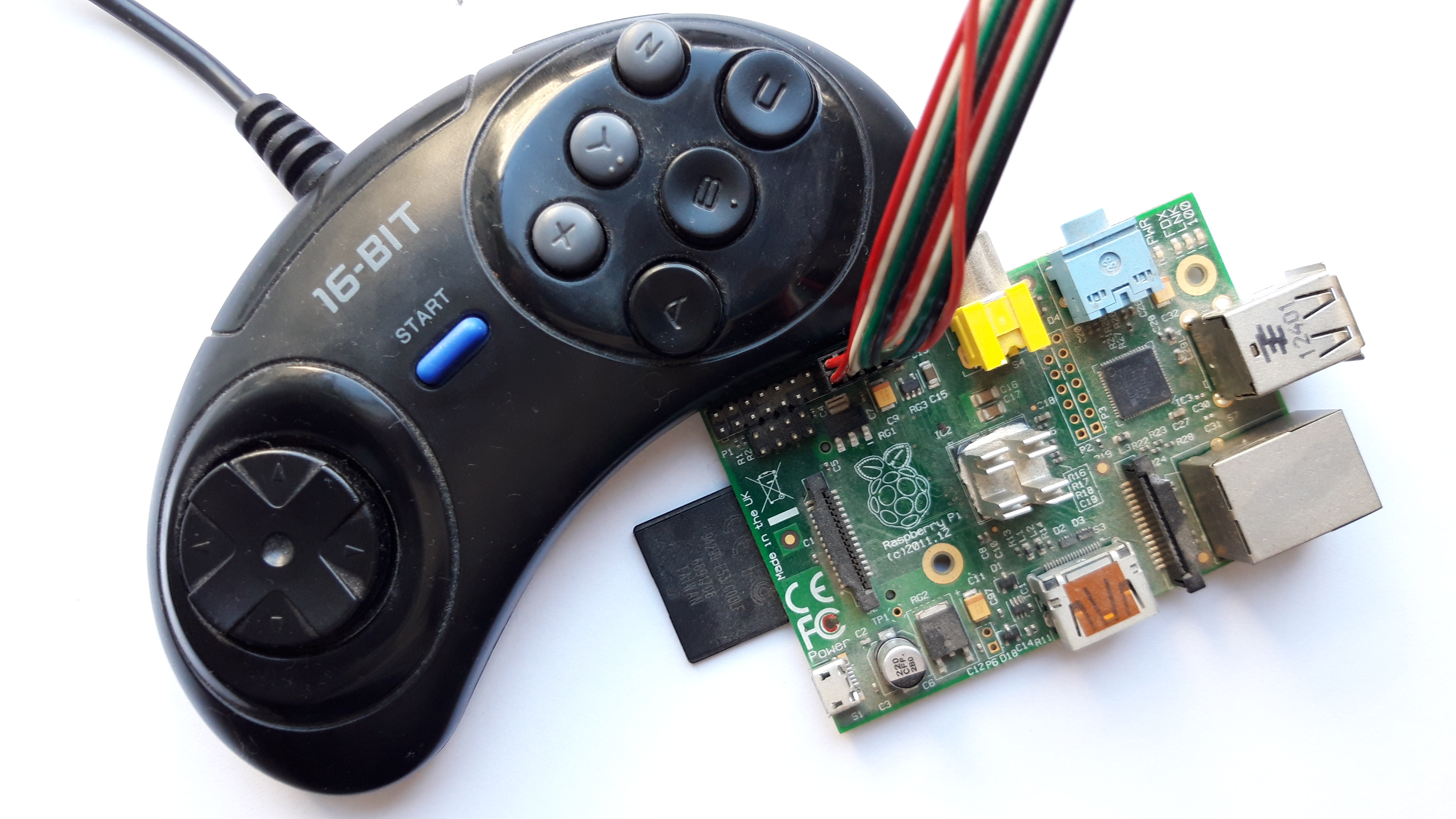
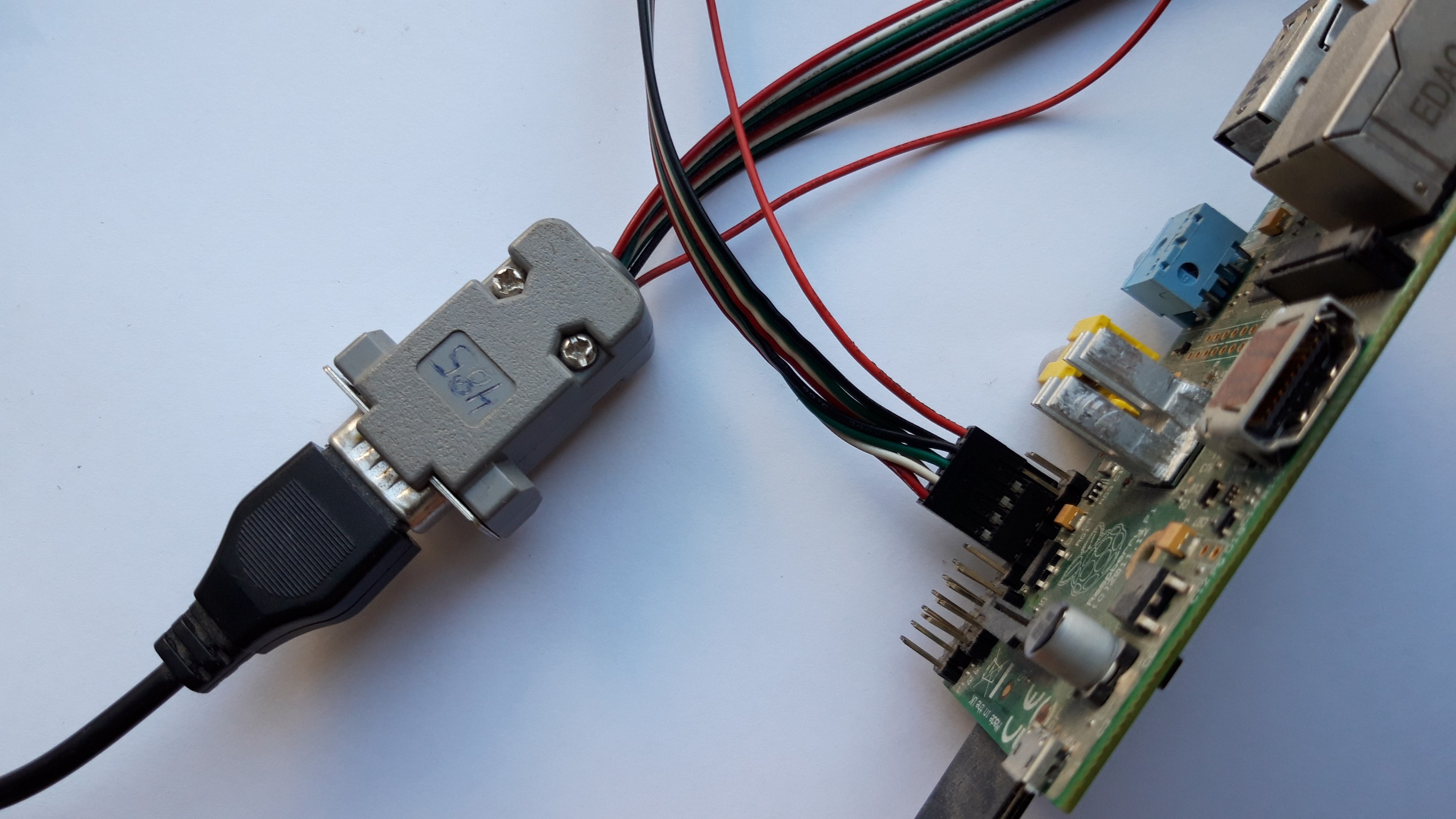
Connecting to the Raspberry pi, I, as before, organized with the help of a usb loop from the decommissioned case and the db-9 dad connector. And I wrote the conclusions of the GPIO in the program. The gamepad works great from 3.3 volts.
As always, there was a question about choosing an emulator, and the best option was the Picodrive emulator, it is optimized for ARM, well structured and as I understand it, it is part of the RetroPi assembly. But I had to tinker with the assembly. The source code is located on the Github service, at this address .
To build, we need 3 components of success from the emulator author's repository:
- Picodrive emulator itself;
- CPU emulator - cyclone68000;
- and FrontEnd - Libpicofe.
Now all this needs to be properly put together. Unpacking or not unpacking Picodrive , depending on how you downloaded it. Now open the directory with cyclone68000 , its contents must be copied to the directory:
/ваша директория/picodrive-master/cpu/cyclone
The same should be done with the contents of the Libpicofe directory , its contents are copied to the directory:
/ваша директория/picodrive-master/platform/libpicofe
Now it is necessary to execute preparation for assembly: we
make a configuration
sudo ./configure
After the configuration is completed, a file - config.mak will be created , in which it will be necessary to find and change some lines. Below is the finished result:
AS = arm-linux-as
LDLIBS += -L/usr/lib/arm-linux-gnueabihf -lSDL -lasound -lpng  -lm -lz -lwiringPi
ARCH = arm
PLATFORM = rpi1
Next, you need to edit the file - config.h . It is located in the directory:
/ваша директория/picodrive-master/cpu/cyclone
In it it is necessary to put down the ones in the variables:
#define HAVE_ARMv6 1#define CYCLONE_FOR_GENESIS 1And now the program part
As always, it was necessary to find a place where the information about the pressed buttons is processed, to understand
Without catching a suspense, I will immediately say that the files you are looking for are located in a directory:
/ваша директория/picodrive-master/pico/
Here we are interested in 3 files - pico.c , memory.c , memory.h . Probably you can do with a smaller number, and stuff everything in one, but it seemed so easier to me.
And so, in the pico.c file , I initialize the library and initial setup of the GPIO pins.
Immediately give part of the file header:
#include"pico_int.h"#include"sound/ym2612.h"#include<wiringPi.h>#define Data0 3#define Data1 4#define Data2 5#define Data3 12#define Data4 13#define Data5 10#define Select 6structPicoPico;structPicoMemPicoMem;
PicoInterface PicoIn;
As you can see, the heading of the WiringPi library is specified , and the defains are declared, which will be shown below. Well, for example, now in the void PicoInit (void) function :
voidPicoInit(void){
...
...
  PicoDraw2Init();
  wiringPiSetup ();
  pinMode (Select, OUTPUT);
  pinMode (Data0, INPUT);
  pinMode (Data1, INPUT);
  pinMode (Data2, INPUT);
  pinMode (Data3, INPUT);
  pinMode (Data4, INPUT);
  pinMode (Data5, INPUT);
  digitalWrite (Select, HIGH);
}
This is the emulator memory initialization function (sort of). And it was here that I inserted all the settings of the GPIO pins. Here is the pinout of the DB-9 connector .
Here it must be said that the gamepad has 6 information contacts (Data0 ... Data5), one manager (Select), and power.
Further, we define the same definitions, we need to repeat it again. This can be done both in memory.h and in memory.c . I chose the first option. It makes no sense to list this.
So we are getting to the most interesting - the memory.c file . It has 2 functions with eloquent names:
static u32 read_pad_3btn(int i, u32 out_bits)static u32 read_pad_6btn(int i, u32 out_bits)The names seem to unobtrusively hint at reading the status of 3-button and 6-button gamepads.
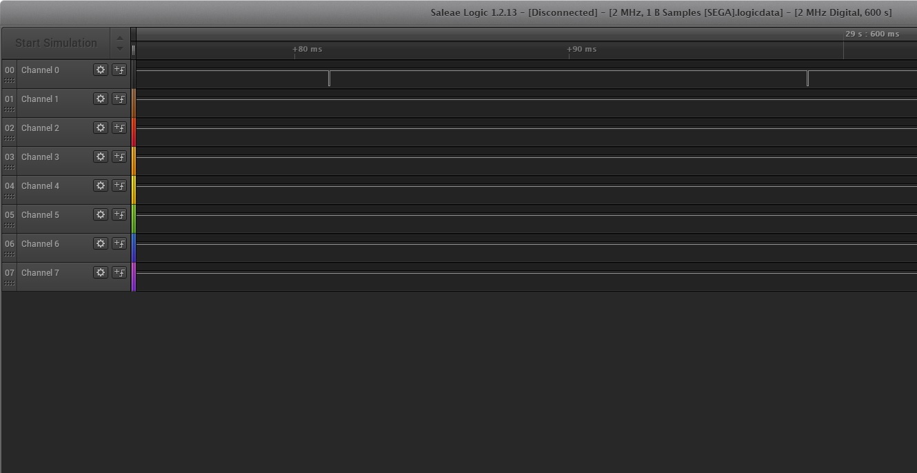
Here it is necessary to clarify that any 6-button gamepad can work as a 3-button. And the lion's part of the games works with this mode of the gamepad. In this mode, the state of the Select output changes once every 16 milliseconds. When Select = 0, the values of the buttons are read - UP, DOWN, A, Start. When Select = 1 reads the state of the buttons - UP, DOWN, LEFT, RIGHT, B, C. Below is an example of the operation of this mode.
Immediately give the listing of this function with the changes:
static u32 read_pad_3btn(int i, u32 out_bits){
    u32 pad = ~PicoIn.padInt[i]; // Get inverse of pad MXYZ SACB RLDU
    u32 value = 0;
    if (i == 0 && (out_bits & 0x40)) // TH
    {
      digitalWrite (Select, HIGH);
      delayMicroseconds (20);
      value ^= digitalRead(Data0) << 0; //read UP button
      value ^= digitalRead(Data1) << 1; //read DOWN button
      value ^= digitalRead(Data2) << 2; //read LEFT button
      value ^= digitalRead(Data3) << 3; //read RIGHT button
      value ^= digitalRead(Data4) << 4; //read B button
      value ^= digitalRead(Data5) << 5; //read C button
    }
    if (i == 0 && !(out_bits & 0x40))
    {
      digitalWrite (Select, LOW);
      delayMicroseconds (20);
      value ^= digitalRead(Data0) << 0; //read UP button
      value ^= digitalRead(Data1) << 1; //read DOWN button
      value ^= digitalRead(Data4) << 4; //read A button
      value ^= digitalRead(Data5) << 5; //read Start button
    }
    if (i == 1 && (out_bits & 0x40))// TH
    {
    value = pad & 0x3f;                      // ?1CB RLDU
    }
    if (i == 1 && !(out_bits & 0x40))
    {
    value = ((pad & 0xc0) >> 2) | (pad & 3); // ?0SA 00DU
    }
  return value;
}
Here i is the number of the gamepad, and the expression if (out_bits & 0x40) // TH is exactly responsible for the state of the Select output. It is worth noting that in the emulator the state of the buttons is given in the same form as in the console. Button pressed = 0.
Here is the result of the work:
Continuing in the next series, Pip-Pip-Pip