Assembling a laser projector from the available parts
UPD: Added board files from the DAC to GitHub.
Initially, I planned to make a Laser Harp , but so far I have an intermediate result - a device that can be used as a laser projector - to draw with a laser various shapes recorded in ILDA format files. I am aware that many who take on the assembly of a laser projector as a device controlling galvanometers (I still do not understand how to translate the “galvo scanner" combination into Russian) use cheap slightly modified sound cards for a computer. I went the other way since ultimately I will need a fully autonomous device that can work without a computer.
Let's see what my laser projector consists of. The cost of all parts amounted to about 8,000 rubles, of which more than half is a 70mW laser module.
My system uses the Stellaris Launchpad as the “brain” (because it is fast enough and has USB hardware support) and a 12-bit dual-channel DAC with the Analog Devices AD7249BRZ serial interface . To control the deviation of the beam to the driver input, you need to apply an analog signal in the range from -5 to 5 volts. DAC AD7249BRZ just knows how to work in this mode (as well as from 0 to 5 volts and from 0 to 10 volts). For him, I set up a special board in Eagle that connects to the Stellaris Launchpad. The board requires bipolar power, which is obtained using the ICL7660 chip. To convert the single output voltage of the power supply unit (15V) supplied with the galvanometers, I used the linear LM317 regulator, which later turned out to be not the most optimal solution, especially for powering the laser module - because the LM-ka with a large radiator (visible on video) after about 10 minutes of operation, it heats up to 70 degrees. Without a radiator, it just overheated very quickly and turned off from overheating (and with it the laser module, because of which I initially decided that it burned down and almost put down a couple of bricks, t .k. when it was re-energized, it did not turn on - as it later became clear until the microcircuit cools down).
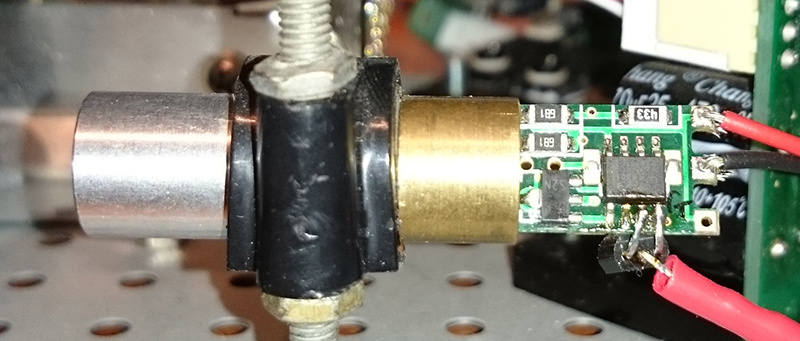
The laser module initially did not support TTL modulation, so when I was tired of just driving the laser in different directions, I thought about turning the beam on and off at the right times. To do this, it was necessary to modify the laser module with a soldering iron. Fortunately, almost all Chinese laser modules are very similar to each other, simple, and made on the LM358 operational amplifier. Soldering to his legs 3 and 4 (non-inverting input and ground, respectively) the emitter and collector of the first bipolar transistor 2N4401 that came across, I thus got the opportunity to modulate the laser by supplying a control signal to the base of the transistor:
The circuit and board for the AD7249BRZ is presented below. Perhaps an attentive reader will find an error in the circuit because, for reasons unknown to me, it seems that the part with the operational amplifier does not work, which is designed to make the output signal of the circuit balanced for greater protection against interference. My instance, instead of a balanced signal, produces an unbalanced one, but, nevertheless, everything works like that.
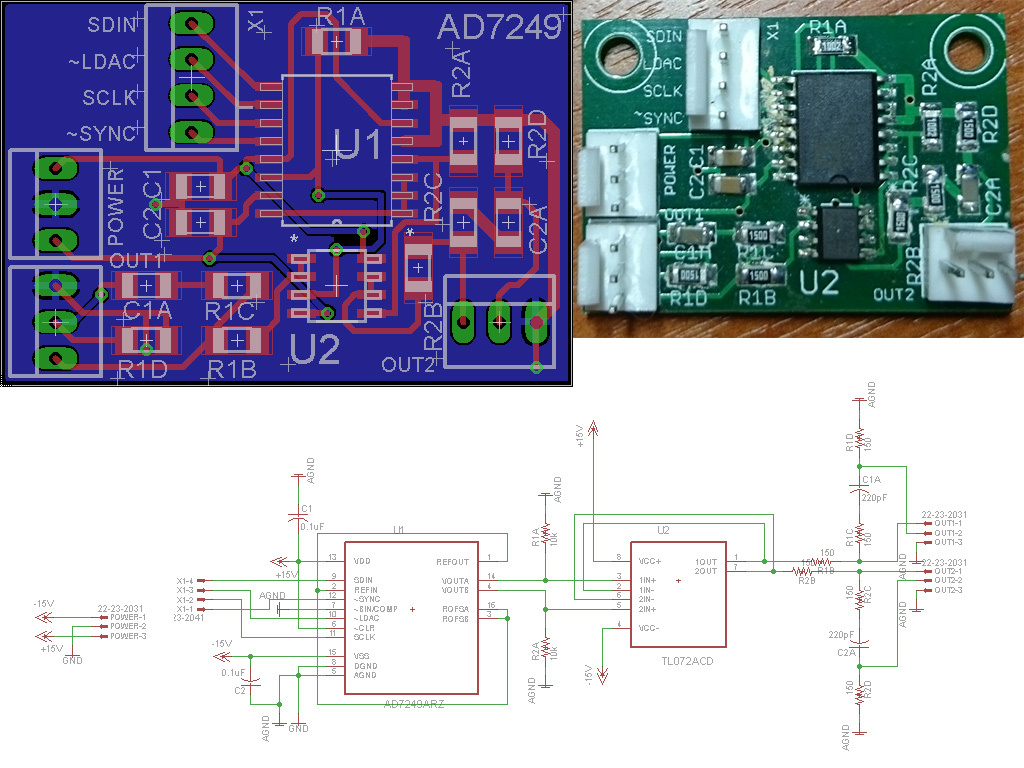
I hope you are not afraid of the scary picture of the board with a plaque at the terminals of the microcircuit, which was formed after wiping with ethyl alcohol. By the way, for this reason, it is recommended to wash the flux with isopropyl alcohol, since it does not leave such streaks. By the way, who is interested in what kind of connectors these are with a latch on the board - these are Molex connectors (22-23-2021 socket, 22-01-3027 plug, 08-50-0114 pin for the plug), I ordered them through Digikey, since among the Chinese they are somehow indecently expensive.
On this, it seems that the most interesting part about the iron part ends, so we turn to the software part. It consists of two parts - a program for a PC and firmware for Stellaris Launchpad, which implements a USB bulk device with its own packet format of 32 bits each. The sample format is described by the following structure:
The device uses USB buffers of 512 bytes in size, which records data from a PC with a certain margin, and at such a speed so as not to cause an overflow or underrun of the buffer. Used galvanometers are designed to display 20,000 points per second, that is, this is the required sampling frequency. In the function of processing data from USB, the processing speed is regulated using a commonplace

green LED on the video at the beginning of the post blinks after processing each pack of 20,000 samples. That is, ideally, it should blink exactly 1 time per second.
The software for the PC is based on the OpenLase
In the function
The full source code of the controller firmware can be viewed on GitHub .
In the future, it is planned to finish this to a state similar to the originally conceived laser harp. For this, one rather than two mirrors is sufficient, since the laser beam moves only along one axis. The principle of operation of the harp is that the controller ignites and extinguishes the laser beam at moments known to it, creating a laser "keyboard" in the air. The performer, blocking a bright laser beam with a hand in a reflective glove, activates the photosensitive element at the base of the “harp”. Since the microcontroller knows at what moment which part of the keyboard he “drew”, he can determine which of the rays was blocked. The next step is to generate the corresponding MIDI message and send it to a computer or a connected hardware synthesizer to generate sound.
Initially, I planned to make a Laser Harp , but so far I have an intermediate result - a device that can be used as a laser projector - to draw with a laser various shapes recorded in ILDA format files. I am aware that many who take on the assembly of a laser projector as a device controlling galvanometers (I still do not understand how to translate the “galvo scanner" combination into Russian) use cheap slightly modified sound cards for a computer. I went the other way since ultimately I will need a fully autonomous device that can work without a computer.
Let's see what my laser projector consists of. The cost of all parts amounted to about 8,000 rubles, of which more than half is a 70mW laser module.
- Galvanometers and drivers for them to deflect the laser beam along the X / Y axes
- 532nm 70mW 5V Laser Laser Module Dragon Lasers SGLM70
- Texas Instruments Stellaris Launchpad
- Home- made board with AD7249BRZ DAC
- Power Supply
Iron
My system uses the Stellaris Launchpad as the “brain” (because it is fast enough and has USB hardware support) and a 12-bit dual-channel DAC with the Analog Devices AD7249BRZ serial interface . To control the deviation of the beam to the driver input, you need to apply an analog signal in the range from -5 to 5 volts. DAC AD7249BRZ just knows how to work in this mode (as well as from 0 to 5 volts and from 0 to 10 volts). For him, I set up a special board in Eagle that connects to the Stellaris Launchpad. The board requires bipolar power, which is obtained using the ICL7660 chip. To convert the single output voltage of the power supply unit (15V) supplied with the galvanometers, I used the linear LM317 regulator, which later turned out to be not the most optimal solution, especially for powering the laser module - because the LM-ka with a large radiator (visible on video) after about 10 minutes of operation, it heats up to 70 degrees. Without a radiator, it just overheated very quickly and turned off from overheating (and with it the laser module, because of which I initially decided that it burned down and almost put down a couple of bricks, t .k. when it was re-energized, it did not turn on - as it later became clear until the microcircuit cools down).
The laser module initially did not support TTL modulation, so when I was tired of just driving the laser in different directions, I thought about turning the beam on and off at the right times. To do this, it was necessary to modify the laser module with a soldering iron. Fortunately, almost all Chinese laser modules are very similar to each other, simple, and made on the LM358 operational amplifier. Soldering to his legs 3 and 4 (non-inverting input and ground, respectively) the emitter and collector of the first bipolar transistor 2N4401 that came across, I thus got the opportunity to modulate the laser by supplying a control signal to the base of the transistor:
Laser Modified File
The circuit and board for the AD7249BRZ is presented below. Perhaps an attentive reader will find an error in the circuit because, for reasons unknown to me, it seems that the part with the operational amplifier does not work, which is designed to make the output signal of the circuit balanced for greater protection against interference. My instance, instead of a balanced signal, produces an unbalanced one, but, nevertheless, everything works like that.
I hope you are not afraid of the scary picture of the board with a plaque at the terminals of the microcircuit, which was formed after wiping with ethyl alcohol. By the way, for this reason, it is recommended to wash the flux with isopropyl alcohol, since it does not leave such streaks. By the way, who is interested in what kind of connectors these are with a latch on the board - these are Molex connectors (22-23-2021 socket, 22-01-3027 plug, 08-50-0114 pin for the plug), I ordered them through Digikey, since among the Chinese they are somehow indecently expensive.
Software
On this, it seems that the most interesting part about the iron part ends, so we turn to the software part. It consists of two parts - a program for a PC and firmware for Stellaris Launchpad, which implements a USB bulk device with its own packet format of 32 bits each. The sample format is described by the following structure:
typedef struct
{
	unsigned x:12; // координата X
	unsigned rx:4; // флаг (вкл/выкл лазер)
	unsigned y:12; // координата Y
	unsigned ry:4; // не используется
} sample_t;
The device uses USB buffers of 512 bytes in size, which records data from a PC with a certain margin, and at such a speed so as not to cause an overflow or underrun of the buffer. Used galvanometers are designed to display 20,000 points per second, that is, this is the required sampling frequency. In the function of processing data from USB, the processing speed is regulated using a commonplace
SysCtlDelay. By adjusting the value, you can adjust the system so that the ILDA test picture is displayed correctly: The green LED on the video at the beginning of the post blinks after processing each pack of 20,000 samples. That is, ideally, it should blink exactly 1 time per second.
The software for the PC is based on the OpenLase
playilda.c package, however, everything superfluous was cut out from there and instead of interacting with the JACK server, libusb is used to send data packets to the Stellaris Launchpad.Source code for PC
#include
#include
#include
#include
#include
#include
#include
#include
#include
#define MAGIC 0x41444C49
static inline uint16_t swapshort(uint16_t v) {
	return (v >> 8) | (v << 8);
}
float scale = 1.0;
typedef struct {
	uint32_t	magic;
	uint8_t		pad1[3];
	uint8_t		format;
	char		name[8];
	char		company[8];
	uint16_t 	count;
	uint16_t 	frameno;
	uint16_t 	framecount;
	uint8_t		scanner;
	uint8_t 	pad2;
} __attribute__((packed)) ilda_hdr;
#define BLANK 0x40
#define LAST  0x80
typedef struct {
	int16_t x;
	int16_t y;
	int16_t z;
	uint8_t state;
	uint8_t color;
} __attribute__((packed)) icoord3d;
typedef struct coord3d {
	int16_t x;
	int16_t y;
	int16_t z;
	uint8_t state;
	coord3d(int16_t x, int16_t y, int16_t z, uint8_t state) : x(x), y(y), z(z), state(state) { }
} coord3d;
typedef struct {
	std::vector points;
	int position;
} frame;
frame rframe;
int subpos;
int divider = 1;
int loadildahdr(FILE *ild, ilda_hdr & hdr)
{
	if (fread(&hdr, sizeof(hdr), 1, ild) != 1) {
		std::cerr << "Error while reading header" << std::endl;
		return -1;
	}
	if (hdr.magic != MAGIC) {
		std::cerr << "Invalid magic" << std::endl;
		return -1;
	}
	if (hdr.format != 0) {
		fprintf(stderr, "Unsupported section type %d\n", hdr.format);
		return -1;
	}
	hdr.count = swapshort(hdr.count);
	hdr.frameno = swapshort(hdr.frameno);
	hdr.framecount = swapshort(hdr.framecount);
}
int loadild(const std::string & file, frame & frame)
{
	int i;
	FILE *ild = fopen(file.c_str(), "rb");
	if (!ild) {
		std::cerr << "Cannot open " << file << std::endl;
		return -1;
	}
	ilda_hdr hdr;
	loadildahdr(ild, hdr);
	for (int f = 0; f < hdr.framecount; f++)
	{
		std::cout << "Frame " << hdr.frameno << " of " << hdr.framecount << " " << hdr.count << " points" << std::endl;
		icoord3d *tmp = (icoord3d*)calloc(hdr.count, sizeof(icoord3d));
		if (fread(tmp, sizeof(icoord3d), hdr.count, ild) != hdr.count) {
			std::cerr << "Error while reading frame" << std::endl;
			return -1;
		}
		for(i = 0; i < hdr.count; i++) {
			coord3d point(swapshort(tmp[i].x), swapshort(tmp[i].y), swapshort(tmp[i].z), tmp[i].state);
			frame.points.push_back(point);
		}
		free(tmp);
		loadildahdr(ild, hdr);
	}
	fclose(ild);
	return 0;
}
short outBuffer[128];
int process()
{
	frame *frame = &rframe;
	short *sx = &outBuffer[0];
	short *sy = &outBuffer[1];
	for (int frm = 0; frm < 64; frm++) {
		struct coord3d *c = &frame->points[frame->position];
		*sx = 4095 - (2047 + (2048 * c->x / 32768)) * scale;
		*sy = (2047 + (2048 * c->y / 32768)) * scale;
		if(c->state & BLANK) {
			*sx |= 1 << 15;
		} else {
			*sx &= ~(1 << 15);
		}
		sx += 2;
		sy += 2;
		subpos++;
		if (subpos == divider) {
			subpos = 0;
			if (c->state & LAST)
				frame->position = 0;
			else
				frame->position = (frame->position + 1) % frame->points.size();
		}
	}
	return 0;
}
int main(int argc, char **argv)
{
	libusb_device_handle *dev;
	libusb_context *ctx = NULL;
	int ret, actual;
	ret = libusb_init(&ctx);
	if(ret < 0) {
		fprintf(stderr,"Couldn't initialize libusb\n");
		return EXIT_FAILURE;
	}
	libusb_set_debug(ctx, 3);
	dev = libusb_open_device_with_vid_pid(ctx, 0x1cbe, 0x0003);
	if(dev == NULL) {
		fprintf(stderr, "Cannot open device\n");
		return EXIT_FAILURE;
	}
	else
		printf("Device opened\n");
	if(libusb_kernel_driver_active(dev, 0) == 1) {
		fprintf(stderr, "Kernel driver active\n");
		libusb_detach_kernel_driver(dev, 0);
	}
	ret = libusb_claim_interface(dev, 0);
	if(ret < 0) {
		fprintf(stderr, "Couldn't claim interface\n");
		return EXIT_FAILURE;
	}
	// To maintain our sample rate
	struct timespec ts;
	ts.tv_sec  = 0;
	ts.tv_nsec = 2000000;
	memset(&rframe, 0, sizeof(frame));
	if (loadild(argv[1], rframe) < 0)
	{
		fprintf(stderr, "Failed to load ILDA\n");
		return EXIT_FAILURE;
	}
	while(1)
	{
		process();
		if(nanosleep(&ts, NULL) != 0)
			fprintf(stderr, "Nanosleep failed");
		ret = libusb_bulk_transfer(dev, (1 | LIBUSB_ENDPOINT_OUT), (unsigned char*)&outBuffer, 256, &actual, 0);
		if(ret != 0 || actual != 256)
			fprintf(stderr, "Write error\n");
	}
	libusb_release_interface(dev, 0);
	libusb_close(dev);
	libusb_exit(ctx);
	return 0;
}
In the function
main(), nanosleep also controls the frequency with which new data is sent to the microcontroller. The full source code of the controller firmware can be viewed on GitHub .
Future plans
In the future, it is planned to finish this to a state similar to the originally conceived laser harp. For this, one rather than two mirrors is sufficient, since the laser beam moves only along one axis. The principle of operation of the harp is that the controller ignites and extinguishes the laser beam at moments known to it, creating a laser "keyboard" in the air. The performer, blocking a bright laser beam with a hand in a reflective glove, activates the photosensitive element at the base of the “harp”. Since the microcontroller knows at what moment which part of the keyboard he “drew”, he can determine which of the rays was blocked. The next step is to generate the corresponding MIDI message and send it to a computer or a connected hardware synthesizer to generate sound.