Creating characters in Blender and Unity
- Transfer
Visually, 3D game characters are simulated using models, textures, and animations.
In the past, to use the same animations, characters had to have completely identical skeletons. This limited the variety of characters, because their growth and proportions also had to be the same. For example, in old FIFA games, all players had the same size, because creating a separate skeleton and a set of animations would turn into a real nightmare.
Fortunately for game developers, today most engines have a system that allows you to reuse animations, provided the skeletal hierarchy is compatible. This system allows you to use the same animation for characters of all shapes and sizes. In Unity, this system is calledMecanim . It provides a convenient setting of animations, mixing between them and the transfer of humanoid animations between models.
The ability to reuse animations allows you to use animations from the Asset store and from websites such as mixamo.com for your own characters. It saves a lot of time!
In this tutorial, you will learn how to prepare a humanoid model in Blender and how to transfer it to Unity. In particular, you will learn the following:
- Create the armature (skeleton) of the character and perform its rigging (binding the skeleton to the mesh)
- Modify the character by adding accessories and objects
- Export Model to FBX
- Import Blender Models
- Create and customize a humanoid avatar
- Attach objects to character
- Animate a humanoid in Unity
Getting Started
To complete this tutorial you need the following:
- Install the latest stable version of Unity .
- Install the latest stable 64-bit version of Blender .
- Have a minimal understanding of the Unity editor. You can learn tutorials for beginners on our website.
- Experience with Blender is recommended. There are tutorials on which you can learn the basics.
Download the source materials and unpack them somewhere.
Open the project starter folder and navigate to the Assets \ RW \ Models folder . Open the CuteCharacter.blend file in Blender .
The file contains the following data:
- Low poly model of a humanoid character.
- Material CuteCharacter .
- Link to the CuteBase texture contained in the same folder as the model.
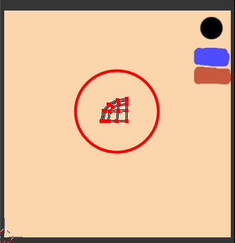
Opening the file, you should see the character model on the left:
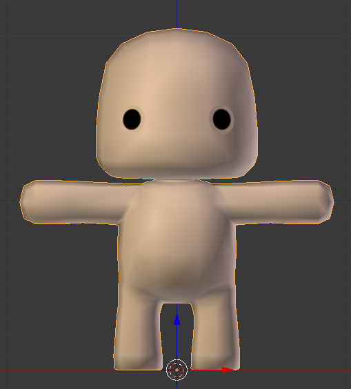
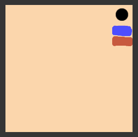
Note that it is mirrored on the X axis, it will greatly simplify the entire process of work. On the right is a simple image of the loaded texture:
The first step to animating this character is to perform rigging.
Create character rig
Rigging is the creation of an armature, a skeleton of a model. The armature has several connected bones to which vertices can be attached so that they move as the bone moves.
Move the mouse to the 3D View window to switch focus to it. Then add a new armature - hold Shift and press A to open Add Menu . Choose Armature> Single Bone .
We created the armature and its very first bone, which is also called the root bone. Without removing the selection from the reinforcement, find the X-Ray checkbox in the Display section of the Properties tab and check it.
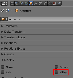
Now the armature will be visible through the character. This will simplify the creation of the skeleton.
Before you start creating a complete structure, it is important to understand how it should be configured to be compatible with the Humanity Avatar Unity engine.
Due to the peculiarities of binding the bones to their own Unity system, some key bones are mandatory.
Unity expects at least 15 bones, namely:
- Hips (root bone) - pelvis
- Lower spine - the lower part of the spine
- Upper spine - the upper part of the spine
- Neck - neck
- Head - head
- Two upper arms - two shoulders
- Two lower arms - two forearms
- Two hands - two hands
- Two upper legs - two hips
- Two lower legs - two shins
The rig we create will contain all the bones listed above, as well as several additional bones to increase stability during animation.
Make sure the armature is still highlighted and press Tab to go to Edit mode . Select the root bone by clicking on it with the right mouse button .
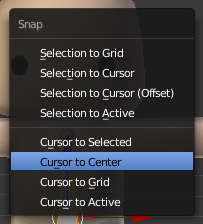
Note: in Blender, the right mouse button is used to select objects . Pressing the left mouse button changes the position of the 3D cursor - a small yellow circle with a red and white ring around. When you move the 3D cursor, all new objects are created in its new position, but for our tutorial this is not required. To reset the position of the 3D cursor, you can press Shift + S , the Snap Menu menu will open , and then select Cursor to Center .
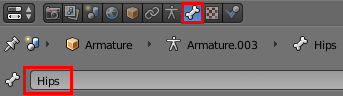
Open the Bone tab in the Properties panel on the right so that you can quickly make changes, and rename the root bone to Hips by typing the name in the name field and pressing Enter .
Spine
It's time to create the structure of the bones!
Select the bottom bone of the Hips bone and click in order G , Z , 0.5 and Enter to move it to where the navel should be.
Now select the top sphere and press G , Z , 0.1 and Enter to move it up a little.
Note: if you can hardly see what is happening, then you can approach and move away with the mouse wheel .
To create multiple spinal bones, we need to subdivide the Hips bone into three parts. Select Bone Hips , press W to open the Specials menu and select Subdivide . By default, this operation divides the bone into two parts, so change the value of Number of Cuts in the lower part of the Toolbar on the left to 2 .
Note: if you do not see the Number of Cuts slider , then move the mouse cursor under the Subdivide Multi text at the bottom left and scroll up to make it visible.
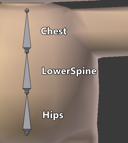
After separation of the spine, new bones are called Hips.001 and Hips.002 . This is a bad way of naming bones; rename the bones by highlighting them in turn and changing the name in the right pane of Bone .
Name the upper Chest , and the average LowerSpine .
Legs
We now turn to the bones of the legs. Duplicate the Hips bone by selecting it and pressing Shift + D , and then press the right mouse button to confirm .
If you look at the Bone panel on the right, you can see that a bone with the name Hips.001 is selected . Rename it to UpperLeg.L . L means left, "left." So we will understand which side of the bones we are from and this will help us in the future when mirroring.
Rotate the UpperLeg.L bone in the Y axis by pressing R , Y , 180 and Enter .
Now move to the horizontal position by pressing G , X , .23 and Enter . Then press G , Z , -.2 and Enter to move it vertically.
Note: The picture above shows wireframe mode to emphasize where the bone is. Enable or disable this mode by pressing on the Z .
Select the bottom sphere (also called a connector) and move it down by pressing G , Z , -.3 and Enter .

To leg could bend, it must be divided. Select the UpperLeg.L bone , press W and select Subdivide to split the legs into two parts. As a result, we will have two leg bones; name lower LowerLeg.L .
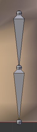
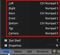
The last part of the legs is the feet. Switch to the side view by pressing 3 on the alphanumeric block (Numpad), then press the dot key ( . ) To focus on the tibia.
Note: if there is no alphanumeric block on the keyboard, you can switch between views by pressing the View button at the bottom of the screen.
Move away a little to see a large part of the leg.
Now select the bottom connector and to create a foot, extrude it by pressing E , Y , -.18 and Enter .
Rename the created bone to Foot.L in the Bone panel.
Now it would be nice to save the file. Press CTRL + S and left-click on the file name that appears. Periodically save your work, Blender is a fairly stable application, but sometimes it can crash.

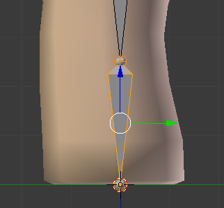
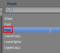
Return to the front view by pressing 1 on the alphanumeric box. Before moving on to the head, we need to make the pelvis a parent bone for the leg. Fortunately, it's pretty easy to do!
Select UpperLeg.L and find the drop-down list Parent in the Relations section of the Bone panel . Click on it and select Hips .
Body
Get down to the head! Select the connector at the top of the bone Chest , press E , Z , .055 and Enter . This will be a neck bone, so name it in the Bone Neck panel .
To add a head bone, do not deselect the top connector and press E , Z , .95 and Enter .
Name the created bone Head .
Next we proceed to the connector of the left shoulder. Select the top bone connector Chest and press E , X , .08 and Enter to add a new bone. Move it down a bit by selecting the right connector and pressing G , Z , -.09 and Enter .
Call this bone ShoulderConnector.L . This bone will attach the shoulder to the sternum. For the protocol: this is by no means anatomically correct, but we do not need it.
Select the rightmost connector again and press E , X , .85 and Enter . So we will create one big bone that will need to be split to create the remaining bones on the left side.
Select the created bone, press W and select Subdivide . Change the number of cuts on the bottom left for 3 to get four pieces.
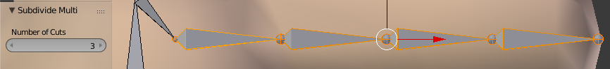
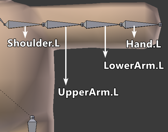
Name these bones as follows, starting from left to right:
- Shoulder.L
- UpperArm.L
- LowerArm.L
- Hand.L
At first glance, the current location of these bones looks good, but because of how the connector is located between the parts of the arm (it can be called an elbow), the arm will not be able to bend properly. Press Z to switch to wireframe mode, and see for yourself:
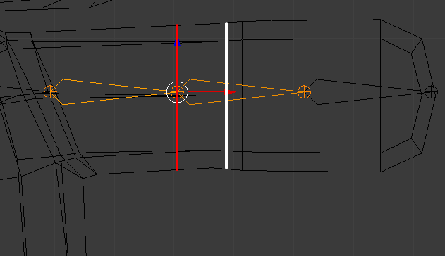
The red line indicates where the elbow is now, and the white line indicates the point where the arm is at the mesh. To fix this, select LowerArm.L and move it to the right by pressing G , X , .09 and Enter .
While we work only with the left part. But what about the right one?
I do not know about you, but I would use any opportunity to simplify my work. Therefore, the next step is to mirror the bones from left to right by pressing just a few keys.
Mirroring
Since version 2.79, Blender has a handy new feature for quick mirroring of reinforcement bones in just a few simple steps! Before the appearance of this function, it was necessary to duplicate, mirror manually, change the names and set the roles of the bones. If you have ever done this, then you know how long it is.
To begin, deselect all bones by pressing A , so that there is no orange outline of the selections left.
Next, select the bones only on the left side (the left side of the character is on your right), holding Shift and right-clicking each bone. Do not forget the foot!
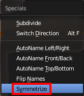
After selecting these bones, press W and select Symmetrize .
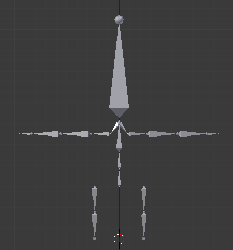
And this is enough to get the perfect mirror version of the selected bones:
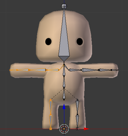
In addition, at the end of the names of the bones, instead of .L, the letter .R stands for their position.
Save the file and get ready for rigging.
Drawing weights
Drawing weights (Weight painting) is the process of attaching bones to a 3D mesh. Each bone is attached to a group of vertices with a certain amount of weight .
Weight determines the "stiffness" of pulling vertices behind the bone.
Performing this task manually can take a long time, because you have to draw the weight of each individual bone yourself. Fortunately, Blender can take over the bulk of the routine work by automatically drawing weights depending on the proximity of the bones to the vertices.
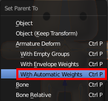
Press Tab to switch to Object mode. First select a model, then hold Shift and right- click on the valve to select it too.
Now press CTRL + P to open the Parent menu and select With Automatic Weights to make the model a parent for the armature and automatically draw the scales.
Visually, the difference may not be noticeable, but now the bones are attached to the mesh.
Before testing, make sure that the Pivot Point is in Median Point mode by checking the bottom panel:
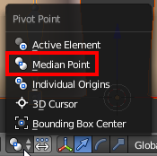
Turn on Median Point mode if 3D Cursor mode is still selected .
And now the interesting begins! Switch to Pose mode , select a bone and rotate it by pressing R and moving the mouse cursor. Do this with each bone in the center and the left side of the model to make sure that all the weights are assigned correctly.
Rotate the viewing window in different directions and check the rotation from different angles by pressing the mouse wheel and moving the mouse in different directions.
After checking all the bones, you may notice that the eyes do not move with the head, which looks a bit strange, if not more:
To attach the eyes to the head, we still have to assign weights. Do not exit the Pose mode of the armature, hold Shift and press RMB on the model to also select it. Now go to the Weight Paint mode . We are ready to draw weights.
In this mode, you can select bones by holding CTRL and clicking RMB on the bone. Select the Head bone and turn it back by pressing R , X , -90 and Enter .
To attach the eyes to the Head bone , select the Add brush in the Brush section of the Toolbar on the left.
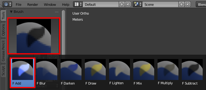
Press Z to switch to wireframe mode and rotate the viewport so that at least one of the eyes is no longer on the front of the head. Now color the tops of the eyes to increase the weight until the eyes stop hanging in the air.
Weight can be seen visually by color on the mesh; values range from 0 (dark blue) to 1 (bright red). To check the results, return to the front view by pressing numpad 1 and Alt (or Option) + R to reset the Head bone rotation .
Now the eyes are properly attached to the head.
Note: the rotation shown above is made by rotating the trackball . This rotation mode can be activated by pressing R again after the start of rotation.
Having completed the basic drawing of the scales, you can proceed to the details.
Add accessories
Accessories in this context are objects attached to a character, but not part of his body. In this section, we will look at two ways of attaching objects: to the model itself and as a separate, reusable object attached to the bone.
The first method can be used for hats, the second - for the weapon that holds the character.
First we press Z to exit wireframe mode and press A , and then Alt (or Option) + R to reset the rotation of all bones.
Character editing
The first way to add details to a character is easier, but it imposes certain limitations. When working with the model itself, which is mirrored, all the added geometry will be copied from the left side to the right side, and vice versa. Therefore, it is impossible to add something unique to one of the parties. Since geometry is part of this particular model, it also cannot be reused for other characters. This method is ideal for any situation in which such restrictions are not a problem.
If you repeated tutorial actions after me, now you are in in Weight Paint mode . And this is good, because after adding the hat, we need to start drawing weights again. Press tabto switch to Edit mode and start by switching the selection mode to Vertex by pressing CTRL + Tab and selecting Vertex from the menu .
Now, RMB select any vertex in the upper part of the head that is above the red line (which is the UV-stitch used for texturing ). Press CTRL + L to select all attached vertices, so we will select the entire model. Now select UV delimiter , choosing> UVs in the bottom left pane.
Now only the top of the head will be selected.
Also select the edge loop beneath it by holding Shift and Alt (or the Option) , and then pressing RMB on any of the first horizontal ribs below.
Now duplicate the selected faces by pressing Shift + D and then Enter . Move the duplicated faces slightly by pressing G , Z and 0.01 .
Then scale everything selected by pressing S , 1.05 and Enter .
So we’ll move the hat off the head a bit to avoid Z-facet conflict.
The hat is similar to a piece of the body hanging in the air, so in order to attach it to the body, we will do the following:
- Select only the bottom row of “hats”: press A to deselect everything, then hold Alt (or Option) and right- click on one of the lower edges.
- Make them flat by pressing S , Z and 0 .
- Press E to extrude and Enter to confirm.
- Press S to start scaling and move the cursor to the model until the edges are inside the head. Rotate the viewport to make it easier to see. Press Enter to confirm scaling.
This will give the hat a little depth so that it looks good from all sides and there are no holes in it. However, a hat made of human skin is not exactly what we would like. To change the color, we first need to expand its UV-coordinates so that they lie beautifully on the texture.
Select all the hat, by selecting any of its top and pressing the CTRL + of L . This time, change the limiter to Normal to select all connected vertices.
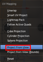
For our hat, we will perform one of the simplest developments in the world: from view. Press numpad 1 to go to the front view, then press U to open the Unwrap menu and select Project From View .
If you look at the right side of the Blender window, which shows the texture, you will notice that there have been added several peaks that look like half a hat:
You can select all the vertices by moving the mouse and clicking on the texture A . Blender actions are context sensitive and depend on the location of the cursor, so let it still be inside this texture area.
Now press G to move the UV to the blue spot, confirm the movement by pressing Enter , and then scale the selected one to fit within the blue area: press S and confirm with Enter .
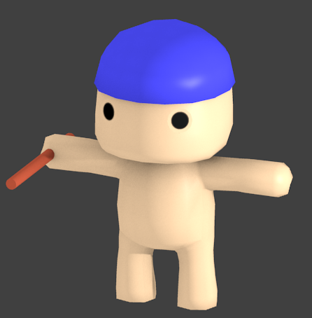
If you now look at the character, you can see that his hat has turned blue.

You can change the image texture to make any other color.
Now again move the cursor to the left, next to the model and press Tab to return to Weight Paint mode . Turn the Head bone slightly to check if the hat is attached.
Looks like we got lucky! As the top of the hat is close to the Head bone , they are added automatically. If this did not happen, we would have to paint the hat by hand, as we did with the eyes.
Now we look at the creation and attachment of a separate object.
Attaching Objects
In this section, we will create a small staff that will be the weapon in the hands of the character. Instead, you can easily imagine a sword, an ax, or even a magic wand, but in this tutorial we will not consider the creation of sophisticated weapons.
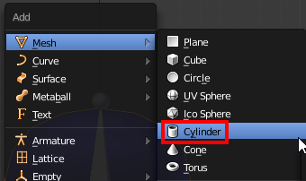
Switch to Object mode and press Shift + A to open the Add menu . Select Mesh> Cylinder to add a new cylinder to the scene.
The default cylinder is too large, so let's adjust its parameters in the lower left corner: change the Radius to 0.04 , and the Depth to 1.2 .
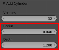
Due to this, the cylinder will be thinner and shorter.
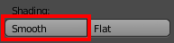
Make the cylinder smooth by clicking on the Smooth button in the Shading section of the Tool Shelf panel on the left.
No material has been assigned to our cylinder yet. To assign a material, open the Material tab in the Properties panel on the right and select CuteMaterial from the drop-down list next to the New button.

To turn the cylinder into a brown staff, we first need to do a UV scan. Press Tab to go to Edit mode, press U to open the Unwrap menu , and select Project From View .
Move the mouse over the texture on the right; press G to move the UV to the brown piece of the texture. Confirm the movement with the Enter key and zoom out by pressing S and moving the mouse so that the UV fits inside this piece.
Now the staff has turned brown. Do not worry about the wrong location, soon we will deal with them.
Open the Constraints tab of the Properties panel. Add a new constraint (constraint) by clicking on the Add Object Constraint drop-down list and selecting Child Of .
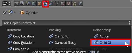
Constraints are used to limit the position, rotation and scale of an object. In our case, I made the cylinder a child of the character's bone. Due to this, when creating animations, the object will be permanently attached to the hand. This greatly simplifies the preview of the animation and allows you to limit the intersection of the object with the body.
Setting a limit is very simple. Click on the Target drop-down list and select Armature . Now click on the drop-down list of Vertex Group and select Hand.R .
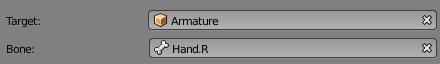
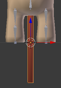
After that you will notice that the staff instantly attached to the character’s right hand. However, his position and turn are not entirely correct. Rotate the staff on the Z axis by 90 degrees by pressing R , X , 90, and Enter . Now move it forward a bit by pressing G , Y , -0.4 and Enter . So much better!
It's time to try the staff. Return to Object mode by pressing Tab , select the armature and switch to Pose mode using the drop-down list at the bottom of the screen. Rotate the viewport so that you can clearly see the staff, select UpperArm.R and rotate it slightly by pressing R and moving the mouse. The staff will follow the hand as if the character is holding it.
The character and his accessories are ready. Save the file, our work is finished here.
Now we will be engaged in export of model and armature in Unity.
Export to other formats
Note: if you are not interested in exporting models to other formats in order to share them with people, you can skip this section. Just save the file and close Blender.
Unity works quite well with the Blender application's .blend format if Blender is installed on the system. However, when transferring models to other people, it is better to use formats like .FBX or .OBJ, which do not require any third-party software. It is for this reason that most of our tutorials use the model files in .FBX, and not the original .blend.
Exporting to FBX from Blender is easy. To start, select File> Export> FBX (.fbx) in the top menu .
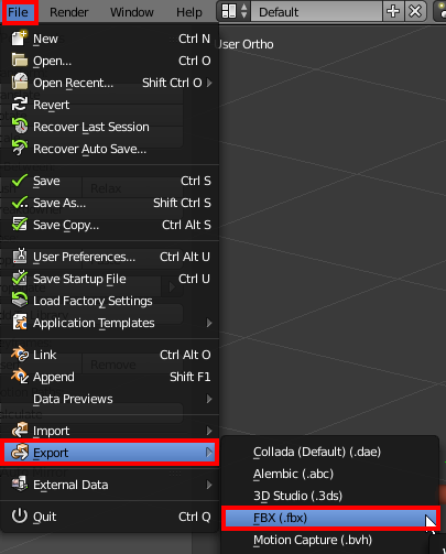
You will see the export mode. Unlike most applications, Blender does not open a separate window, but instead replaces the contents of the entire window.
You can select the location to save the file by selecting the folder on the left or by entering the location in the field above. Export options are located in the lower left corner of the window:
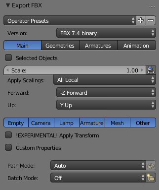
These default export options are suitable for Unity, but there is a possibility that they may create chaos in more complex scenes, because they export everything, even lights and cameras. To make the export clean, make the following changes:
Deselect the Camera , Lamp, and Other . This can be done by holding Shift and clicking on the options that you want to disable.
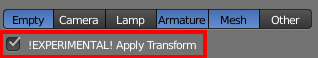
If only such options are selected, no unwanted objects are exported. Now check the box ! EXPERIMENTAL! Apply Transform under these options. He will apply the position, rotation and scale of all objects. This means that non-uniform values will be reset; for example, if the rotation had values (X: 23, Y: 125, Z: 7) , then it would be reset to (X: 0, Y: 0, Z: 0) .
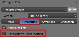
Switch to the Geometries tab by clicking on the Geometries button and uncheck the Use Modifiers Render Setting box . This will keep the high number of polygons inside for rendering in Blender, but will leave it low inside Unity.
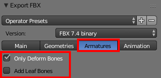
Next, open the Armatures tab , check the Only Deform Bones box and uncheck Add Leaf Bones . This prevents the Blender application from adding extra bones to the armature. Leaf bones are only required for compatibility with Maya. Non-deform bones, for example, controlling bones, are only needed in the simulation software to perform fine tuning; in game engines like Unity, they are useless.
Options Animation by default are set up correctly, so do not need to change them.
Having set all this up, it would be too boring every time to do it every time you export a file. And here presets will help us. We can save all these parameters to the internal Blender options for future use.
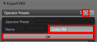
To do this, click on the + button next to the Operator Presets drop-down list , enter the name of the preset in the text box, and click on the OK button . In this tutorial we will call it Unity FBX .
If you open the Operator Presets drop-down list , you can select the preset that you just created:
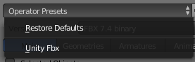
After that, the parameters will be instantly applied. Presets work for all files, so now you can easily export any Blender file to FBX for use with Unity.
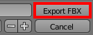
The last step is the export itself. In this tutorial, the .blend file is used in Unity for animation, so save the FBX file to any location by selecting the folder on the left and clicking the Export FBX button in the upper right corner.
Save the file and close Blender. Finally it is time to go to Unity and use our model.
Humanoid setting
Open the project stub in Unity and look at the Project window .
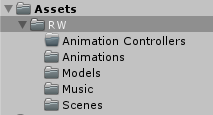
Here is a brief description of the folders:
- Animation Controllers : Used to insert a character animation controller.
- Animations : contains simple wait animations.
- Models : here we edited and saved the character. Also in this folder is a dojo model and several textures.
- Music : A simple Chinese melody corresponding to the dojo style.
- Scenes : Dojo Scene.
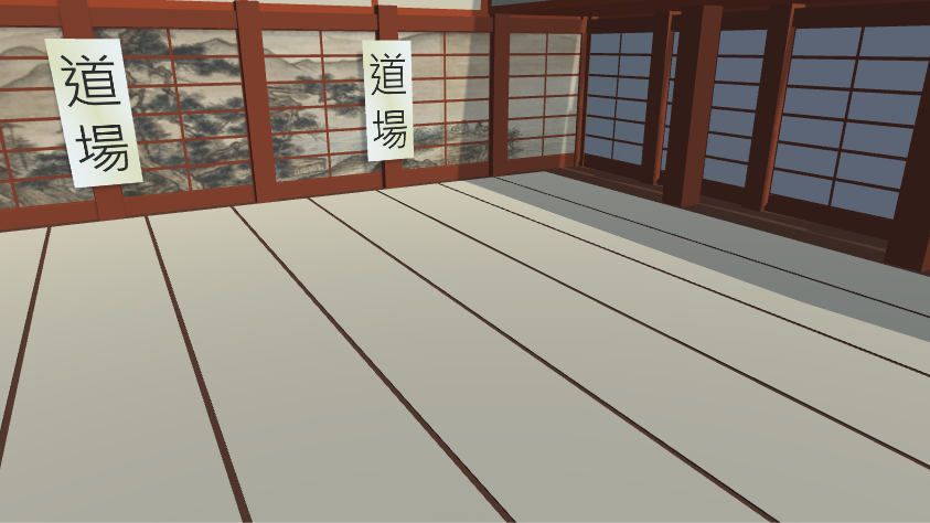
If the Dojo scene is not yet open, then open it from the Scenes folder . The scene is the interior of a dojo with an audio source that reproduces background music.
Having dealt with this, let's start using the character!
Snapping avatar
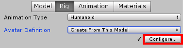
First, select the CuteCharacter model from the Models folder and open the Rig tab in the Inspector . Open the Animation Type drop-down menu and select Humanoid .
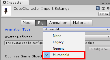
So we’ll let you know that the character is a humanoid so that Unity can use it accordingly. Now click Apply to save these settings.
After a brief re-import, you will notice that the Configure ... button has appeared . Click on it to start binding the bones to the Unity 'Mecanim system.
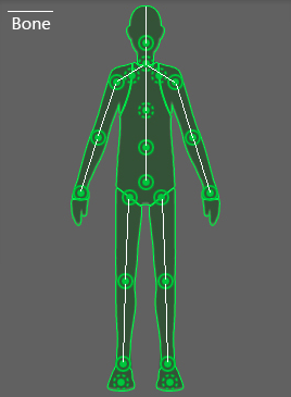
Look at the Scene window and turn the window so that the character looks at you. Note the green bones; Unity uses them. Clicking on any of them will select the corresponding bone in both the Hierarchy and the Inspector .
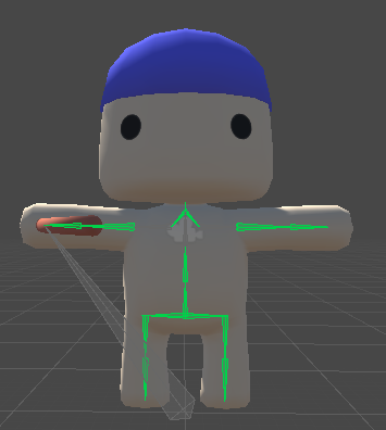
Using the Unity engine of bones resembles the work of the puppeteer. Instead of directly using the animation files to update the bones in each frame, it reads the values and applies them to each humanoid based on its Avatar definition. This provides flexibility when working with different body shapes. Take for example the character with whom we worked - its proportions are unrealistic, but it does not matter, because its skeleton has the necessary bones: the spine, arms, legs, etc. Some of the bones may be shorter than most people, but they are still present.
Now look at the Inspector: you see the figure of a man with green and gray circles scattered over it. All solid circles are necessary for the operation of the Avatar system. If any of them are missing, they turn red and you will not be able to animate the character correctly.
Dotted circles are additional bones for more complex rigs. All gray parts are missing, but optional. For example, our character has no fingers.
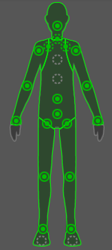
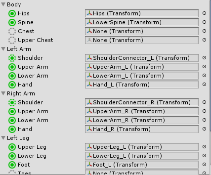
Below is a complete description of the bones, and it is here that you need to link the body parts with the bones. If one of the circles is red, then you need to assign (or reassign) the bone. The skeleton created by us fully met the requirements already when imported into Unity, so no settings are required. Hooray!
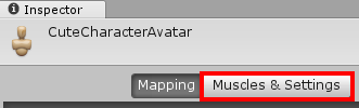
Click the Apply button in the lower right corner and click the Muscles & Settings button at the top of the Inspector. This will allow you to view and tweak the virtual muscles.
You will see three sections:
- Muscle Group Preview
- Per-Muscle Settings
- Additional Settings
In the first, there are several sliders that can be moved left and right to check the correctness of the muscle binding. Experiment with them and see what they do. Note that the muscles of the fingers are not counted, because the character has no fingers. After each test, press the Reset All button to reset all sliders previews.
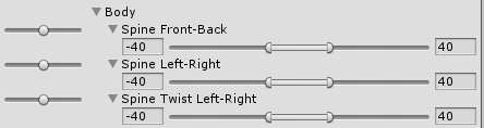
The Per-Muscle Settings section contains sub-sections that can be expanded by clicking on the arrows. In each of them there are separate previews. These subsections allow you to specify minimum and maximum angles to avoid overlaps in your model.
Expand the Left Arm section and try dragging the Arm Down-Up slider . Notice what happens at the minimum value:
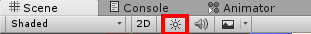
Note: if the character is too dark to create a silhouette, you can turn off the scene lighting in the Scene window by clicking on the small sun icon at the top.
The hand moves through the body of the character. Poorly!
To fix this, move the slider preview to the smallest value and change the minimum angle of the Arm Down-Up section to -20 .

Do the same for Right Arm > Arm Down-Up .

At this point we finish tuning the muscles. Other muscles can be tuned to prevent overlap, but in this tutorial we will focus on moving the arms up and down.
Click the Apply button in the lower right corner to save the images to Avatar and click Done to close the binding mode.

Now it's time to add a character to the scene and give it a playable animation.
Character use
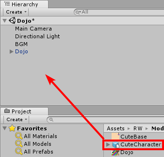
To add a character, drag the CuteCharacter model from the Models folder to the Hierarchy .
Ask the CuteCharacter to rotate (X: 0, Y: 180, Z: 0) to look at the camera.
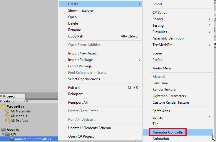
Create a new animation controller by right-clicking on the RW \ Animation Controllers folder and selecting Create> Animation Controller .
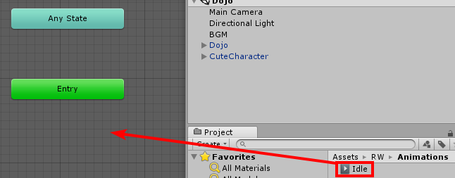
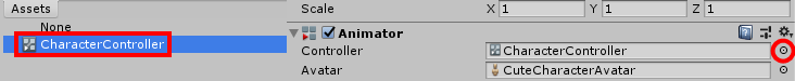
Name it CharacterController and double click on it to open the Animator window. Now drag the Idle animation from the RW \ Animations folder onto the Animator grid to make it the default animation.
Next, select CuteCharacter in the Hierarchy and click on the selector button next to the Controller field . Select CharacterController in the selection window .
Finally, expand the CuteCharacter in the Hierarchy and drag the Cylinder onto Hand_R to make it a child. This is the limitation of adding a separate object, which I mentioned above. If this is not done, the weapon will simply float around the character.

That's all! Click on the Play button to see the character in action.
Now press the Play button again to stop the scene and press CTRL + S to save the changes.
Where to go next?
Congratulations, you have completed the tutorial. The finished project can be downloaded from here .
In this tutorial, you learned the following:
- Create the armature (skeleton) of the character and perform its rigging
- Modify character with accessories and objects
- Export to FBX
- Import Blender Models
- Create and customize a humanoid avatar
- Attach objects to character
- Animate a humanoid in Unity
To use the knowledge gained, you can create several accessories yourself and give them different colors or a palette. If you know the modeling, you can create a character from scratch and rig it.
To learn more about Blender, study the following tutorials:
To learn more about Mecanim and Avatar, read this Unity developer post .