Budget UHF RFID reader and its development
Hello, respectable ladies and gentlemen.
The cheapest UHF RFID reader or EPC Gen2 reader costs retail no less than 200 USD.

How to make a workable UHF RFID reader from parts for 10 USD, and how one could benefit from it, is described below.
Most modern EPC Gen2 RFID readers use specialized chips. They are produced by Impinj, AMS and Phychips. The cheapest chips cost about 20 USD in batches of 1000 pieces. RFID readers turn out wonderful: powerful, nimble and long-range - but expensive.
This spring, an article appeared on the Internet called " Simple Low Cost UHF RFID Reader"about how to assemble a valid RFID reader from common radio components worth about 5 USD in retail. The idea seems to be simple, but only recently came to implementation. The premise for the development is based on the fact that very often a couple of three should be considered slowly near the antenna tags, and paying a lot of money for a reader with a rate of 200-500 tags per second is useless. The reader circuit block is shown in the picture.

Its charm is simplicity. The basis is a conventional microcontroller that generates EPC standard signals on the GPIO leg Gen2, necessary for polling tags.The signals are transmitted to the Melexis TH72035 transmitter chip, then to the antenna via the Johanson 0910CF15B0100 coupler (coupler) The receiver is assembled on one MAX931 comparator according to the following scheme.
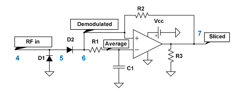
Logic signals from the receiver go to the other GPIO pin of the microprocessor. We get a simple software UHF RFID reader. Of course, writing a soft EPC Gen2 RFID reader is not a pound of raisins. But if you clearly define your goals and use only the right subset of the EPC Gen2 protocol, then the task is greatly simplified.
The authors of the described project consider one of the goals of its further development to be the placement of all RFID reader components on one board. But wouldn’t it be more interesting to go in the opposite direction? That is, to divide the reader into physically separate functional modules and then build an RFID reader with the necessary characteristics from different modules. Everything below is just an idea, without a detailed study.
It is clear that the main module is microprocessor-based. Probably, you need to make it on the Cortex-M0, output it to the UART and USB connectors in order to control the reader. To connect the transceiver module, use a 6-pin connector: Rx, Tx, 2 to power the transceiver, 2 GPIO. Such connectors can be made 2-4, as far as the microprocessor leads are enough.
The transceiver module will be connected to the microprocessor module directly or via a short cable. Perhaps you need to make several options for the transceiver modules with different power and price, but the same connector. The 5th pin of the connector can be used to turn on the transceiver, and the 6th can be used for some kind of sensor if necessary. It makes sense to make a printed circuit board of a transceiver with metallized end half-openings. Then it can be soldered to printed circuit boards with different antennas or a printed circuit board with a coaxial SMA connector.
So, by connecting the microprocessor module and the transceiver module, we get an RFID reader. But just for the sake of this it is not worth fencing the garden. Let's go further. We will insert a board with an RS422 driver and an RJ45 socket into a 6-pin microprocessor module instead of a transceiver (pair 1 - receive, couple 2 - transmit, 3 - power, 4 - GPIO). We’ll stick the same in the transceiver. It is clear that now you can connect the microprocessor module and the transceiver using any patch cord or use an office SCS to connect. In general, the antenna from the microprocessor module can be located very far away. And no coax.
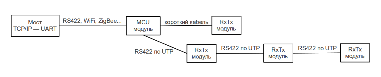
Well, that's not all :) RS422 is a bus. The transceiver can accommodate a D-trigger chip. Connect transceiver modules in series with patch cords. True, you need a second RJ45 connector or a T-splitter, if instead of a D-trigger put a synchronous counter. Using two GPIOs in the fourth pair of UTP, you can select the desired transceiver. It turns out a distributed RFID reader, as in the picture.
Why USB is needed: in order to be able to connect the reader to an Android tablet.
The solution is applicable where you do not need a high speed for reading tags and range.
1. Not suitable for grocery stores. These are RFID stores of the future. And RFID stores of the present are department stores (shoes and clothes). There, RFID readers are already used in fitting rooms (together in an interactive display), at cash desks and smart shelves with goods.
2. Warehouses with Euro pallets (a chain of transceiver modules where the left corners of the pallets are located).
3. Access system for various public events.
4. Surely somewhere else.
Your opinion?
The cheapest UHF RFID reader or EPC Gen2 reader costs retail no less than 200 USD.
How to make a workable UHF RFID reader from parts for 10 USD, and how one could benefit from it, is described below.
Most modern EPC Gen2 RFID readers use specialized chips. They are produced by Impinj, AMS and Phychips. The cheapest chips cost about 20 USD in batches of 1000 pieces. RFID readers turn out wonderful: powerful, nimble and long-range - but expensive.
This spring, an article appeared on the Internet called " Simple Low Cost UHF RFID Reader"about how to assemble a valid RFID reader from common radio components worth about 5 USD in retail. The idea seems to be simple, but only recently came to implementation. The premise for the development is based on the fact that very often a couple of three should be considered slowly near the antenna tags, and paying a lot of money for a reader with a rate of 200-500 tags per second is useless. The reader circuit block is shown in the picture.
Its charm is simplicity. The basis is a conventional microcontroller that generates EPC standard signals on the GPIO leg Gen2, necessary for polling tags.The signals are transmitted to the Melexis TH72035 transmitter chip, then to the antenna via the Johanson 0910CF15B0100 coupler (coupler) The receiver is assembled on one MAX931 comparator according to the following scheme.
Logic signals from the receiver go to the other GPIO pin of the microprocessor. We get a simple software UHF RFID reader. Of course, writing a soft EPC Gen2 RFID reader is not a pound of raisins. But if you clearly define your goals and use only the right subset of the EPC Gen2 protocol, then the task is greatly simplified.
The authors of the described project consider one of the goals of its further development to be the placement of all RFID reader components on one board. But wouldn’t it be more interesting to go in the opposite direction? That is, to divide the reader into physically separate functional modules and then build an RFID reader with the necessary characteristics from different modules. Everything below is just an idea, without a detailed study.
It is clear that the main module is microprocessor-based. Probably, you need to make it on the Cortex-M0, output it to the UART and USB connectors in order to control the reader. To connect the transceiver module, use a 6-pin connector: Rx, Tx, 2 to power the transceiver, 2 GPIO. Such connectors can be made 2-4, as far as the microprocessor leads are enough.
The transceiver module will be connected to the microprocessor module directly or via a short cable. Perhaps you need to make several options for the transceiver modules with different power and price, but the same connector. The 5th pin of the connector can be used to turn on the transceiver, and the 6th can be used for some kind of sensor if necessary. It makes sense to make a printed circuit board of a transceiver with metallized end half-openings. Then it can be soldered to printed circuit boards with different antennas or a printed circuit board with a coaxial SMA connector.
So, by connecting the microprocessor module and the transceiver module, we get an RFID reader. But just for the sake of this it is not worth fencing the garden. Let's go further. We will insert a board with an RS422 driver and an RJ45 socket into a 6-pin microprocessor module instead of a transceiver (pair 1 - receive, couple 2 - transmit, 3 - power, 4 - GPIO). We’ll stick the same in the transceiver. It is clear that now you can connect the microprocessor module and the transceiver using any patch cord or use an office SCS to connect. In general, the antenna from the microprocessor module can be located very far away. And no coax.
Well, that's not all :) RS422 is a bus. The transceiver can accommodate a D-trigger chip. Connect transceiver modules in series with patch cords. True, you need a second RJ45 connector or a T-splitter, if instead of a D-trigger put a synchronous counter. Using two GPIOs in the fourth pair of UTP, you can select the desired transceiver. It turns out a distributed RFID reader, as in the picture.
Why USB is needed: in order to be able to connect the reader to an Android tablet.
The solution is applicable where you do not need a high speed for reading tags and range.
1. Not suitable for grocery stores. These are RFID stores of the future. And RFID stores of the present are department stores (shoes and clothes). There, RFID readers are already used in fitting rooms (together in an interactive display), at cash desks and smart shelves with goods.
2. Warehouses with Euro pallets (a chain of transceiver modules where the left corners of the pallets are located).
3. Access system for various public events.
4. Surely somewhere else.
Your opinion?