November 17, 2012 at 05:49
Simple watch on MSP430
Having read a huge number of articles about Arduino / LaunchPad, I wanted to buy a similar toy. The choice fell on the MSP430, as its price is much more attractive for launching into the world of microcontrollers.
After the painful 5 days of waiting, the magic box was in my hands. After playing for about 10 minutes with LEDs, I wanted to do something more interesting ... For example, a watch!

At hand was an old Siemens A65, who became a donor for my small project. We take out the screen from it and think how to connect it. After a short googling, I successfully ended up on the RadioCot forum threadwhere pinouts and initialization of screens were discussed. If anyone is faced with the task of connecting screens to the microcontroller, then he knows that it is not enough to know the connection diagram, since there is a controller in the screen, for communication with which you need to know the commands. For example, to turn on the screen and display garbage from memory, some controllers need to send several dozen commands, and some need less than 10. So, often datasheets cannot be found on the controllers, and in this case only reading the initialization of the screen during its operation on the phone helps . But I was lucky that the initialization and commands for my screen (in my case LPH8731-3C with the EPSON S1D15G14 controller) were not only dismantled, but I even found a datasheet on it.
And so, we look at the pinout, solder the wiring and connect to the microcontroller.
Now we need to figure out how to communicate with the controller. There are 2 types of received data for the screen controller - command or data. A separate pin is used to select a data type. Otherwise, the data transfer procedure is the same.
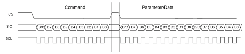
The procedure for transmitting data to the controller, taken from the datasheet. For some reason, the status of the RS / CD pin is not indicated here. By the way, if during the data transfer the CS status changes to Low -> High, the data reception will stop. But at the end of the data transfer, pulling the CS up is not necessary (but recommended).
Now we know how to send data to the controller (well, or at least have an idea). Fortunately, in the datasheet not only all the commands are described, but there is even an example of the initial initialization of the screen. In general, it can be divided into 3 stages: do a controller reset (hardware & software reset), set the initial settings, turn on the display.
Turning on the display, we will see either trash or a white / black screen. That's because the controller changes the state of the matrix relative to the internal memory, and turning it on, it will display everything that it “remembers”. To display any information (or change it), it is enough to change the memory and the controller will update the display (it updates the display constantly with a certain frequency set in the initial setting, the default update frequency is 85Hz). For example, to change the color of a pixel, you just need to write the new value into memory. But first you need to specify the address where to write the new value. If the computer simply sets the address of the memory cell and writes a new value, then you need to specify the memory range to which you can send data sequentially.
For example, to fill the entire screen, you need to select the beginning of the recorded area (x0, y0) and the end (x101, y80). And if you need to change the color of only one pixel, then we respectively set the area [x, y] [x + 1, y + 1].
Having selected the area, we can now simply send data and they will be sequentially written to memory (and how (from left to right, from top to bottom or vice versa) will depend on the initial setting). For example, selecting a 40x40px region, we will need to send successively 1600 values (though this is not entirely true, but more on that in order), which will be stored in memory and this region will be completely updated. And if you continue to send values, the update will continue from the next pixel (in this case, from the first).
We have already figured out how to turn on the display and even how to choose the area for drawing, but how do I send the color? The display can work with 2 color palettes:
In the case of 8-bit color, everything is simple - just send 8 bits for each color (namely, R2R1R0G2G1G0B1B0, where R2R1R0 is 3 bits of red color, etc. 3 bits for red and green, and 2 bits for blue).
But in the case of 12-bit color, everything is a little more complicated. There are already 4 bits for each shade. I will give a picture from a datasheet.
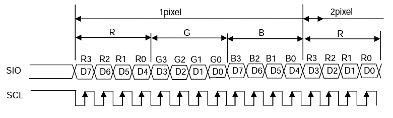
As you can see, one and a half bytes are used to send one color. If you need to change only 1 pixel, then 2 bytes of information are sent, where in the second byte D3-D0 will not be used. And if you need to change 2 pixels, then just send 3 bytes (where D3-D0 of the second byte will be the beginning, and D7-D0 of the third byte will be the continuation of the color for the second pixel).
And now the hardest part is to draw a watch. As you can see, they are stylized as a segment indicator, so to display the clock just draw 2 types of segments (vertical and horizontal) in different places.
First you need to decide on the design. Thanks to the great program from MS - Paint, it really helped me with this;).

That's what I did. Each segment is 12x4px in size (and vertical, respectively, on the contrary - 4x12px).
And now let's remember about the choice of area for drawing. You can also specify a 12x4 area in the right place and draw a segment without redrawing the entire screen. If you take a closer look at the segment, you will notice that it is almost completely filled with one color, except for the corners. So the algorithm for drawing a segment is quite simple: we start filling the memory with an empty color (unfortunately there is no transparency, so we fill it with the background color), add checks for the upper right and lower left corners, and fill the last pixel with the background color too. Likewise for vertical ones. And how to draw dots, I won’t even tell :).
Now you need to turn the number into a set of segments (for example, to display 1, you need to draw only the right vertical segments). I decided this quite simply - I created an array of segment values for various digits (from 0 to 9). Substituting a digit into it, I get an array with 1/0 values that controlled the rendering of segments. For example, 1 means that the segment needs to be drawn, and 0 means that it is not necessary (or draw it “inactive”). And knowing what and where to draw, to make a function is not difficult.
And so we come to the end of the article. I hope I was able to explain the principle of their work in as much detail as possible :) And for a snack a short video on how they work and blink “dots”.

PS
Perhaps spelling, grammar and punctuation errors are present in this article. If you find them, I kindly ask you to send me a message in PM, and not write a comment.
The article does not write about the implementation of watches as such because they are not completed :) Initially, it was planned to make a small gadget where the display, external flash memory and external clock-calendar would be used, but since I accidentally bought the wrong watch, everything got up :) Another reason - I wanted to use a larger display, but could not buy a suitable one, for example, from the Chinese Nokla n95 8gb. Can someone tell me where to buy one?
If someone needs the source code - contact, I can share :) If anyone has questions about the implementation of the output of characters on the screen (print text) - I can also share the source code (I did not write about it, here seems to be an article about the clock: ), and also does not pull on a separate post). I can also share the library for working with the screen from Siemens CX75 (on the SSD-1286 controller, there is even a datasheet), I wrote for myself, but accidentally burned it.
After the painful 5 days of waiting, the magic box was in my hands. After playing for about 10 minutes with LEDs, I wanted to do something more interesting ... For example, a watch!
At hand was an old Siemens A65, who became a donor for my small project. We take out the screen from it and think how to connect it. After a short googling, I successfully ended up on the RadioCot forum threadwhere pinouts and initialization of screens were discussed. If anyone is faced with the task of connecting screens to the microcontroller, then he knows that it is not enough to know the connection diagram, since there is a controller in the screen, for communication with which you need to know the commands. For example, to turn on the screen and display garbage from memory, some controllers need to send several dozen commands, and some need less than 10. So, often datasheets cannot be found on the controllers, and in this case only reading the initialization of the screen during its operation on the phone helps . But I was lucky that the initialization and commands for my screen (in my case LPH8731-3C with the EPSON S1D15G14 controller) were not only dismantled, but I even found a datasheet on it.
And so, we look at the pinout, solder the wiring and connect to the microcontroller.
Pinout for LPH8731-3C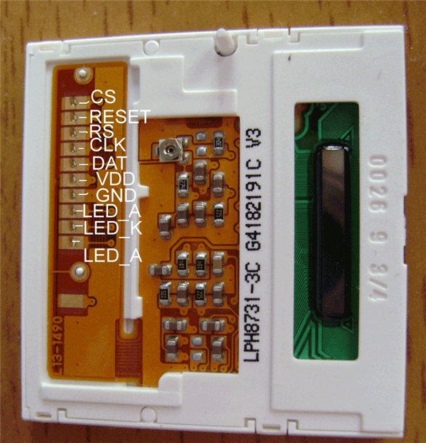
Pinout for LPH8731-3C. (Taken from the RadioKot forum )
Where:
By the way, some might already notice that SPI is used here for data transfer, so that CLK and DAT can be connected to the MSP430 SPI pins.
Pinout for LPH8731-3C. (Taken from the RadioKot forum )
Where:
- CS - Chip Select. When in the Low state, the chip is ready to receive information.
- RESET - foot for resetting the controller. The reset signal is the transition from High -> Low -> High (according to the specification of the controller, the minimum time is 5ms).
- RS - Serves to determine the type of data being transferred (in the datasheet and it is designated as CD in me). To send a command, it must be in the Low state, to transmit data - High.
- CLK - serves as a clock signal for data transmission.
- DAT - for data transfer.
- VDD - according to the specification from + 1.6V to + 3.6V.
- GND - I hope you can guess for yourself?;)
- LED_A - both connectors for supplying power to the backlight. Here it is better to give voltage through the resistor (you can without it, but in my case one of the LEDs began to overheat, which resulted in a light on the screen).
- LED_K is for GND.
By the way, some might already notice that SPI is used here for data transfer, so that CLK and DAT can be connected to the MSP430 SPI pins.
We get a "barrel organ"
Now we need to figure out how to communicate with the controller. There are 2 types of received data for the screen controller - command or data. A separate pin is used to select a data type. Otherwise, the data transfer procedure is the same.
The procedure for transmitting data to the controller, taken from the datasheet. For some reason, the status of the RS / CD pin is not indicated here. By the way, if during the data transfer the CS status changes to Low -> High, the data reception will stop. But at the end of the data transfer, pulling the CS up is not necessary (but recommended).
Bit of evil code
The code is for CSS (TI's Code Composer Studio).
Here it is not completely, but only pieces for example. Comments in English, as I like it better :)
LPH87313C.h
LPH87313C.s
Here it is not completely, but only pieces for example. Comments in English, as I like it better :)
LPH87313C.h
/**********************************************************/
/*		Pins and outputs								  */
/**********************************************************/
// Chip Select line		pin1.0
#define LCD_CS BIT7
#define LCD_CS_DIR P1DIR
#define LCD_CS_OUT P1OUT
// Hardware Reset		pin1.1
#define LCD_RESET BIT6
#define LCD_RESET_DIR P1DIR
#define LCD_RESET_OUT P1OUT
// Command/Data mode line	pin1.4
#define LCD_CD BIT3
#define LCD_CD_DIR P1DIR
#define LCD_CD_OUT P1OUT
// SPI
#define SPI UCA0TXBUF
LPH87313C.s
void LCD_SendCmd(unsigned char Cmd)
{
	LCD_CS_OUT |= LCD_CS; // set CS pin to High
	LCD_CD_OUT &= ~LCD_CD; // set CD pin to Low
	LCD_CS_OUT &= ~LCD_CS;
	SPI = Cmd;
}
void LCD_SendDat(unsigned char Data)
{
	LCD_CD_OUT |= LCD_CD; // set CD pin to High
	SPI = Data;
}
Now we know how to send data to the controller (well, or at least have an idea). Fortunately, in the datasheet not only all the commands are described, but there is even an example of the initial initialization of the screen. In general, it can be divided into 3 stages: do a controller reset (hardware & software reset), set the initial settings, turn on the display.
And here are a lot of commands to send
In principle, most parameters are set as is, but some things can be changed. For example, in what order the values will be written to the memory (from top to bottom - from right to left / from bottom to top - from right to left / etc.), contrast, as well as color depth (256 colors or 4096).
LPH87313C.s
LPH87313C.s
void LCD_Init()
{
	// Set pins to output direction
	LCD_CS_DIR |= LCD_CS;
	LCD_RESET_DIR |= LCD_RESET;
	LCD_CD_DIR |= LCD_CD;
	LCD_CS_OUT &= ~LCD_CS;
	LCD_RESET_OUT &= ~LCD_RESET;
	LCD_CD_OUT &= ~LCD_CD;
	__delay_cycles(160000); //wait 100ms (F_CPU 16MHz)
	LCD_RESET_OUT |= LCD_RESET;
	__delay_cycles(160000);
	LCD_SendCmd(0x01); //reset sw
	__delay_cycles(80000);
	LCD_SendCmd(0xc6); //initial escape
	LCD_SendCmd(0xb9); //Refresh set
	LCD_SendDat(0x00);
	__delay_cycles(160000);
	LCD_SendCmd(0xb6); //Display control
	LCD_SendDat(0x80); //
	LCD_SendDat(0x04); //
	LCD_SendDat(0x0a); //
	LCD_SendDat(0x54); //
	LCD_SendDat(0x45); //
	LCD_SendDat(0x52); //
	LCD_SendDat(0x43); //
	LCD_SendCmd(0xb3); //Gray scale position set 0
	LCD_SendDat(0x02); //
	LCD_SendDat(0x0a); //
	LCD_SendDat(0x15); //
	LCD_SendDat(0x1f); //
	LCD_SendDat(0x28); //
	LCD_SendDat(0x30); //
	LCD_SendDat(0x37); //
	LCD_SendDat(0x3f); //
	LCD_SendDat(0x47); //
	LCD_SendDat(0x4c); //
	LCD_SendDat(0x54); //
	LCD_SendDat(0x65); //
	LCD_SendDat(0x75); //
	LCD_SendDat(0x80); //
	LCD_SendDat(0x85); //
	LCD_SendCmd(0xb5); //Gamma curve
	LCD_SendDat(0x01); //
	LCD_SendCmd(0xbd); //Common driver output select
	LCD_SendDat(0x00); //
	LCD_SendCmd(0xbe); //Power control
	LCD_SendDat(0x54); //0x58 before
	LCD_SendCmd(0x11); //sleep out
	__delay_cycles(800000);
	LCD_SendCmd(0xba); //Voltage control
	LCD_SendDat(0x2f); //
	LCD_SendDat(0x03); //
	LCD_SendCmd(0x25); //Write contrast
	LCD_SendDat(0x60); //
	LCD_SendCmd(0xb7); //Temperature gradient
	LCD_SendDat(0x00); //
	LCD_SendDat(0x00); //
	LCD_SendDat(0x00); //
	LCD_SendDat(0x00); //
	LCD_SendDat(0x00); //
	LCD_SendDat(0x00); //
	LCD_SendDat(0x00); //
	LCD_SendDat(0x00); //
	LCD_SendDat(0x00); //
	LCD_SendDat(0x00); //
	LCD_SendDat(0x00); //
	LCD_SendDat(0x00); //
	LCD_SendDat(0x00); //
	LCD_SendDat(0x00); //
	LCD_SendCmd(0x03); //Booster voltage ON
	__delay_cycles(800000);
	LCD_SendCmd(0x36); //Memory access control
	LCD_SendDat(0x48); //
	LCD_SendCmd(0x2d); //Color set
	LCD_SendDat(0x00); //
	LCD_SendDat(0x03); //
	LCD_SendDat(0x05); //
	LCD_SendDat(0x07); //
	LCD_SendDat(0x09); //
	LCD_SendDat(0x0b); //
	LCD_SendDat(0x0d); //
	LCD_SendDat(0x0f); //
	LCD_SendDat(0x00); //
	LCD_SendDat(0x03); //
	LCD_SendDat(0x05); //
	LCD_SendDat(0x07); //
	LCD_SendDat(0x09); //
	LCD_SendDat(0x0b); //
	LCD_SendDat(0x0d); //
	LCD_SendDat(0x0f); //
	LCD_SendDat(0x00); //
	LCD_SendDat(0x05); //
	LCD_SendDat(0x0b); //
	LCD_SendDat(0x0f); //
	LCD_SendCmd(0x3a); //interface pixel format
	LCD_SendDat(0x03); // 0x02 for 8-bit 0x03 for 12bit
	__delay_cycles(1600000);
	LCD_SendCmd(0x29); //Display ON
}
Our address is not a house or a street, our address is ...
Turning on the display, we will see either trash or a white / black screen. That's because the controller changes the state of the matrix relative to the internal memory, and turning it on, it will display everything that it “remembers”. To display any information (or change it), it is enough to change the memory and the controller will update the display (it updates the display constantly with a certain frequency set in the initial setting, the default update frequency is 85Hz). For example, to change the color of a pixel, you just need to write the new value into memory. But first you need to specify the address where to write the new value. If the computer simply sets the address of the memory cell and writes a new value, then you need to specify the memory range to which you can send data sequentially.
For example, to fill the entire screen, you need to select the beginning of the recorded area (x0, y0) and the end (x101, y80). And if you need to change the color of only one pixel, then we respectively set the area [x, y] [x + 1, y + 1].
Having selected the area, we can now simply send data and they will be sequentially written to memory (and how (from left to right, from top to bottom or vice versa) will depend on the initial setting). For example, selecting a 40x40px region, we will need to send successively 1600 values (though this is not entirely true, but more on that in order), which will be stored in memory and this region will be completely updated. And if you continue to send values, the update will continue from the next pixel (in this case, from the first).
Commands for specifying an area
LCD_SendCmd(0x2A); //задаем область по X (x0 - начальный, x1 - конечный)
LCD_SendDat(x0);
LCD_SendDat(x1);
LCD_SendCmd(0x2B); //задаем область по Y (y0 - начальный, y1 - конечный)
LCD_SendDat(y0+1); //у этого контроллера Y отсчитывается от 1, а не 0
LCD_SendDat(y1+1);
LCD_SendCmd(0x2C); // отправляем команду на начало записи в память и начинаем посылать данные
Letter for you! True in Chinese ...
We have already figured out how to turn on the display and even how to choose the area for drawing, but how do I send the color? The display can work with 2 color palettes:
- 8bit (256 colors)
- 12bit (4096 colors)
In the case of 8-bit color, everything is simple - just send 8 bits for each color (namely, R2R1R0G2G1G0B1B0, where R2R1R0 is 3 bits of red color, etc. 3 bits for red and green, and 2 bits for blue).
But in the case of 12-bit color, everything is a little more complicated. There are already 4 bits for each shade. I will give a picture from a datasheet.
As you can see, one and a half bytes are used to send one color. If you need to change only 1 pixel, then 2 bytes of information are sent, where in the second byte D3-D0 will not be used. And if you need to change 2 pixels, then just send 3 bytes (where D3-D0 of the second byte will be the beginning, and D7-D0 of the third byte will be the continuation of the color for the second pixel).
Again a portion of code
An example of the fill function of the entire screen.
void LCD_Flush(unsigned char R, unsigned char G, unsigned char B)
{
	volatile int i = 4040;
	volatile char B0, B1, B2;
	B0 = ((R << 4) & 0xF0) + (G & 0x0F);
	B1 = ((B << 4) & 0xF0) + (R & 0x0F);
	B2 = ((G << 4) & 0xF0) + (B & 0x0F);
	LCD_SendCmd(0x2A);
	LCD_SendDat(0);
	LCD_SendDat(100);
	LCD_SendCmd(0x2B);
	LCD_SendDat(1);
	LCD_SendDat(80);
	LCD_SendCmd(0x2C);
	while (i--)
	{
		LCD_CD_OUT |= LCD_CD;
		SPI = B0;
		SPI = B1;
		SPI = B2;
	}
}
Where is the promised watch?
And now the hardest part is to draw a watch. As you can see, they are stylized as a segment indicator, so to display the clock just draw 2 types of segments (vertical and horizontal) in different places.
First you need to decide on the design. Thanks to the great program from MS - Paint, it really helped me with this;).
That's what I did. Each segment is 12x4px in size (and vertical, respectively, on the contrary - 4x12px).
And now let's remember about the choice of area for drawing. You can also specify a 12x4 area in the right place and draw a segment without redrawing the entire screen. If you take a closer look at the segment, you will notice that it is almost completely filled with one color, except for the corners. So the algorithm for drawing a segment is quite simple: we start filling the memory with an empty color (unfortunately there is no transparency, so we fill it with the background color), add checks for the upper right and lower left corners, and fill the last pixel with the background color too. Likewise for vertical ones. And how to draw dots, I won’t even tell :).
A set of obscene words in an incomprehensible language
Example function for displaying a horizontal segment. greenBright is the “bright” color constant (for the active segment), greenDim is the color constant for the inactive segment. BG0, BG1, BG2 - bit constants for sketching the background.
And if you notice __delay_cycles - this is an inexplicable magic, without which it does not work (although most likely the hardware SPI does not have time to send data, since they are sent not in one clock cycle (but much faster, unlike if you implement sending on your own)).
And if you notice __delay_cycles - this is an inexplicable magic, without which it does not work (although most likely the hardware SPI does not have time to send data, since they are sent not in one clock cycle (but much faster, unlike if you implement sending on your own)).
void drawHorizontal(char type, unsigned char x, unsigned char y)
{
	volatile unsigned char i = 22, B2, B1, B0;
	if (type)
	{
		B0 = greenBright;
		B1 = 0;
		B2 = (greenBright << 4) & 0xF0;
	} else {
		B0 = greenDim;
		B1 = 0;
		B2 = (greenDim << 4) & 0xF0;
	}
	LCD_SendCmd(0x2A);
	LCD_SendDat(x);
	LCD_SendDat(x+11);
	LCD_SendCmd(0x2B);
	LCD_SendDat(y+1);
	LCD_SendDat(y+4);
	LCD_SendCmd(0x2C);
	__delay_cycles(4);
	LCD_CD_OUT |= LCD_CD;
	SPI = BG0;
	SPI = (BG1 << 4) & 0xF0;
	__delay_cycles(2);
	SPI = B2;
	while(i--)
	{
		if (i == 17)
		{
			SPI = B0;
			__delay_cycles(2);
			SPI = (BG0 >> 4) & 0x0F;
			__delay_cycles(2);
			SPI = (BG0 << 4) & 0xF0 + (BG1 << 4) & 0x0F;
			continue;
		}
		if (i == 4)
		{
			SPI = BG0;
			SPI = (BG1 << 4) & 0xF0;
			__delay_cycles(2);
			SPI = B2;
			continue;
		}
		SPI = B0;
		SPI = B1;
		SPI = B2;
	}
	SPI = B0;
	__delay_cycles(2);
	SPI = (BG0 >> 4) & 0x0F;
	__delay_cycles(2);
	SPI = (BG0 << 4) & 0xF0 + (BG1 << 4) & 0x0F;
}
Now you need to turn the number into a set of segments (for example, to display 1, you need to draw only the right vertical segments). I decided this quite simply - I created an array of segment values for various digits (from 0 to 9). Substituting a digit into it, I get an array with 1/0 values that controlled the rendering of segments. For example, 1 means that the segment needs to be drawn, and 0 means that it is not necessary (or draw it “inactive”). And knowing what and where to draw, to make a function is not difficult.
Simple array
/********************************************************************************************
* 	Array for Clock
*  	   	   ____
* 		 _|__1_|_
* 		|6|    |2|
* 		|_|____|_|
* 		 _|__7_|_
* 		|5|    |3|
* 		|_|____|_|
* 		  |__4_|
*
********************************************************************************************/
static const char HH[10][7] = {
		{1,1,1,1,1,1,0}, // 0
		{0,1,1,0,0,0,0}, // 1
		{1,1,0,1,1,0,1}, // 2
		{1,1,1,1,0,0,1}, // 3
		{0,1,1,0,0,1,1}, // 4
		{1,0,1,1,0,1,1}, // 5
		{1,0,1,1,1,1,1}, // 6
		{1,1,1,0,0,0,0}, // 7
		{1,1,1,1,1,1,1}, // 8
		{1,1,1,1,0,1,1}  // 9
};
Clock Drawing Code
void drawClock(char hh, char mm, char dots)
{
	volatile char h0, h1, m0, m1;
	h0 = hh / 10;
	h1 = hh - (h0 * 10);
	m0 = mm / 10;
	m1 = mm - (m0 * 10);
	drawHorizontal(HH[h0][0], 9, 25);
	drawHorizontal(HH[h1][0], 31, 25);
	drawHorizontal(HH[m0][0], 58, 25);
	drawHorizontal(HH[m1][0], 80, 25);
	drawVertical(HH[h0][5], 6, 29);
	drawVertical(HH[h0][1], 20, 29);
	drawVertical(HH[h1][5], 28, 29);
	drawVertical(HH[h1][1], 42, 29);
	drawVertical(HH[m0][5], 55, 29);
	drawVertical(HH[m0][1], 69, 29);
	drawVertical(HH[m1][5], 77, 29);
	drawVertical(HH[m1][1], 91, 29);
	drawHorizontal(HH[h0][6], 9, 38);
	drawHorizontal(HH[h1][6], 31, 38);
	drawHorizontal(HH[m0][6], 58, 38);
	drawHorizontal(HH[m1][6], 80, 38);
	drawVertical(HH[h0][4], 6, 42);
	drawVertical(HH[h0][2], 20, 42);
	drawVertical(HH[h1][4], 28, 42);
	drawVertical(HH[h1][2], 42, 42);
	drawVertical(HH[m0][4], 55, 42);
	drawVertical(HH[m0][2], 69, 42);
	drawVertical(HH[m1][4], 77, 42);
	drawVertical(HH[m1][2], 91, 42);
	drawHorizontal(HH[h0][3], 9, 51);
	drawHorizontal(HH[h1][3], 31, 51);
	drawHorizontal(HH[m0][3], 58, 51);
	drawHorizontal(HH[m1][3], 80, 51);
	drawDots(dots);
}
And so we come to the end of the article. I hope I was able to explain the principle of their work in as much detail as possible :) And for a snack a short video on how they work and blink “dots”.
PS
Perhaps spelling, grammar and punctuation errors are present in this article. If you find them, I kindly ask you to send me a message in PM, and not write a comment.
The article does not write about the implementation of watches as such because they are not completed :) Initially, it was planned to make a small gadget where the display, external flash memory and external clock-calendar would be used, but since I accidentally bought the wrong watch, everything got up :) Another reason - I wanted to use a larger display, but could not buy a suitable one, for example, from the Chinese Nokla n95 8gb. Can someone tell me where to buy one?
If someone needs the source code - contact, I can share :) If anyone has questions about the implementation of the output of characters on the screen (print text) - I can also share the source code (I did not write about it, here seems to be an article about the clock: ), and also does not pull on a separate post). I can also share the library for working with the screen from Siemens CX75 (on the SSD-1286 controller, there is even a datasheet), I wrote for myself, but accidentally burned it.