Creating tracks in the snow in Unreal Engine 4
- Transfer
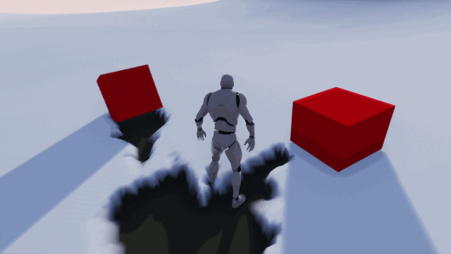
If you are playing modern AAA games, you might notice a tendency to use snow-covered landscapes. For example, they are in Horizon Zero Dawn , Rise of the Tomb Raider and God of War . In all these games, snow has an important feature: you can leave traces on it!
Due to this interaction with the environment, the player is immersed in the game. It makes the environment more realistic, and let's be honest - it's just interesting. Why spend long hours creating a curious mechanic if you can just let a player fall to the ground and make snow angels?
In this tutorial you will learn the following:
- Create traces using scene capture to mask objects close to the ground
- Use a landscape mask to create deformable snow.
- For optimization, display traces in the snow just next to the player.
Note: it is understood that you already know the basics of working with the Unreal Engine. If you are a beginner, then learn our series of Unreal Engine tutorials for beginners .
Getting Started
Download materials for this tutorial. Unzip them, go to SnowDeformationStarter and open SnowDeformation.uproject . In this tutorial, we will create traces using a character and several boxes.
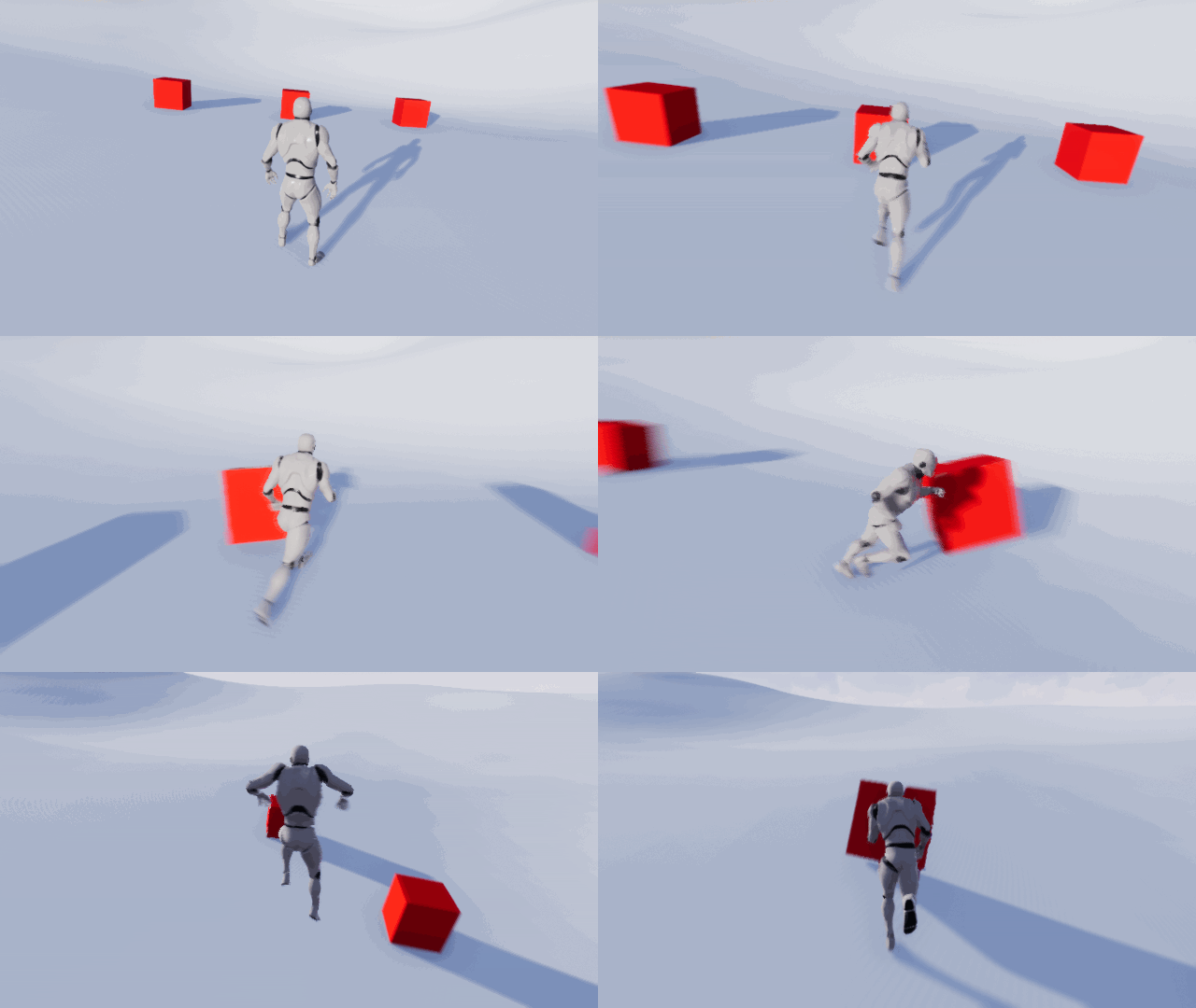
Before we begin, you need to know that the method from this tutorial will only save traces in a given area, and not around the world, because the speed depends on the resolution of the target render.
For example, if we want to store traces for a large area, we will have to increase the resolution. But it also increases the effect of capturing the scene on the speed of the game and the amount of memory under the target render. For optimization it is necessary to limit the scope and resolution.
Having dealt with this, let's find out what is needed to implement the tracks in the snow.
The implementation of traces in the snow
The first thing you need to create traces is the target render . The target render will be a mask in grayscale, in which white indicates the presence of a trace, and black indicates its absence. Then we can project the target render to the ground and use it to blend textures and vertex offset.
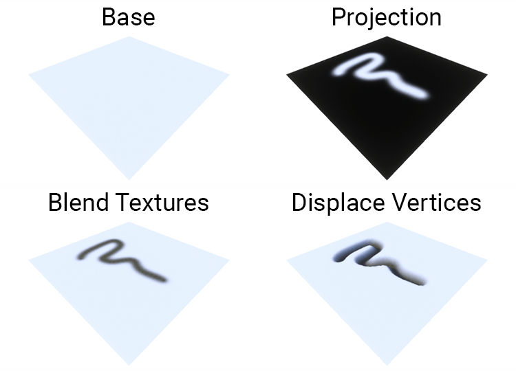
The second thing we need is a way of masking only the objects affecting the snow. This can be accomplished by first rendering objects in Custom Depth . You can then use scene capture with the post process material to mask all objects rendered in Custom Depth. Then you can bring the mask to the target render.
Note: scene capture is essentially a camera with the ability to output the target renderer.
The most important part of capturing the scene - a place of its location. Below is an example of a target render captured from a top view . Here are masked by a third-person character and boxes.
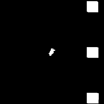
At first glance, the capture from the top view suits us. Forms look like meshes, so there shouldn't be any problems, right?
Not really. The problem of capturing from the top view is that it captures nothing under the widest point. Here is an example:
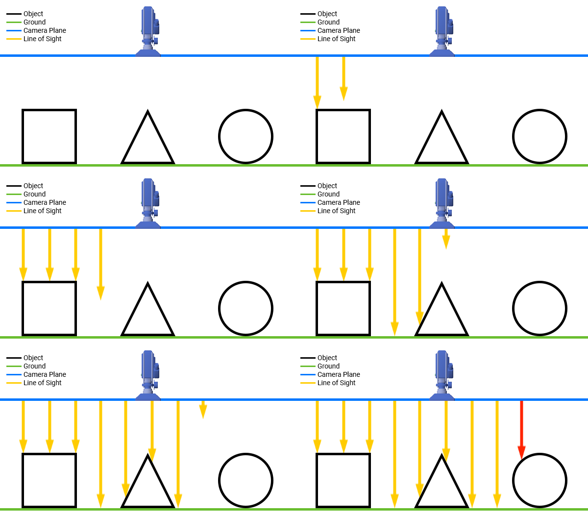
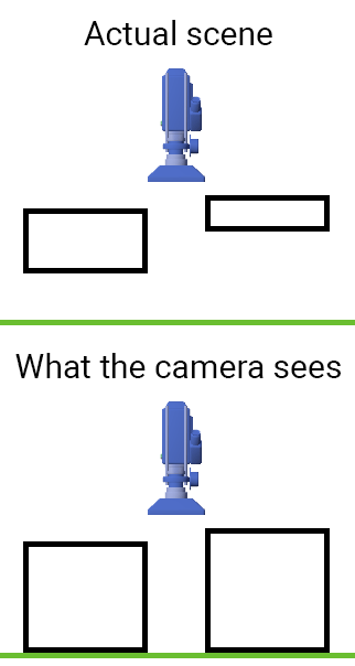
Imagine that the yellow arrows go all the way to the ground. In the case of a cube and a cone, the point of the arrow will always remain inside the object. However, in the case of a sphere, the points coming out of it when approaching the earth. But according to the camera, the point is always inside the sphere. Here is what the sphere will look like for the camera:

Therefore, the sphere mask will be larger than it should, even if the area of contact with the ground is small.
In addition, this problem is complemented by the fact that it is difficult for us to determine whether the object touches the earth.
To cope with both of these problems, you can capture it from below .
Bottom grip
The bottom grip looks like this:
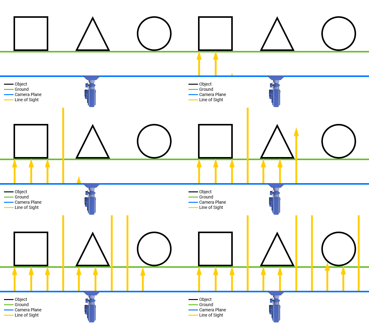
As you can see, the camera now captures the lower side, that is, the one that touches the ground. This eliminates the problem of the “widest area” appearing when seizing from above.
To determine whether an object touches the ground, you can use post-processing material to perform depth checks. It checks to see if the depth of the object is greater than the depth of the earth and below its specified displacement. If both conditions are met, then we can mask this pixel.

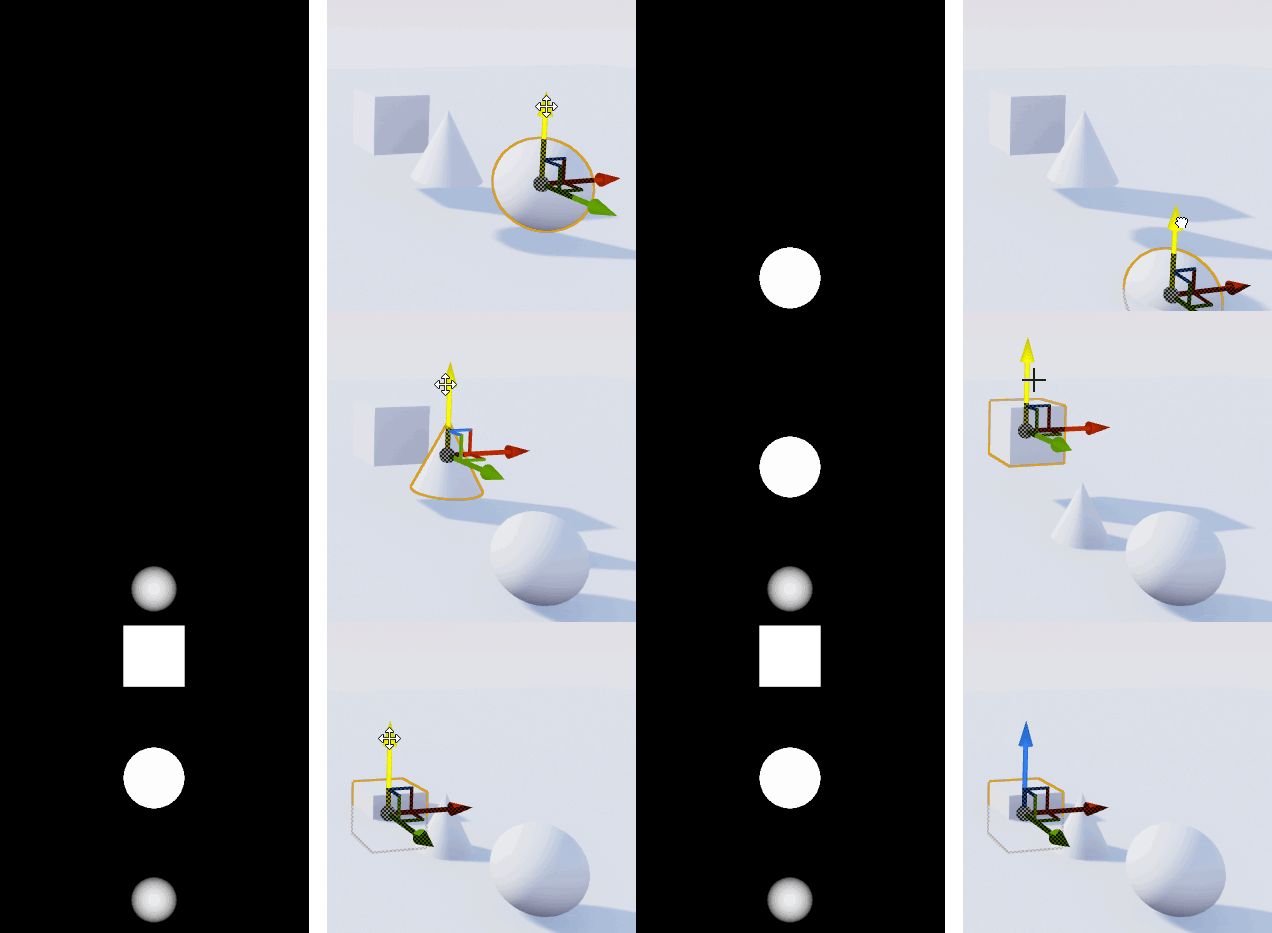
Below is an example inside the engine with a capture zone 20 units above the ground. Notice that a mask appears only when an object passes through a certain point. Also note that the mask becomes whiter as the object approaches the ground.
To begin, create a post-processing material to perform a depth check.
Creating Depth Verification Material
To perform a depth check, you need to use two depth buffers - one for the ground, the other for objects affecting the snow. Since the capture of the scene sees only the ground, the Scene Depth will display the depth for the ground. To get the depth for the objects, we will simply render them with Custom Depth .
Note: to save time, I have already rendered character and boxes in Custom Depth. If you want to add other objects affecting the snow, then you must enable the Render CustomDepth Pass for them .
First, you need to calculate the distance of each pixel to the ground. Open Materials \ PP_DepthCheck and create the following:

Next, you need to create a capture zone. To do this, add the selected nodes:
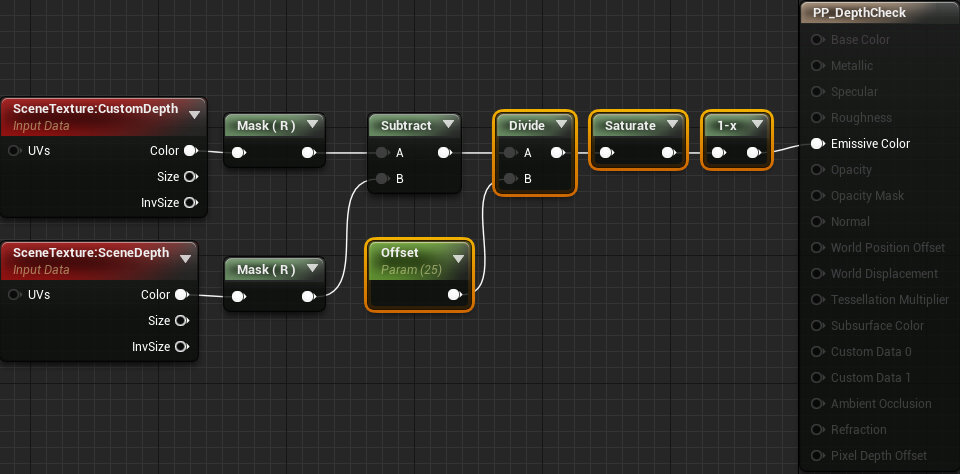
Now, if a pixel is within 25 units of the ground, it will appear in the mask. The brightness of the masking depends on how close the pixel is to the ground. Click on Apply and return to the main editor.
Next you need to create a capture scene.
Creating a scene capture
First, we need a target render, in which we can record the capture of the scene. Navigate to the RenderTargets folder and create a new Render Target called RT_Capture .
Now let's create a capture scene. In this tutorial, we will add a scene capture to the blueprint, because later we will need a script for it. Open Blueprints \ BP_Capture and add Scene Capture Component 2D . Call it SceneCapture .
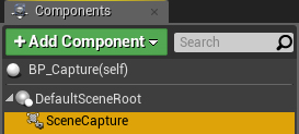
First we need to set the turn of the grip so that it looks at the ground. Go to the Details panel and set the Rotation values (0, 90, 90) .

Next comes the type of projection. Since the mask is a 2D representation of the scene, we need to get rid of perspective distortion. To do this, set the Projection \ Projection Type value to Orthographic .

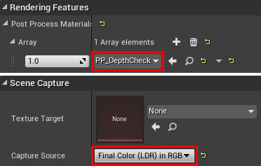
Next, we need to tell the scene capture what target render to write to. To do this, select the RT_Capture value for Scene Capture \ Texture Target .

Finally, we need to use depth checking material. Add to the Rendering Features \ the Post the Process Materials PP_DepthCheck . For the post-processing to work, we also need to change the Scene Capture \ Capture Source to Final Color (LDR) in RGB .
Now that the scene capture is set, we need to specify the size of the capture area.
Set the size of the capture area
Since the target render is better to use low resolutions, we need to use the space effectively. That is, we must choose which area will cover one pixel. For example, if the resolution of the capture area and the target render are the same, then we get a 1: 1 ratio. Each pixel will cover an area of 1 × 1 (in world units).
For tracks on the snow, the 1: 1 ratio is not required, because we would probably not need such detailing. I recommend using larger ratios because it will allow you to increase the size of the capture area at low resolution. But do not make the ratio too large, otherwise the details will be lost. In this tutorial, we will use an 8: 1 ratio, that is, the size of each pixel will be 8 × 8 world units.
You can change the size of the capture area by changing the Scene Capture \ Ortho Width property . For example, if you want to capture an area of 1024 × 1024, set the value to 1024. Since we use an 8: 1 ratio, set the value to 2048 (the resolution resolution of the target render is 256 × 256 by default).
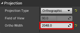
This means that capturing a scene will capture an area of 2048 × 2048 . It is approximately 20 × 20 meters.
The material of the earth also needs access to the size of the grip for proper projection of the target render. The easiest way to do this is to keep the capture size in the Material Parameter Collection . In essence, this is a collection of variables that any material can access .
Capture size preservation
Return to the main editor and go to the Materials folder . Create a Material Parameter Collection that will be in Materials & Textures . Rename it to MPC_Capture and open it.
Then create a new Scalar Parameter and name it CaptureSize . Do not worry about setting its value - we will deal with this in blueprints.

Go back to BP_Capture and add the selected nodes to the Event BeginPlay . Select for Collection value MPC_Capture , and for the Parameter Name value CaptureSize .

Now any material can get the Ortho Width value by reading it from the CaptureSize parameter . So far with the capture of the scene we are finished. Click on Compile and return to the main editor. The next step is to project the target render onto the ground and use it to deform the landscape.
Landscape deformation
Open M_Landscape and go to the Details panel. Then set the following properties:
- For Two Sided, select the value enabled . Since the capture of the scene will “look” from below, he will only see the opposite faces of the earth. By default, the engine does not render back faces of meshes. This means that it will not preserve the depth of the earth in the depth buffer. To fix this, we need to tell the engine to render both sides of the mesh.
- For D3D11 Tessellation, select Flat Tessellation (PN Triangles can also be used). Tessellation will break the triangles of the mesh into smaller ones. In essence, this increases the resolution of the mesh and allows us to obtain finer details when the vertices are shifted. Without this, the density of the vertices will be too small to create plausible traces.
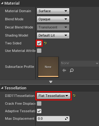
After you turn on the tessellation, World Displacement and Tessellation Multiplier will turn on .

Tessellation Multipler controls the amount of tessellation. In this tutorial we will not connect this node, that is, we use the default value ( 1 ).
World Displacement receives a vector value that describes in which direction and how far to move the vertex. To calculate the value for this contact, we need to first project the target render to the ground.
Projecting target render
To project the target renderer, it is necessary to calculate its UV coordinates. To do this, create the following scheme:

What's going on here:
- First we need to get the position on the XY of the current vertex. Since we are capturing from the bottom, the X coordinate is inverted, so you need to flip it back (if we were capturing from above, we would not need it).
- In this part, two tasks are performed. First, it centers the target render so that its middle is in the coordinates (0, 0) of the world space. It then converts coordinates from world space to UV space.
Next, create the selected nodes and combine the previous calculations as shown below. For Texture Texture Sample, select the RT_Capture value .
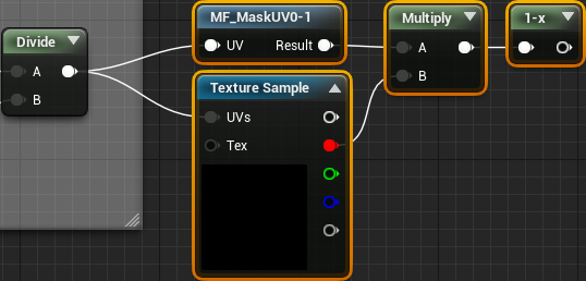
This will project the target render to the ground. However, all vertices outside the capture region will sample the edges of the target render. This is actually a problem, because the target render should only be used for vertices inside the capture area. Here is how it looks in the game:
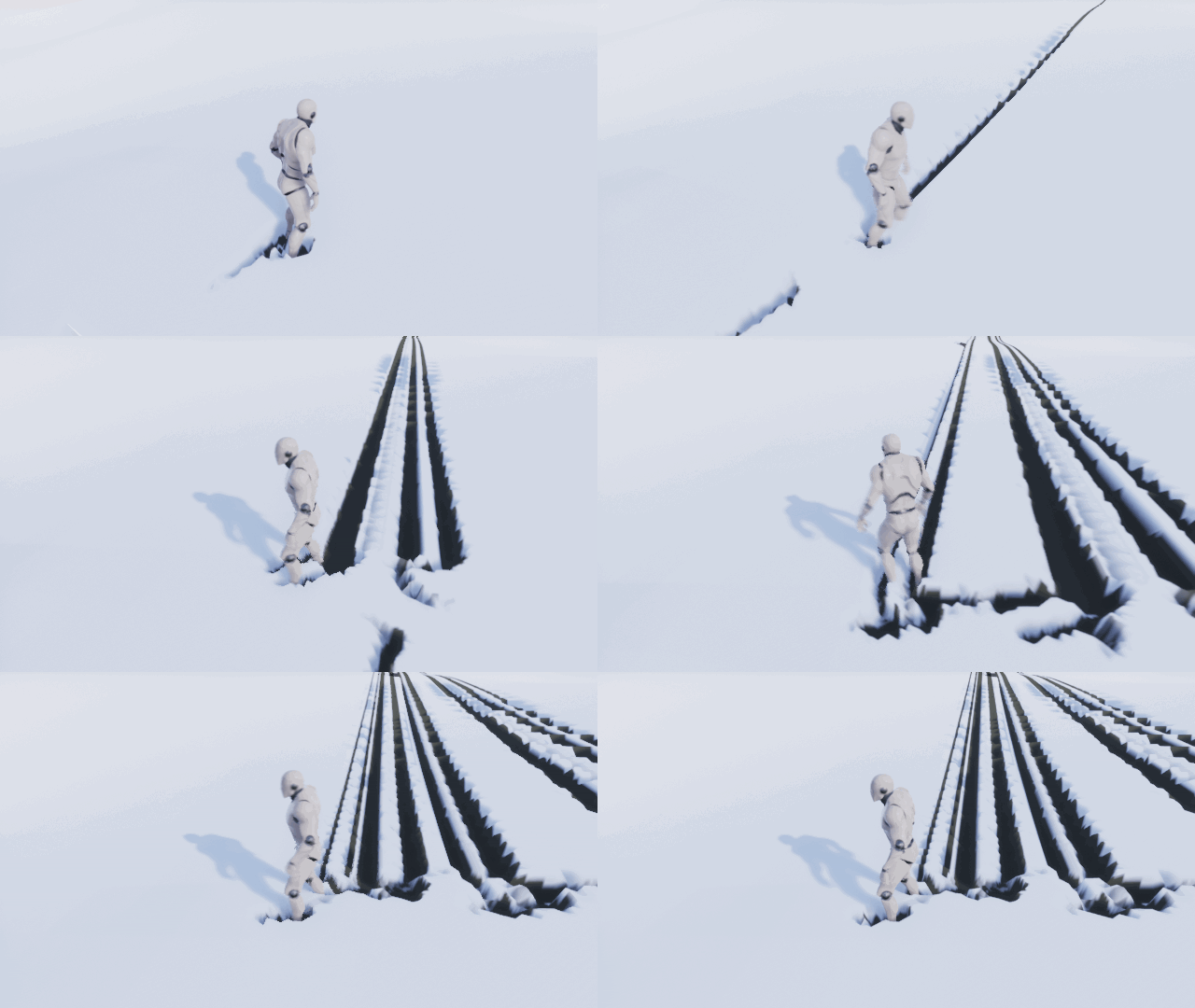
To fix this, we need to mask all UVs that are outside the range from 0 to 1 (that is, the capture area). For this, I created the function MF_MaskUV0-1 . It returns 0 if the transmitted UV is outside the range from 0 to 1 and returns 1 if within it. Multiplying the result by the target render, we perform the masking.
Now that we have projected the target render, we can use it to mix colors and offset vertices.
Using target render
Let's start by mixing colors. To do this, we simply connect 1-x with Lerp :

Note: if you do not understand why I use 1-x , I will explain - it is necessary to invert the target render, so that the calculations become a little easier.
Now that we have a track, the color of the earth turns brown. If there is no color, it remains white.
The next step is to move the vertices. To do this, add the selected nodes and connect everything as follows:

This will lead to the fact that all snow areas will move up by 25 units. Areas without snow have zero offset, thereby creating a footprint.
Note: You can change the DisplacementHeight to increase or decrease the level of snow. Also note that DisplacementHeight is the same value as the capture offset. When they have the same value, it gives us an exact deformation. But there are cases when it is necessary to change them separately, so I left them with separate parameters.
Click on Apply and return to the main editor. Create an instance of BP_Capture at the level and give it coordinates (0, 0, -2000) to place it underground. Click on Play and wander around using the W , A , S and D keys to warp the snow.
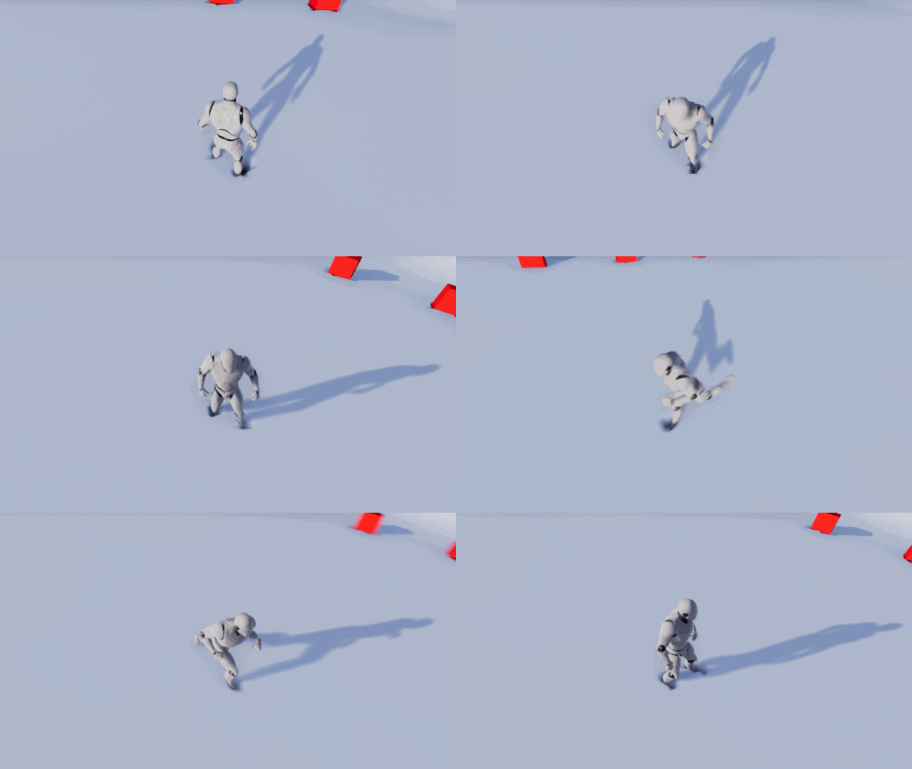
Deformation works, but there is no trace! This happened because the capture overwrites the target render each time the capture is performed. We need some way to make traces permanent .
Creating permanent tracks
To create persistence, we need another target render ( constant buffer ), in which all the contents of the capture will be saved before overwriting. Then we will add a permanent buffer to the capture (after rewriting it). We get a cycle in which each target render writes to the other. This is how we create the permanence of the tracks.
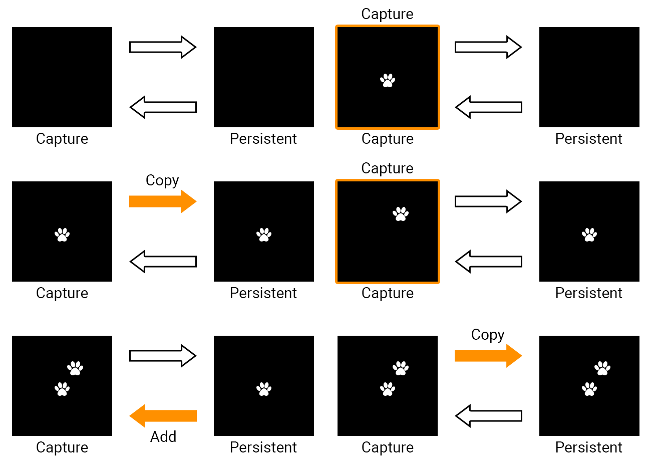
First, we need to create a permanent buffer.
Creating a permanent buffer
Navigate to the RenderTargets folder and create a new Render Target called RT_Persistent . In this tutorial, we will not have to change the texture parameters, but in your own project you will need to make sure that both target renders use the same resolution.
Next, we need a material that will copy the capture to a permanent buffer. Open Materials \ M_DrawToPersistent and add a Texture Sample node . Select the RT_Capture texture for it and connect it as follows:
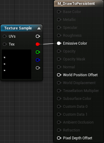
Now we need to use the draw material. Click Apply , and then open BP_Capture . First, create a dynamic copy of the material (later we will need to transfer values to it). Add selected nodes to Event BeginPlay :

Nodes Clear Render Target 2D purified before using each target rendering.
Then open the DrawToPersistent function and add the selected nodes:

Next, we need to make the rendering to a permanent buffer be performed in each frame, because the capture takes place in each frame. To do this, add DrawToPersistent to the Event Tick .
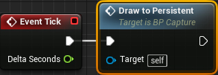
Finally, we need to add a constant buffer back to the target render capture.
Record back to capture
Click on Compile and open PP_DepthCheck . Then add the selected nodes. For Texture Sample, set the value of RT_Persistent :

Now that the target renders write to each other, we’ll get traces remaining. Click on Apply , and then close the material. Click on Play and start leaving tracks!
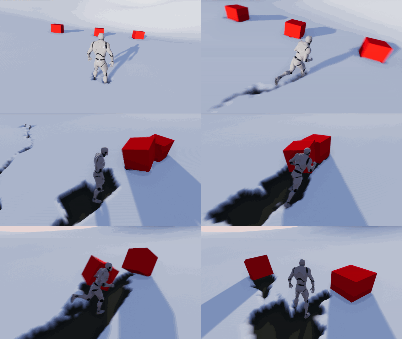
The result looks great, but the resulting scheme only works for one area of the map. If you go beyond the capture area, the traces will cease to appear.
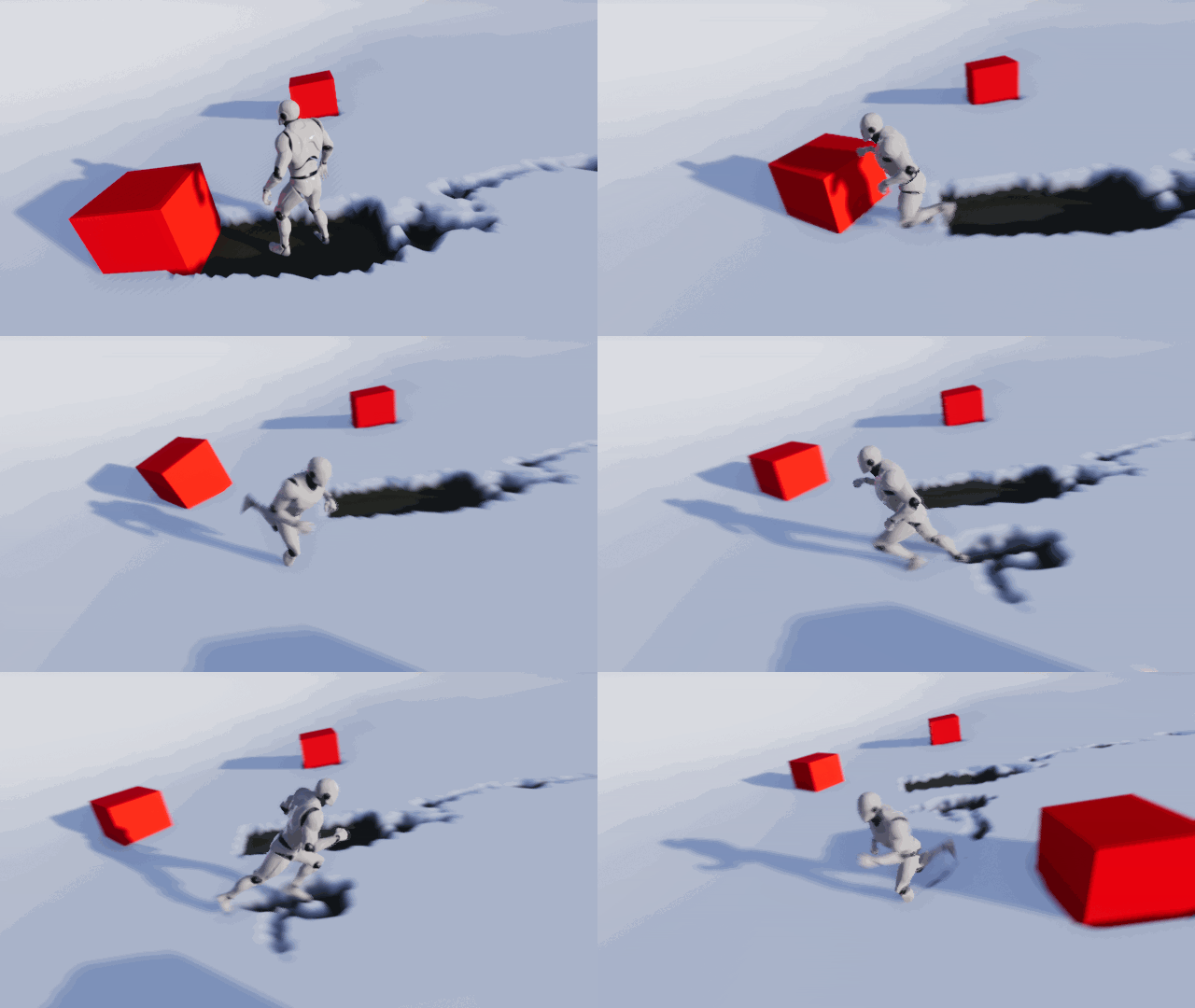
You can solve this problem by moving the capture area along with the player. This means that the tracks will always appear around the area in which the player is located.
Note: as the capture is moved, all information outside the capture area is removed. This means that if you return to the area where there were already traces, they will disappear. In the next tutorial I will explain how to create partially conserved traces.
Move Capture
It can be decided that it is sufficient to simply bind the XY capture position to the XY player position. But if you do this, then the target render will begin to blur. This is because we move the target render in increments that are smaller than a pixel. When this happens, the new pixel position is between the pixels. As a result, several pixels are interpolated by one pixel. Here's what it looks like:
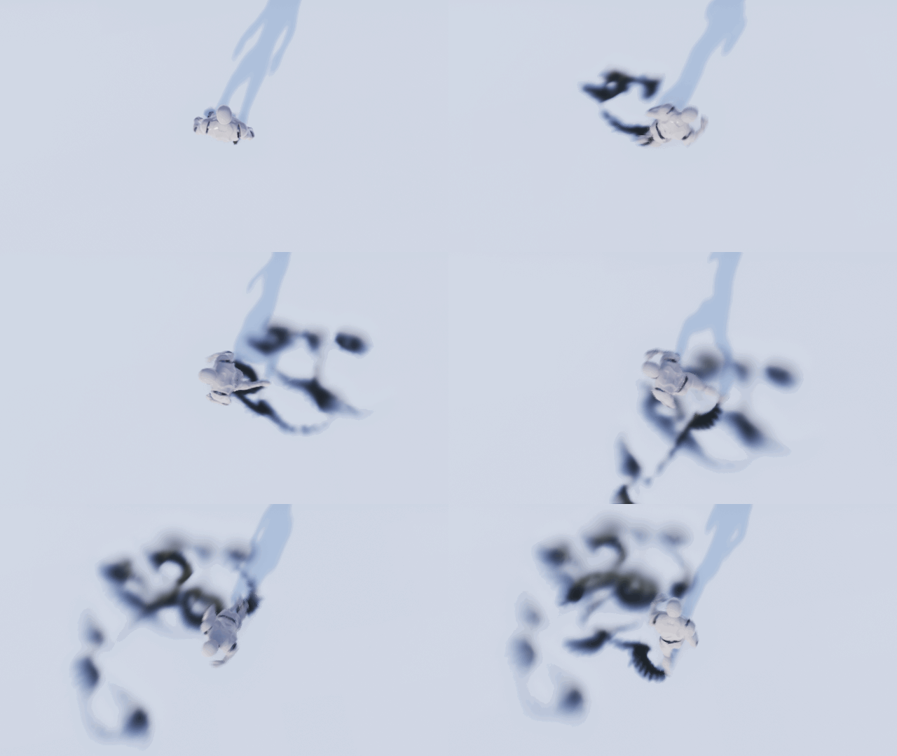
To fix this problem, we need to move the grab in discrete steps. We calculate the pixel size in the world , and then move the capture to steps equal to that size. Then each pixel will never be between the others, so the blur will not appear.
First, let's create a parameter in which the capture location will be stored. He will need the material of the earth to perform the projection calculations. Open MPC_Capture and add a Vector Parameter called CaptureLocation .

Next, you need to update the ground material to use the new parameter. Close MPC_Capture and open M_Landscape . Modify the first part of the projection calculation as follows:
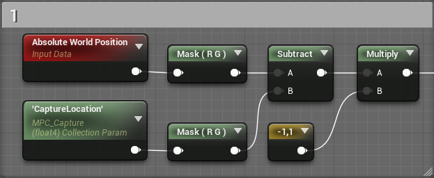
Now the target render will always be projected onto the capture location. Click on Apply and close the material.
Next, we will make the capture move in a discrete step.
Moving Capture in Discrete Pitch
To calculate the size of a pixel in the world, you can use the following equation:
(1 / RenderTargetResolution) * CaptureSizeTo calculate the new position, we use the equation below for each component of the position (in our case, for the X and Y coordinates).
(floor(Position / PixelWorldSize) + 0.5) * PixelWorldSizeNow we use them in blueprint capture. To save time, I created the SnapToPixelWorldSize macro for the second equation . Open BP_Capture , and then open the MoveCapture function . Next, create the following scheme:

It will calculate the new location, and then keep the difference between the new and the current location in MoveOffset . If you use a resolution other than 256 × 256, then change the highlighted value.
Next, add the selected nodes:

This scheme will move the grab with the calculated offset. It will then save the new capture location in MPC_Capture so that it can be used by the earth material.
Finally, we need to perform a position update in each frame. Close the function and add an Event Tick in front of DrawToPersistent MoveCapture .

The capture move is only half the solution. We also need to move the constant buffer. Otherwise, the capture and persistent buffer will be out of sync and will create weird results.
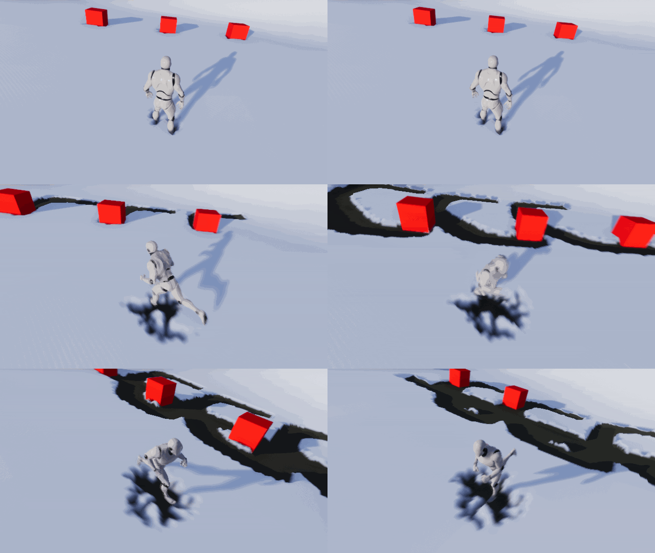
Moving Permanent Buffer
To shift the constant buffer, we need to pass the calculated displacement offset. Open M_DrawToPersistent and add the selected nodes:

Due to this, the constant buffer will shift by the amount of the transferred offset. As in the material of the earth, we need to turn the X coordinate and disguise it. Click on Apply and close the material.
Then you need to pass the offset. Open BP_Capture , and then open the DrawToPersistent function . Next, add the selected nodes:

So we convert the MoveOffset to a UV space, and then transfer it to the rendering material.
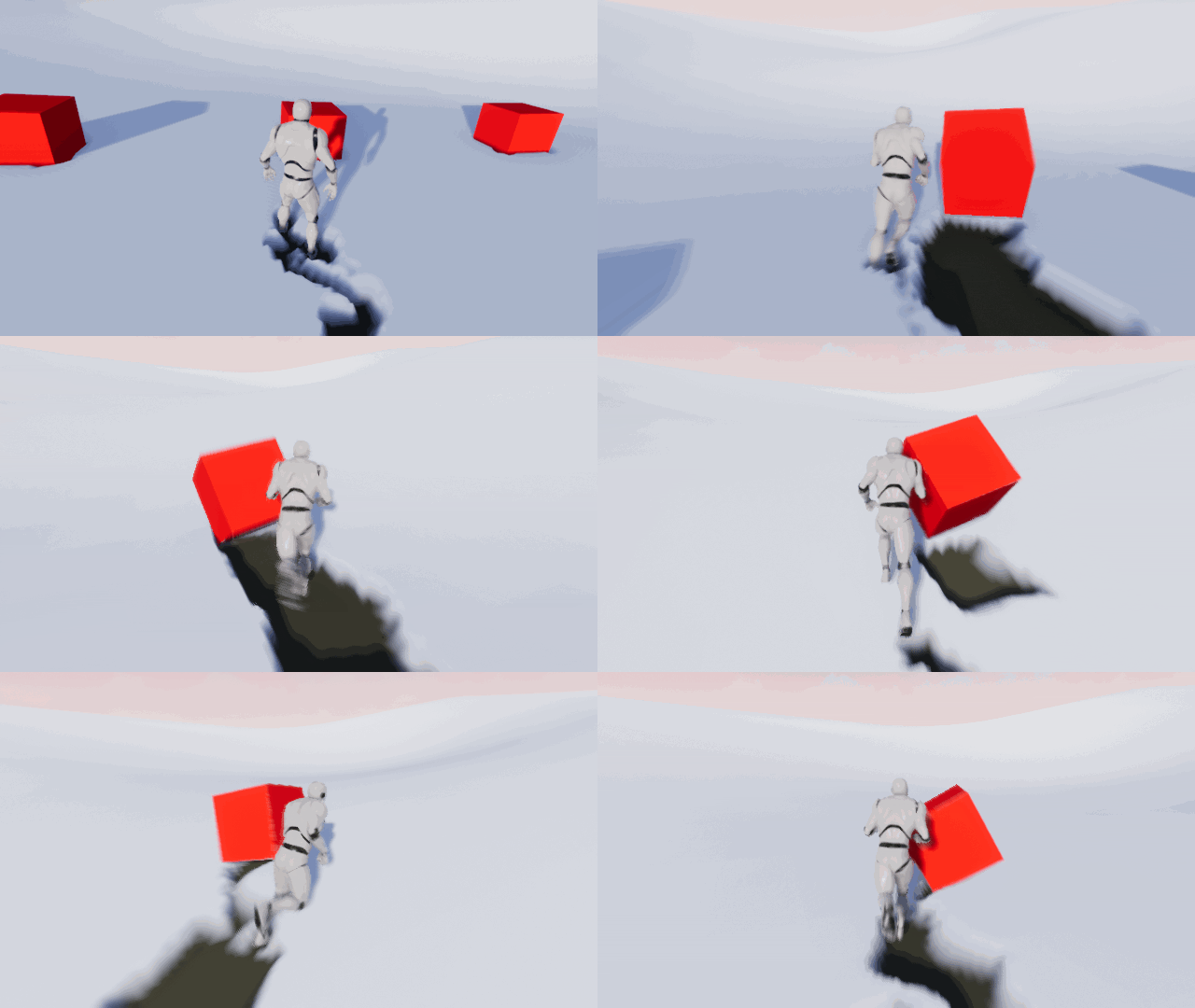
Click on Compile , and then close the blueprint. Click on Play and run your best! No matter how far you run, there will always be traces around you.
Where to go next?
The finished project can be downloaded from here.
It is not necessary to use traces created in this tutorial only for snow. You can even apply them to things like crushed grass (in the next tutorial, I will show you how to create an advanced version of the system).
If you want to work with landscapes and target renderers, I recommend watching the video of Chris Murphy Building High-End Gameplay Effects with Blueprint . From this tutorial you will learn how to create a huge laser that burns earth and grass!
