 May 30, 2012 at 20:35
Tricopter on the Crius MultiWii controller
ATTENTION, the article is outdated, but it can still be used for educational purposes.
Inspired by the article from rcexplorer about the simple construction of a copter ( here is my translation ), I made myself a small flying unit with 3 motors, but with different brains and an aluminum beam base instead of wood.
I will be silent about some things, as they are described in detail in a previous article .
The frame is very simple. We take a piece of fiberglass or other similar thin and durable material, cut out two parts of the central part of the desired size and, fastening the resulting parts with two-sided tape, drill 6 holes in them for attaching the beams: 2 holes per beam, and each beam at an angle of 120 degrees. In this case, it is advisable to pre-calculate the distance from the axis of the motor to the center of the beam connection, otherwise there may be problems with the future configuration of the flight controller.
If you don’t know where to find fiberglass, you can always order on taydaelectronics.com, one 6 by 6 inch square costs a little more than $ 1, but you need to buy at least 5 pieces to meet the minimum weight of the package.
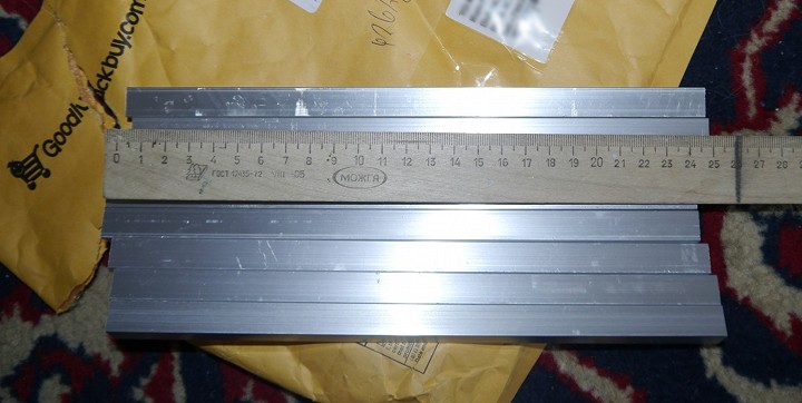
Now we need a lightweight and durable aluminum profile. Since I was lazy to go shopping and time was running out, I ordered a set of 4 rays , 25 cm long each from the GoodLuckBuy website.
I usually figure out the location and dimensions in inkscape, then leave the outline, print and stick to the workpiece.
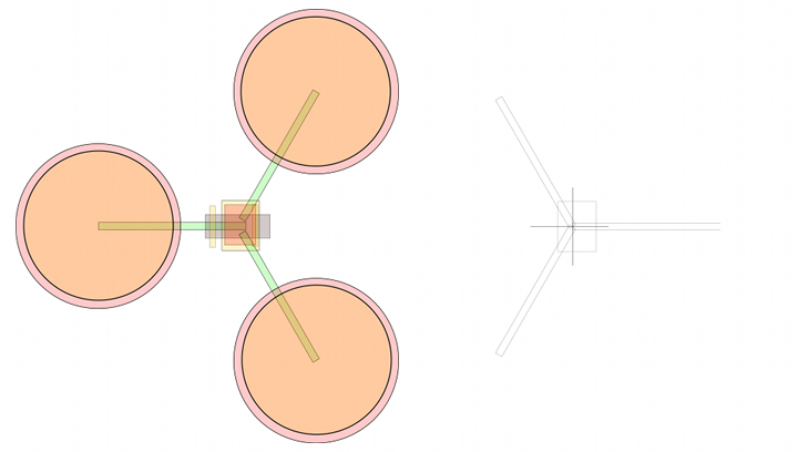
At the time of construction, I had only a small piece of foil fiberglass, so I got two rectangles measuring 65 by 85 mm. In which 4 more holes were later made for mounting the suspension with a battery and a camera.
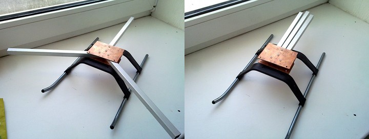
As a result, we got such a frame, fastened with plastic bolts and nuts, which, moreover, does not fold badly (later it will not be so beautiful, but still compact)
The most difficult and problematic place of the tricopter is the rotary mechanism of the rear motor, which serves to compensate for rotation, as well as to rotate. That's just because of him for a long time hesitated to build a "three rubles", but really wanted in view of the economy and the ability to easily fold the frame for transportation. As in David’s article, I took these things :

But there was an error with the servo (I wanted to save a little, but I had to buy it twice), so the first version of the mechanism turned out to be quite large and heavy.

Therefore, I recommend immediately taking the servo BMS-385DMAX, indicated in the article by David .
Note that the screed holding the swivel mechanism does not fly off, you should slightly bend the profile. I also recommend screwing a small piece of wood into the recess of the white block of the mechanism, as well as using 2-sided tape or glue.
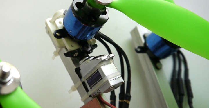
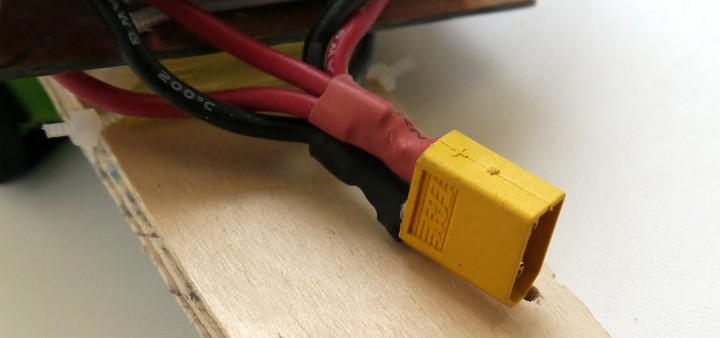
By tradition (and it was available at home) HobbyKing BlueSeries 30A speed controllers and 20-22L motors . Speed controllers had to lengthen the power wires in order to conveniently pull out the power connector , and even to reach the battery . And of course, you need to slightly change the settings of the speed controllers, turn on Brake, increase Timing to High and remove smooth acceleration (different speed controllers have different parameters, but in general set everything so that it is faster).
Propellers are multidirectional, according to the rotations of the motors: the front left rotates clockwise, the front right counterclockwise, and the rear, depending on your settings (recall that to change the direction of rotation it is enough to swap any 2 wires from the speed controller to the motor in some places).
The gimbal in this case is just plywood cut to fit the width of the battery. Velcro is glued onto the plywood (the other part on the battery) and at the same time an additional Velcro is threaded for reliable battery fastening. Silicone tubes

are attached to the suspension via screeds , other silicone tubes are attached to the frame on the screeds, and then fastened together to damp the vibration on the camera. So that the copter does not land on the battery (which is extremely dangerous), 3 small rectangles can be cut out from the remnants of the PCB and, after drilling holes in them, fixed to the beams with ties.

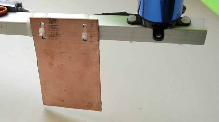
With a relatively hard landing, the screeds fall off, absorbing most of the energy of the fall, so the battery does not suffer (tested in a fall from 7 meters on the asphalt).
Not so long ago, a very cheap flight controller with atmega328p and a set of sensors appeared on the goodluckbuy website: a gyroscope + accelerometer for the Lite version and additional barometer and compass for the Standart version . I took the Lite version for two reasons: the price (at the time of purchase, the difference was 2 times) and the senselessness of other sensors (the course perfectly holds without a compass, and keeping the height with jumps + -2 meters on the bmp085 sensor does not inspire me).

After the purchase, I recommend to pick out all the excess and rinse the handkerchief in alcohol, since almost all the Chinese have left a lot of conductive dirt that closes the contacts and can simply kill the controller.

We fix the board and related equipment (receiver) to the frame using foamed adhesive tape . It holds very firmly, and at the same time eliminates vibration a bit. (only do not mount the antenna so if you intend to fly far).
The weight of the copter is about 800 grams, the flight time with a 2.2Ah battery and camera up to 200 grams is about 10 minutes, while the power reserve is still about 40-50%.
This ends the iron part and begins the game with software.
After the first connection of the board, it turned out that the uploaded firmware is quite old, and even with the sensor axes mixed up, i.e. you don’t even have to try to fly on such a one. Therefore, download the Arduino IDE and the new firmware (do not download dev!), Or even better, the port from mahowik with a bunch of improvements.
Open the sketch firmware through the Arduino IDE. The entire configuration is described in the config.h file (more details about most parameters and settings can be found here , in this article many little things are omitted). For the tricopter, set the frame type #define TRI, the sensor board type #define CRIUS_LITE and the filter for the gyroscope #define ITG3200_LPF_42HZ. And now in the Arduino IDE settings, select any 328p arduino and fill in the resulting sketch.
Launch MultiWiiConf for your system.

Since our swivel mechanism uses a servo that has the ability to burn under heavy loads, it is better to find out and set the limits of servo deviations. To do this, with the YAW stick on the control panel, reject the servo left and right and remember the maximum and minimum value of SERVO in its extreme positions, then enter these values in the config.h file
And reload the sketch into the controller. Now you can try to take off, but note that the copter will rotate, so trim the YAW channel on the remote control so that there are no rotations during takeoff and flight, and then go back to MultiWiiConf, look at this value in the SERVO field and change it to
ATTENTION! In the new firmware (2.0 and higher), such trimming is done through an LCD screen or terminal, if you do not have either one, then you will have to slightly change the code in Output.ino
Ready-made configuration file for my tricopter nekaka.com/d/sgNj8AXp2Y - maybe someone will come in handy.
Now you can configure the PID , add camera gimbal control, etc. , as well as add GPS support with functions to hold the position and return home.
In fact, when building and setting up there will be a lot of incomprehensible and interesting. But engaging in aircraft modeling is addictive, and engaging in copters is addictive, especially if you are a programmer and have a desire to improve the code of one of the open source projects.
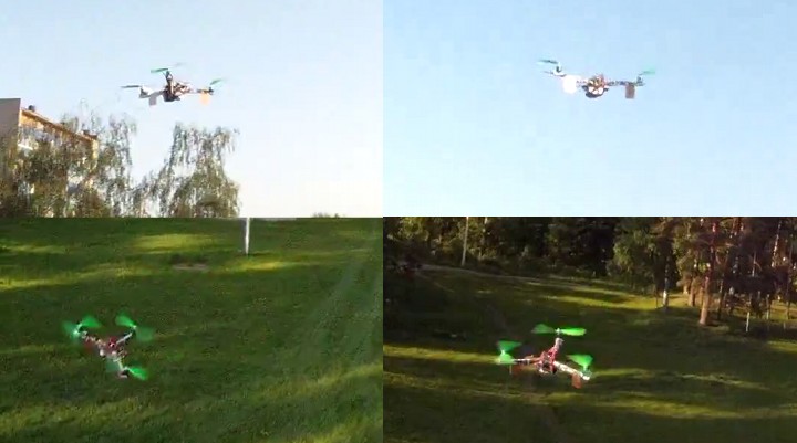
And in conclusion, a video of a recent flight, during which the copter was badly damaged, but was quickly repaired right there on the field (thanks to the couplers and plastic bolts).
The shooting was carried out from 2 devices: a quadrocopter with a GoPro camera and my tricopter with an onboard FPV camera, a picture of which was recorded on the ground on an old miniDV camera.
ps: if you have any questions - ask, I will update the article as far as possible.
Inspired by the article from rcexplorer about the simple construction of a copter ( here is my translation ), I made myself a small flying unit with 3 motors, but with different brains and an aluminum beam base instead of wood.
I will be silent about some things, as they are described in detail in a previous article .
Frame
The frame is very simple. We take a piece of fiberglass or other similar thin and durable material, cut out two parts of the central part of the desired size and, fastening the resulting parts with two-sided tape, drill 6 holes in them for attaching the beams: 2 holes per beam, and each beam at an angle of 120 degrees. In this case, it is advisable to pre-calculate the distance from the axis of the motor to the center of the beam connection, otherwise there may be problems with the future configuration of the flight controller.
If you don’t know where to find fiberglass, you can always order on taydaelectronics.com, one 6 by 6 inch square costs a little more than $ 1, but you need to buy at least 5 pieces to meet the minimum weight of the package.
Now we need a lightweight and durable aluminum profile. Since I was lazy to go shopping and time was running out, I ordered a set of 4 rays , 25 cm long each from the GoodLuckBuy website.
I usually figure out the location and dimensions in inkscape, then leave the outline, print and stick to the workpiece.
At the time of construction, I had only a small piece of foil fiberglass, so I got two rectangles measuring 65 by 85 mm. In which 4 more holes were later made for mounting the suspension with a battery and a camera.
As a result, we got such a frame, fastened with plastic bolts and nuts, which, moreover, does not fold badly (later it will not be so beautiful, but still compact)
Swivel mechanism
The most difficult and problematic place of the tricopter is the rotary mechanism of the rear motor, which serves to compensate for rotation, as well as to rotate. That's just because of him for a long time hesitated to build a "three rubles", but really wanted in view of the economy and the ability to easily fold the frame for transportation. As in David’s article, I took these things :
But there was an error with the servo (I wanted to save a little, but I had to buy it twice), so the first version of the mechanism turned out to be quite large and heavy.
Therefore, I recommend immediately taking the servo BMS-385DMAX, indicated in the article by David .
Note that the screed holding the swivel mechanism does not fly off, you should slightly bend the profile. I also recommend screwing a small piece of wood into the recess of the white block of the mechanism, as well as using 2-sided tape or glue.
Speed controllers, motors and propellers
By tradition (and it was available at home) HobbyKing BlueSeries 30A speed controllers and 20-22L motors . Speed controllers had to lengthen the power wires in order to conveniently pull out the power connector , and even to reach the battery . And of course, you need to slightly change the settings of the speed controllers, turn on Brake, increase Timing to High and remove smooth acceleration (different speed controllers have different parameters, but in general set everything so that it is faster).
Propellers are multidirectional, according to the rotations of the motors: the front left rotates clockwise, the front right counterclockwise, and the rear, depending on your settings (recall that to change the direction of rotation it is enough to swap any 2 wires from the speed controller to the motor in some places).
Gimbal, battery and racks
The gimbal in this case is just plywood cut to fit the width of the battery. Velcro is glued onto the plywood (the other part on the battery) and at the same time an additional Velcro is threaded for reliable battery fastening. Silicone tubes
are attached to the suspension via screeds , other silicone tubes are attached to the frame on the screeds, and then fastened together to damp the vibration on the camera. So that the copter does not land on the battery (which is extremely dangerous), 3 small rectangles can be cut out from the remnants of the PCB and, after drilling holes in them, fixed to the beams with ties.
With a relatively hard landing, the screeds fall off, absorbing most of the energy of the fall, so the battery does not suffer (tested in a fall from 7 meters on the asphalt).
Crius Lite Flight Controller
Not so long ago, a very cheap flight controller with atmega328p and a set of sensors appeared on the goodluckbuy website: a gyroscope + accelerometer for the Lite version and additional barometer and compass for the Standart version . I took the Lite version for two reasons: the price (at the time of purchase, the difference was 2 times) and the senselessness of other sensors (the course perfectly holds without a compass, and keeping the height with jumps + -2 meters on the bmp085 sensor does not inspire me).
After the purchase, I recommend to pick out all the excess and rinse the handkerchief in alcohol, since almost all the Chinese have left a lot of conductive dirt that closes the contacts and can simply kill the controller.
We fix the board and related equipment (receiver) to the frame using foamed adhesive tape . It holds very firmly, and at the same time eliminates vibration a bit. (only do not mount the antenna so if you intend to fly far).
The weight of the copter is about 800 grams, the flight time with a 2.2Ah battery and camera up to 200 grams is about 10 minutes, while the power reserve is still about 40-50%.
This ends the iron part and begins the game with software.
Software
After the first connection of the board, it turned out that the uploaded firmware is quite old, and even with the sensor axes mixed up, i.e. you don’t even have to try to fly on such a one. Therefore, download the Arduino IDE and the new firmware (do not download dev!), Or even better, the port from mahowik with a bunch of improvements.
Customization
Open the sketch firmware through the Arduino IDE. The entire configuration is described in the config.h file (more details about most parameters and settings can be found here , in this article many little things are omitted). For the tricopter, set the frame type #define TRI, the sensor board type #define CRIUS_LITE and the filter for the gyroscope #define ITG3200_LPF_42HZ. And now in the Arduino IDE settings, select any 328p arduino and fill in the resulting sketch.
Launch MultiWiiConf for your system.
Since our swivel mechanism uses a servo that has the ability to burn under heavy loads, it is better to find out and set the limits of servo deviations. To do this, with the YAW stick on the control panel, reject the servo left and right and remember the maximum and minimum value of SERVO in its extreme positions, then enter these values in the config.h file
/* you can change the tricopter servo travel here */
#define TRI_YAW_CONSTRAINT_MIN 1340
#define TRI_YAW_CONSTRAINT_MAX 1855
And reload the sketch into the controller. Now you can try to take off, but note that the copter will rotate, so trim the YAW channel on the remote control so that there are no rotations during takeoff and flight, and then go back to MultiWiiConf, look at this value in the SERVO field and change it to
#define TRI_YAW_MIDDLE 1630 // tail servo center pos. - use this for initial trim; later trim midpoint via LCD
ATTENTION! In the new firmware (2.0 and higher), such trimming is done through an LCD screen or terminal, if you do not have either one, then you will have to slightly change the code in Output.ino
  #ifdef TRI
    motor[0] = PIDMIX( 0,+4/3, 0); //REAR
    motor[1] = PIDMIX(-1,-2/3, 0); //RIGHT
    motor[2] = PIDMIX(+1,-2/3, 0); //LEFT
    servo[5] = constrain(TRI_YAW_MIDDLE + YAW_DIRECTION * axisPID[YAW], TRI_YAW_CONSTRAINT_MIN, TRI_YAW_CONSTRAINT_MAX); //REAR
  #endif
Ready-made configuration file for my tricopter nekaka.com/d/sgNj8AXp2Y - maybe someone will come in handy.
Now you can configure the PID , add camera gimbal control, etc. , as well as add GPS support with functions to hold the position and return home.
Conclusion
In fact, when building and setting up there will be a lot of incomprehensible and interesting. But engaging in aircraft modeling is addictive, and engaging in copters is addictive, especially if you are a programmer and have a desire to improve the code of one of the open source projects.
And in conclusion, a video of a recent flight, during which the copter was badly damaged, but was quickly repaired right there on the field (thanks to the couplers and plastic bolts).
The shooting was carried out from 2 devices: a quadrocopter with a GoPro camera and my tricopter with an onboard FPV camera, a picture of which was recorded on the ground on an old miniDV camera.
ps: if you have any questions - ask, I will update the article as far as possible.









