System for compensating the error of fiber optic installation during its processing by laser radiation in the process of rotation
Section 1. Relevance
Currently, endovasal laser coagulation of varicose veins (EVLK) is a modern and effective method of treating varicose veins. The composition of medical devices for laser coagulation of varicose veins includes a fiber instrument (light guide) with a radial radiation output (Fig. 1), through which the radiation directly affects the biological tissue. The effectiveness and safety of treatment depends on the configuration and quality of processing of this instrument.
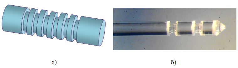
Fig.1 Possible relief of fiber: a) - model of the workpiece, b) enlarged image of the processed workpiece
For processing by laser radiation, the light guide is installed in a cam cartridge of a special lathe. The installation process includes basing and consolidation. The actual position of the installed workpiece differs from the deviation required by a certain amount - the installation error:
\ begin {eqnarray}
\ triangle \ varepsilon_y & = & f (\ triangle \ varepsilon_b, \ triangle \ varepsilon_z),
\ end {eqnarray}
-- base error, mm;
-- fixing error, mm.
In the process of mass production, the processed light guide is installed without alignment. In the general case, the geometric axis of the fiber does not coincide with the axis of rotation of the cartridge, which leads to the beating L. in the process of rotation of the workpiece.
Experimental data on the measurement of beating when fixing various diameters of the processed optical fibers showed that its value can reach 250 μm, which does not allow processing of the fiber with laser radiation with sufficient accuracy for practical use. The elimination of the beats produced by adjusting the chuck jaws is not acceptable due to the high labor intensity, time consuming and significant subjective assessment of the person - the machine operator in the adequacy of eliminating the beating. Therefore, an urgent task is posed: to develop a principle that ensures the compensation of the beating during fiber processing.
Section 2. Installation Description
The machine for laser processing of the fiber is a motorized table that provides movement of the fiber in three longitudinal axes X, Y, K and rotation in the axes E and W (Fig.2).
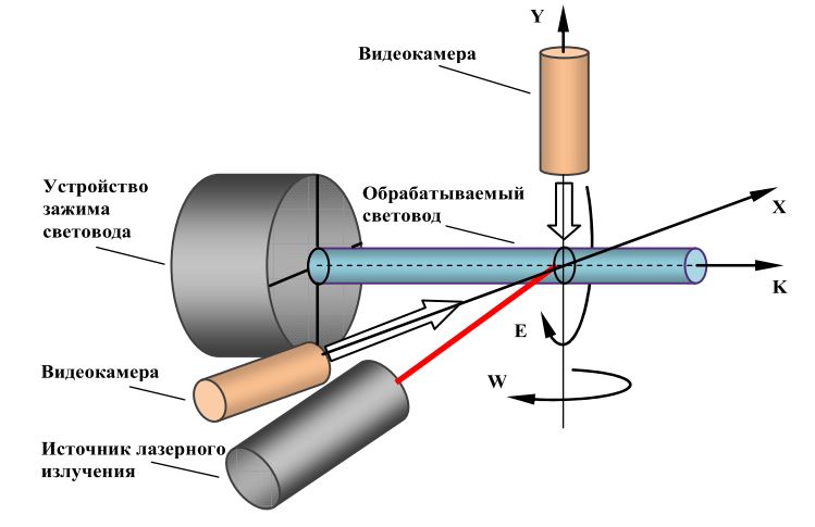
Fig. 2 - An explanatory drawing of the installation diagram
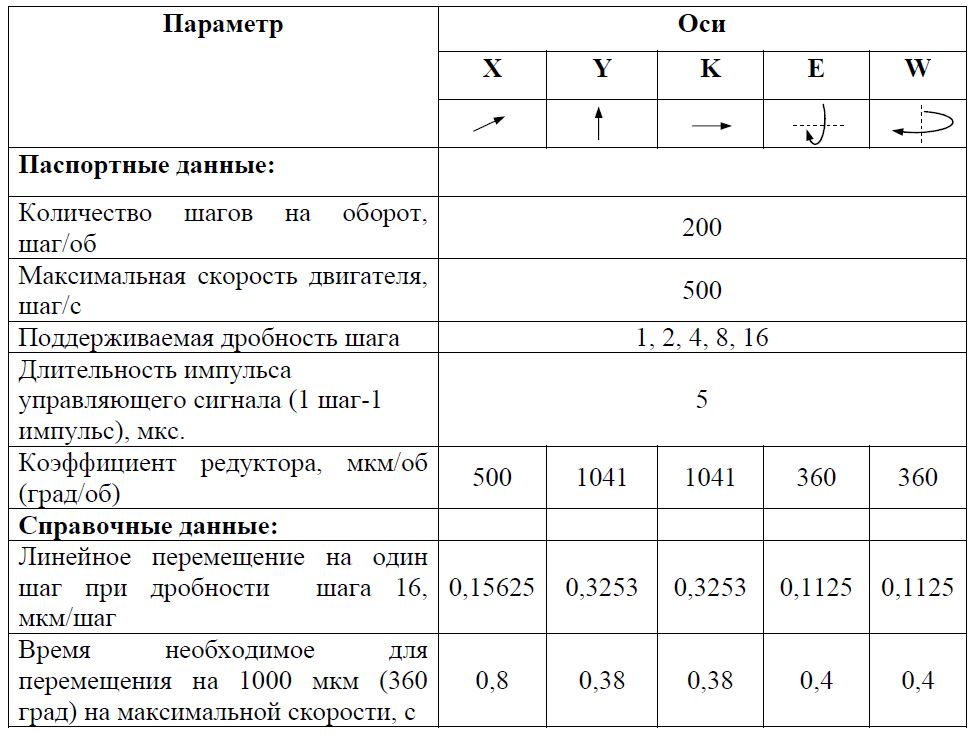
Movement along the X, Y, K axes is ensured by a pair of gearmotor, along the E and W axes - by a motor. The motor is a stepper motor controlled by a local controller - driver (Toshiba TB6600HG). The driver's input signals are two TTL level signals providing the setting of the direction and speed of the stepper motor. The rotation speed is determined by the repetition rate of rectangular pulses. The output shaft of the engine of each of the axes X, Y, K is rigidly connected with the gearbox, which provides a change in the rotational type of motion at the input to the translational one at its output. Movement along the axes X, Y, K is limited on both sides by end sensors. The position control system on each axis is open. Technical parameters of axle drives are presented in Table. 1.
Tab. 1 - Technical parameters of axle drives
The processing object is a fiber with a diameter of 330 μm, which is fixed in a clamping device - a cartridge (Fig. 2). The cartridge provides mounting and rotation of the fiber.
The processing tool is a CO2 laser with a wavelength of 11 microns.
Section 3. Beat Compensation
3.1 Problem Statement
When clamping the workpiece - the light guide in the chuck of the machine its center gets offset - L relative to the center of the cartridge - point (coordinate system center). This offset has a different meaning for each fixing of the fiber. When rotating Fig.4a center of the fiberdescribes a circle of radius L - beating value. The goal is to reduce the amount of beating.
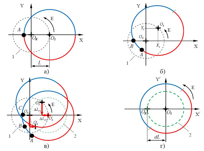
Fig. 4 - The relative position of the axis of the cartridge and the fixed fiber during rotation: a) the amount of beats when the sample is fixed in the cartridge of the machine; b) turning the cartridge 45 degrees in one step of the engine; c) the introduction of corrective amendments to the position of the axis of the cartridge; d) the movement of the axis of the cartridge relative to the fixed axis of the light guide with compensation for each step of the engine.
3.2 Principle of the proposed solution
Consider the movement of the fiber in the plane when it rotates about the axis of the cartridge - point .
Let at the initial moment of time the axis of the workpiece is a pointis located on the X axis and has coordinates (L, 0) and the laser beam hits the surface of the fiber at point A (Fig. 4a).
For clarity, rotate the cartridge at an anglein one step of the engine (Fig.4b). At the same time:
- point gets coordinates ;
- the projections of the magnitude of the beating L on the X-axis and Y will take values, ;
- the laser beam will move along the surface of the fiber to point B.
When the fiber is rotated, to compensate for the beat value, we need to return the coordinates of the pointto its original position with coordinates (L, 0). For this, it is necessary to introduce corrective corrections to the position of the cartridge point along the X and Y axes of Fig.4b on the size of the projections, . These corrective corrections are carried out at the expense of stepping motors of the axes X, Y. In this case, the pointagain, the initial coordinates will be (L, 0), and the laser beam will hit the point C of the fiber surface.
At the subsequent rotation, new corrective movements of the cartridge axis will be required. With this pointthe axis of the cartridge will move around circle 2 (Fig. 4d). The magnitude of the radius of the circle 2 is equal to the magnitude of the beating L. With this solution of the task, the fiber axis is in relative immobility about its axis, and the axis of the cartridge moves in a circle, therefore we will consider the fiber rotation in the plane regarding the point by moving the coordinate system for this (Fig. 4d).
3.3 Mathematical justification of the proposed solution
The considered principle of beating compensation presupposes the presence of known values of corrective movements. , (increments of beating) of the cartridge at each (i + 1) step of the stepper motor during the rotation of the light guide. To determine them, consider fig.5.

Fig. 5 - The magnitudes of the projections when the fiber is rotated relative to the axis of the cartridge counterclockwise (positive direction)
At each next step of the stepper motor, the rotation axis E will be obtained increments due to the beating L:

where are the coordinatesare determined from the displacement geometry (Fig. 5):


Graphic view of the change in incrementsfor each i step when rotated counterclockwise (fractional increment in E = 4) with a beat of 50 μm is shown in Fig.6.
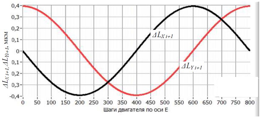
Fig. 6 - Changing the magnitudes of the projections (displacements) at each step of the motor along the X and Y axes caused by the beating when the fiber is rotated 360 degrees counterclockwise (fraction of the step by E = 4) with a beating of 50 μm.
In the absence of compensation, the numerical integration with the corresponding initial conditions for the expressionswill give the current projection on the axis of
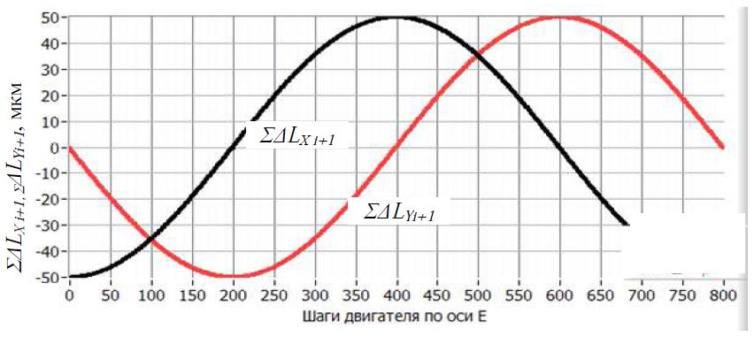
Fig.7 Fig. 7 - The current projections of the displacements at each step of the motor along the X and Y axes due to the beating when the fiber rotates 360 degrees counterclockwise (fraction of the step by E = 4) with the beating L = 50 μm.
In the process of rotation, with the accumulation of the magnitude of the beating is greater than the magnitude of the control action, its compensation must pass. This reflects the following condition:
where - linear displacement along the X axis in one motor step:
- linear displacement along the Y axis in one motor step.
Condition (4) can be modified to obtain a smaller error in beating compensation.
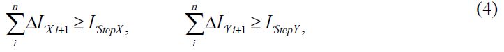
In the presence of compensating pulses, the total displacement, decrease - Fig. 8.
Fig. 8 - Change of size of shiftsalong the X axis in the process of rotation along the E axis with beating compensation. Beating L = 50 µm, initial angle= 0
3.4 Performance Evaluation
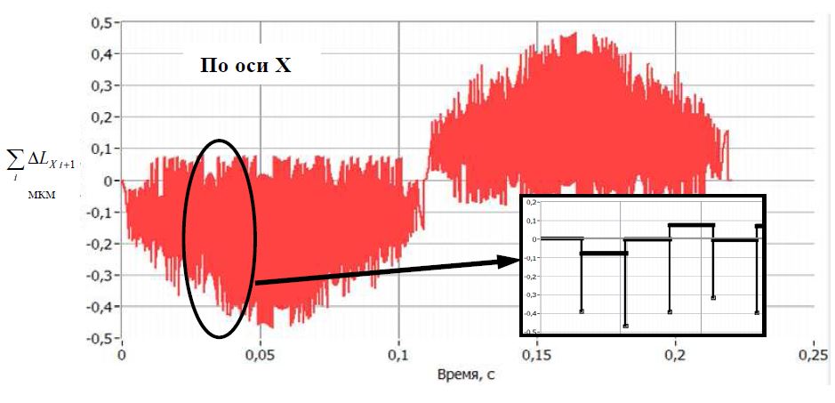
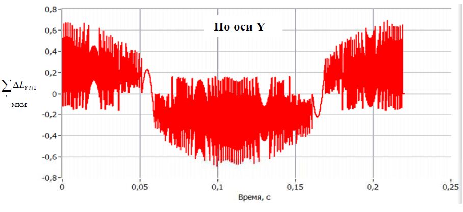
The overall picture of the beating compensation process of L = 50 µm when turning on with the proposed principle is presented in Fig. 9.
a)
b)
Fig. 9 - The magnitudes of displacements along the axes for beating compensation L = 50 μm per one revolution of the fiber: a) for the X axis, b) for the Y axis It is
proposed to evaluate the efficiency of beating compensation by a ratio equal to the ratio of maximum axial displacement in the compensation process to the beat value .
Tab. 2 - Beat compensation efficiency.
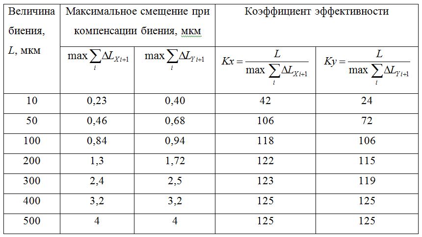
Estimated maximum displacement values. ,for the presented values of the beats and the practical operation of the installation with the proposed principle of the compensation of the beats, it was possible to apply a relief to the light guide using laser radiation with sufficient accuracy for practical application.
It should be noted that when the fiber is processed by laser radiation with beat compensation, the time of one revolution of the fiber relative to its axis will depend on the beat value and change for each treatment. For example, with a beat of 50 microns, the time for one full rotation:
- without beat compensation: 400 ms;
- with beat compensation: 560 ms.
This fact must be taken into account when adjusting the laser power.
Section 4. Determination of the beat
To implement the presented principle of beating compensation, it is required to know its size –L. It is suggested to determine the beating value by a video surveillance system (video camera 1 in fig. 1). In fig. 10. schematically shows a video form from a video camera.
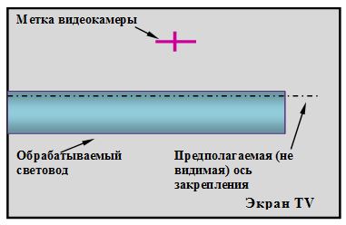
Fig. 10 - Arbitrary arrangement of the fixed fiber on the monitor screen.
To determine the beat value, the following steps must be performed in the specified order:
- to rotate the light guide (E axis) up to the maximum approximation to the mark on the screen (Fig. 11a);
- move the fiber along the coordinates of the X axis to align it with the label (Fig. 11b);
- turn the fiber on (Fig. 11c);
- to move the fiber along the coordinates of the X axis until it coincides with the mark, remembering the distance traveled R (counting the number of motion impulses of a stepper motor) fig. 11g;
- calculate the value of the beating L = R / 2.
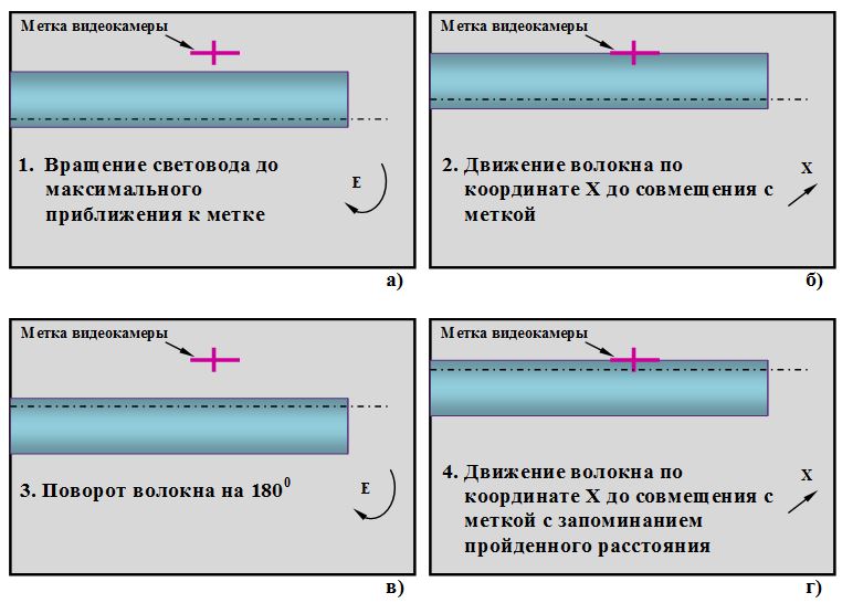
Fig. 11 - Stages of determining the magnitude of the beating of the fiber
Section 5. Conclusion
The proposed principle of beating compensation is implemented on the National Instruments LabVIEW software platform, has been tested, implemented, and showed the effectiveness of its work (Fig. 12).
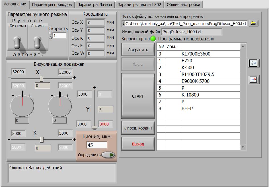
Fig. 12 - The front panel of the program