Learn OpenGL. Lesson 5.5 - Normal Mapping
- Transfer
- Tutorial

Normal mapping
All the scenes we use consist of polygons, in turn, consisting of hundreds, thousands of absolutely flat triangles. We have already managed to slightly enhance the realism of the scenes due to additional details, which are provided by applying two-dimensional textures to these flat triangles. Texturing helps to hide the fact that all objects in the scene are just a collection of many small triangles. Great technique, but its possibilities are not unlimited: when approaching any surface, all one becomes clear that it consists of flat surfaces. Most of the real objects are not completely flat and show a lot of embossed details.
Content
Part 1. Start
Part 2. Basic lighting
Part 3. Loading 3D Models
Part 4. OpenGL advanced features
Часть 5. Продвинутое освещение
- Opengl
- Creating a window
- Hello window
- Hello triangle
- Shaders
- Textures
- Transformations
- Coordinate systems
- Camera
Part 2. Basic lighting
Part 3. Loading 3D Models
Part 4. OpenGL advanced features
- Depth test
- Stencil test
- Mixing colors
- Face clipping
- Frame buffer
- Cubic cards
- Advanced data handling
- Advanced GLSL
- Geometric shader
- Instancing
- Сглаживание
Часть 5. Продвинутое освещение
- Продвинутое освещение. Модель Блинна-Фонга.
- Гамма-коррекция
- Карты теней
- Всенаправленные карты теней
- Normal Mapping
For example, take a brickwork. Its surface is very rough and, obviously, is represented far from plane: it has cavities with cement and many small details like holes and cracks. If the scene with imitation of brickwork is analyzed in the presence of light, then the illusion of the relief of the surface is very easily destroyed. Below is an example of such a scene, containing a plane with applied brickwork texture and one point light source:

As can be seen, the lighting does not at all take into account the details of the relief intended for this surface: all small cracks are absent, and the hollows with cement are indistinguishable from the rest of the surface. It would be possible to use a specular gloss map in order to limit the illumination of certain parts that are located in the surface recesses. But this is more like a dirty hack than a working solution. What we need is a way to provide the equations of illumination with surface microrelief data.
In the context of the lighting equations known to us, consider this question: under what conditions will the surface be lit as ideally flat? The answer is related to the surface normal. From the point of view of the lighting algorithm, information on the shape of the surface is transmitted only through the normal vector. Since the normal vector is constant everywhere on the above surface, the illumination is uniform, corresponding to the plane. And what if the light algorithm is not transmitted to a single normal, constant for all fragments belonging to an object, but a unique normal for each fragment? Thus, the normal vector will vary slightly based on the surface topography, which will create a more convincing illusion of surface complexity:

Due to the use of fragments of different normals, the illumination algorithm will consider the surface as consisting of a set of microscopic planes perpendicular to its normal vector. In the end, this will significantly add the object of texture. The technique of applying normals unique to a fragment, and not the entire surface - this is Normal Mapping or Bump Mapping . Applied to an already familiar scene:
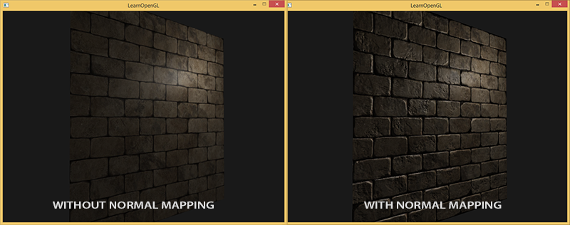
An impressive increase in visual complexity is seen due to the very modest cost of productivity. Since we are all changes in the lighting model are only in the presentation of a unique normal in each fragment, then no formulas for the calculations do not change. Only the input instead of the interpolated surface normal enters the normal for the current fragment. All the same lighting equations do the rest of the work to create an illusion of relief.
Normal mapping
So, it turns out, we need to provide the illumination algorithm with normals, unique for each fragment. We use the method already familiar from the textures of diffuse and specular reflection and use the usual 2D texture to store data about the normal at each point of the surface. Don't be surprised, textures are great for storing normal vectors. Next, we will only have to sample the texture, restore the normal vector and calculate the illumination.
At first glance, it may not be very clear how to store vector data in a regular texture, which is typically used to store color information. But think for a second: the RGB color triad is essentially a three-dimensional vector. Similarly, you can save the components of the XYZ normal vector in the corresponding color components. The magnitudes of the components of the normal vector lie in the interval [-1, 1] and therefore require additional conversion to the interval [0, 1]:
vec3 rgb_normal = normal * 0.5 + 0.5; // переход от [-1,1] к [0,1] Such a reduction of the normal vector to the space of the RGB color components will allow us to preserve the texture of the normal vector obtained on the basis of the real relief of the modeled object and unique for each fragment. An example of such a texture - normal maps - for the same brickwork:

It is interesting to note the blue tint of this normal map (almost all normal maps have a similar shade). This happens because all the normals are oriented approximately along the oZ axis, which is represented by the coordinate triple (0, 0, 1), i.e. in the form of a color triad - pure blue. Small changes in shade are due to the deviation of the normals from the positive oZ semi-axis in some areas, which corresponds to the uneven terrain. So, you can see that on the upper edges of each brick, the texture acquires a green tint. And this is logical: on the upper edges of the brick, the normals should be oriented more towards the oY axis (0, 1, 0), which corresponds to the green color.
For the test scene, we take a plane oriented towards the positive semi-axis oZ and use the following for it.diffuse map and normal map .
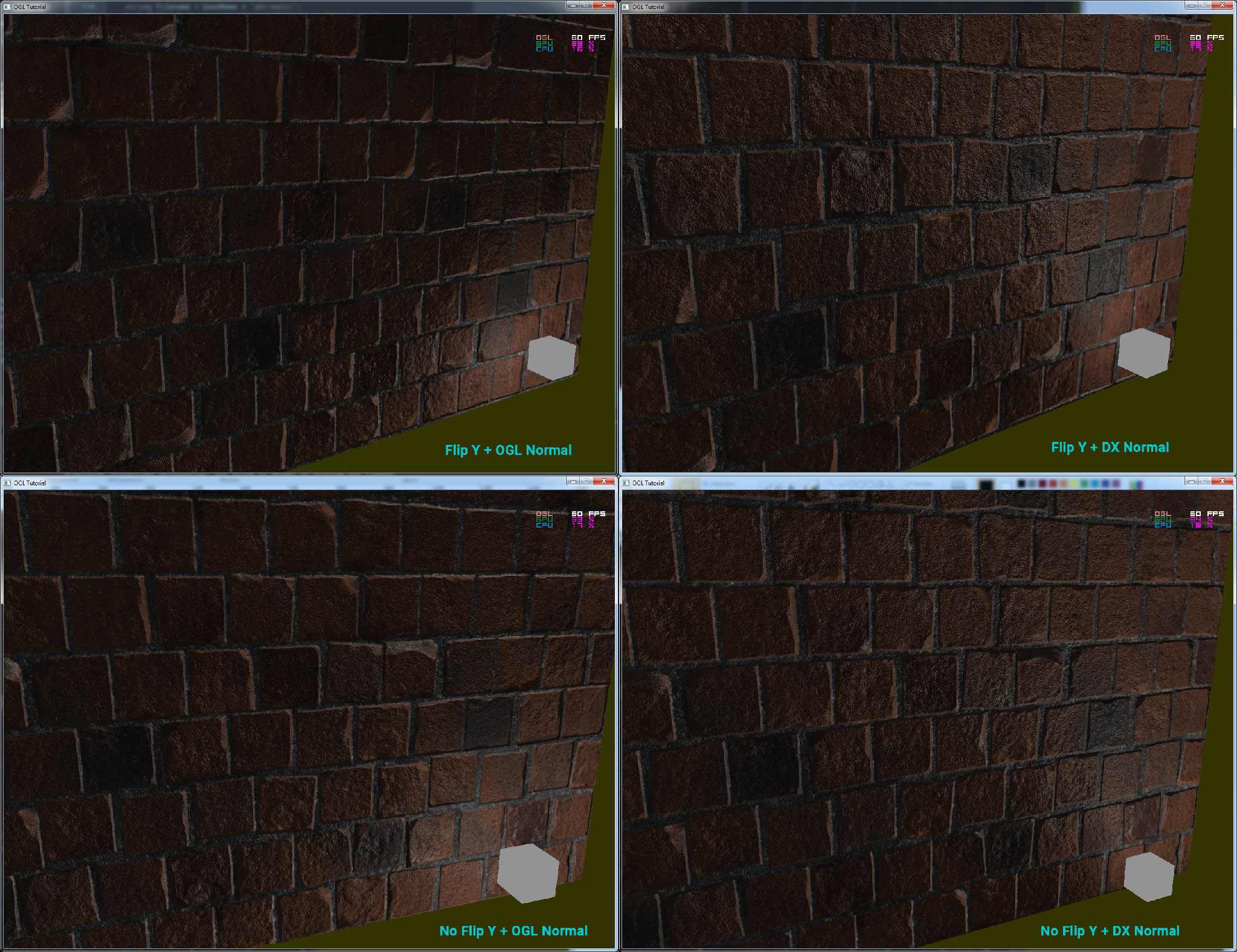
Please note that the normal map on the link and in the picture above are different. In the article, the author rather casually mentioned the reasons for the differences, limiting himself with the advice to transform normal maps to such a form that the green component points “down” rather than “up” in the system local to the texture plane.
If you look in more detail, then two factors interact:
- The difference in how texels are addressed in client memory and in OpenGL texture memory
- The presence of two notations for normal maps. Conventionally, two camps: DirectX-style and OpenGL-style
As for the normal map notation, the two camps that are historically familiar are: DirectX and OpenGL.
As you can see, they are not compatible. And having a little thought one can understand that DirectX considers the tangent space to be left-handed and OpenGL to right-handed. Having slipped the x-card of normals to our application without changes, we get incorrect illumination, and it is not always immediately obvious that it is incorrect. The most noticeable is that the bumps in the OpenGL format become recesses for DirectX and vice versa.
As for addressing: loading data from a texture file into memory, we assume that the first texel is the left upper texel of the image. For the presentation of the texture data in the application's memory, this is generally the case. But OpenGL uses a different texture coordinate system: for it, the first texel is the bottom left. For correct texturing, images are usually turned over along the Y axis even in the code of one or another image file loader. For the Stb_image used in the lessons you need to add a check boxstbi_set_flip_vertically_on_load(1);
What is the most funny, two options are displayed correctly in terms of lighting: the normal map in OpenGL notation with Y reflection turned on or the normal map in DirectX notation with Y reflection turned off. The lighting in both cases works correctly, the difference will remain only in the texture inversion Y.
Note per.
So, let's load both textures, attach them to texture units and render the prepared plane, taking into account the following modifications of the fragment shader code:
uniform sampler2D normalMap;
voidmain(){
    // выборка вектора из карты нормалей с областью значений [0,1]
    normal = texture(normalMap, fs_in.TexCoords).rgb;
    // перевод вектора нормали в интервал [-1,1]
    normal = normalize(normal * 2.0 - 1.0);
    [...]
    // вычисление освещения...
}
Here we apply the inverse transform from the RGB value space to the full normal vector and then simply use it in the familiar Blinna-Phong lighting model.
Now, if you slowly change the position of the light source in the scene, you can feel the illusion of the surface relief provided by the normal map:

But there remains one problem that radically narrows the range of possible use of normal maps. As already noted, the blue tint of the normal map hinted that all the vectors in the texture are oriented on average along the positive oZ axis. In our scene, this did not create problems, because the normal to the surface of the plane was also aligned with oZ. However, what happens if we change the position of the plane in the scene so that the normal to it will be aligned with the positive semi-axis oY?
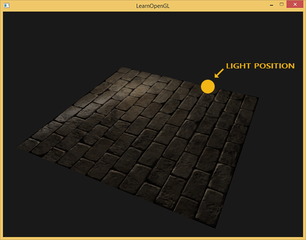
The lighting turned out to be completely wrong! And the reason is simple: the normal samples from the map all also return vectors oriented along the positive semi-axis oZ, although in this case they should be oriented in the direction of the positive semi-axis oY of the surface normal. At the same time, the calculation of illumination proceeds as if the surface normals are located as if the plane is still oriented towards the positive oZ semi-axis, which gives an incorrect result. The figure below more clearly shows the orientation of the surface normals read from the normal map:
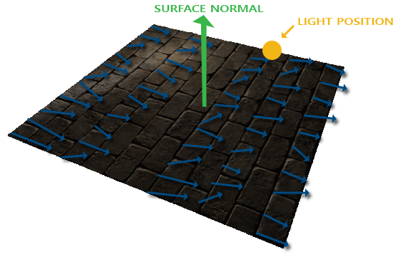
It can be seen that the normals are generally aligned along the oZ positive semiaxis, although they should be aligned along the normal to the surface, which is directed along the oY positive semiaxis.
A possible solution would be to specify a separate normal map for each orientation of the surface under consideration. For a cube, it would take six normal maps, and for more complex models the number of possible orientations may be too high and not suitable for implementation.
There is another, mathematically more complex approach, which proposes to carry out calculations of illumination in another coordinate system: such that the normal vectors in it always approximately coincide with the positive semi-axis oZ. Other vectors required for lighting calculations are then converted to this coordinate system. This method makes it possible to use one normal map for any orientation of the object. And this specific coordinate system is called tangent space or tangent space .
Tangent space
It should be noted that the normal vector in the normal map is expressed directly in the tangent space, i.e. in such a coordinate system that the normal is always directed approximately in the direction of the positive semi-axis oZ. The tangent space is defined as a coordinate system local to the plane of the triangle and each normal vector is defined within this coordinate system. It is possible to imagine this system as a local coordinate system for the normal map: all vectors in it are set directed towards the positive semi-axis oZ, regardless of the final orientation of the surface. Using specially prepared transformation matrices, one can transform the normal vectors from this local tangent coordinate system into world or species coordinates, orienting them in accordance with the final position of the surfaces subjected to texturing.
Consider the previous example with the incorrect application of normal mapping, where the plane was oriented along the positive semi-axis oY. Since the normal map is given in the tangent space, one of the correction options is the calculation of the matrix of the transition of the normals from the tangent space to such that they would become oriented along the normal to the surface. This would cause the normals to become aligned along the positive semiaxis oY. A remarkable property of the tangent space is the fact that by calculating such a matrix we can reorient the normals to any surface and its orientation.
Such a matrix is abbreviated as TBN , which is an abbreviation for the name of the triplet vectors Tangent , Bitangent, andNormal . We need to find these three vectors in order to form this basis change matrix. Such a matrix makes the transition of the vector from the tangent space to some other one, and for its formation, three mutually perpendicular vectors are needed, the orientation of which corresponds to the orientation of the plane of the normal map. This is a direction vector up, right and forward, a set familiar to us from the lesson about the virtual camera .
With the top all clear at once - this is our normal vector. The vector to the right and forward are called tangent ( tangent ) and bitwise ( bitangent ), respectively. The following figure gives an idea of their relative position on the plane:
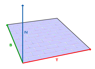
The calculation of the tangent and the bitmap is not as obvious as the calculation of the normal vector. In the figure, you can see that the direction of the tangent and bi-tangent normal map is aligned with the axes defining the surface texture coordinates. This fact is the basis for the calculation of these two vectors which will require some skill with mathematics. Look at the picture:
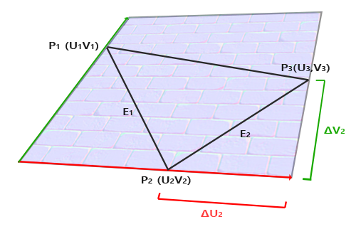
Changes to texture coordinates along a triangle face E 2 designated asΔ U 2 andΔ V 2 expressed in the same directions as the tangent vectorsT and bikasatelnoyBed and . Based on this fact, one can express the faces of a triangleE 1 andE 2 in the form of a linear combination of tangent and bi-tangent vectors:
E 1 = Δ U 1 T + Δ V 1 B
E 2 = Δ U 2 T + Δ V 2 B
Converting into element-wise recording we get:
( E 1 x , E 1 y , E 1 z ) = Δ U 1 ( T x , T y , T z ) + Δ V 1 ( B x , B y , B z )
( E 2 x , E 2 y , E 2 z ) = Δ U 2 ( T x , T y , T z ) + Δ V 2 ( B x , B y , B z )
E is calculated as the vector of the difference of two vectors, andΔ U andΔ V as the difference of texture coordinates. It remains to find two unknowns in two equations: the tangentT and bicantBed and . If you still remember the lessons of algebra, then you know that such conditions make it possible to solve the system forT and forBed and .
The latter form of equations allows us to rewrite it in the form of matrix multiplication:
[ E 1 x E 1 y E 1 z E 2 x E 2 y E 2 z ] = [ Δ U 1 Δ V 1 Δ U 2 Δ V 2 ] [ T x T y T z B x B y B z ]
Try to mentally perform a matrix multiplication to make sure the record is correct. Writing the system in matrix form makes it much easier to understand the approach to findingT and. Multiply both sides of the equation by the inverse:
We get a decision regarding and which, however, requires the calculation of the inverse matrix of changes in texture coordinates. We will not go into the details of calculating inverse matrices - the expression for the inverse matrix looks like the product of the number inverse to the determinant of the original matrix, and the adjoint matrix:
This expression is the formula for calculating the tangent vector and bikasatelnoy based on the coordinates of the faces of the triangle and the corresponding texture coordinates.
Do not worry if the essence of the above mathematical calculations eludes you. If you understand that we get the tangent and the binary on the basis of the coordinates of the triangle's vertices and their texture coordinates (since the texture coordinates also belong to the tangent space) - this is half the battle.
Calculation of tangents and bitangts
In the example of this lesson, we took a simple plane, looking in the direction of the positive semi-axis oZ. Now we will try to implement normal mapping using tangent space in order to be able to orient the plane in the example as we like, without destroying the effect of normal mapping. Using the above calculation, we will manually find the tangent and bicassive to the surface under consideration.
Let us assume that the plane is composed of the following vertices with texture coordinates (two triangles are given by vectors 1, 2, 3 and 1, 3, 4):
// координаты вершин
glm::vec3 pos1(-1.0,  1.0, 0.0);
glm::vec3 pos2(-1.0, -1.0, 0.0);
glm::vec3 pos3( 1.0, -1.0, 0.0);
glm::vec3 pos4( 1.0,  1.0, 0.0);
// текстурные координаты
glm::vec2 uv1(0.0, 1.0);
glm::vec2 uv2(0.0, 0.0);
glm::vec2 uv3(1.0, 0.0);
glm::vec2 uv4(1.0, 1.0);
// вектор нормали
glm::vec3 nm(0.0, 0.0, 1.0);
First, we calculate the vectors describing the faces of the triangle, as well as the deltas of the texture coordinates:
glm::vec3 edge1 = pos2 - pos1;
glm::vec3 edge2 = pos3 - pos1;
glm::vec2 deltaUV1 = uv2 - uv1;
glm::vec2 deltaUV2 = uv3 - uv1;
Having on hand the necessary initial data we can proceed to the calculation of the tangent and the bicant directly by the formulas from the previous section:
float f = 1.0f / (deltaUV1.x * deltaUV2.y - deltaUV2.x * deltaUV1.y);
tangent1.x = f * (deltaUV2.y * edge1.x - deltaUV1.y * edge2.x);
tangent1.y = f * (deltaUV2.y * edge1.y - deltaUV1.y * edge2.y);
tangent1.z = f * (deltaUV2.y * edge1.z - deltaUV1.y * edge2.z);
tangent1 = glm::normalize(tangent1);
bitangent1.x = f * (-deltaUV2.x * edge1.x + deltaUV1.x * edge2.x);
bitangent1.y = f * (-deltaUV2.x * edge1.y + deltaUV1.x * edge2.y);
bitangent1.z = f * (-deltaUV2.x * edge1.z + deltaUV1.x * edge2.z);
bitangent1 = glm::normalize(bitangent1);
[...] // аналогичный код для расчета касательных второго треугольника плоскости
First we put the fractional component of the final expression into a separate variable f . Then for each component of the vectors we perform the corresponding part of the matrix multiplication and multiply by f . By comparing this code with the final calculation formula, you can see that this is literally its arrangement. Do not forget to carry out normalization at the end so that the vectors found are single.
Since the triangle is a flat figure, it is enough to calculate the tangent and the cutout once per triangle - they will be the same for all vertices. It should be noted that most of the implementations of working with models (such as loaders or landscape generators) use such an organization of triangles, where they share vertices with other triangles. In such cases, developers usually resort to averaging the parameters in common vertices, such as the normal vector, tangent and biting, to get a smoother result. The triangles that make up our plane also share several vertices, but since both of them lie in the same plane, averaging is not required. Yet it is useful to remember that such an approach is available in real-world applications and tasks.
The resulting tangent and bi-vector vectors should have the values (1, 0, 0) and (0, 1, 0), respectively. That, together with the normal vector (0, 0, 1) form the orthogonal matrix TBN. If you visualize the resulting basis along with the plane, you get the following image:
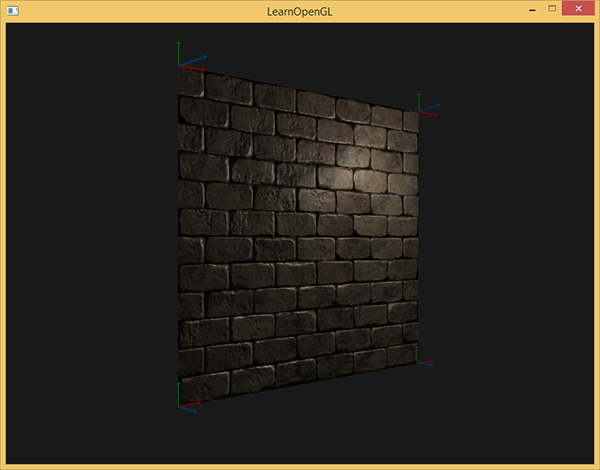
Now, having the calculated vectors, you can start the full implementation of normal mapping.
Normal mapping in tangent space
First you need to create a matrix TBN in shaders. For this purpose, we will transfer the previously prepared tangent and bitwise vectors to the vertex shader through the vertex attributes:
#version 330 core
layout (location = 0) in vec3 aPos;
layout (location = 1) in vec3 aNormal;
layout (location = 2) in vec2 aTexCoords;
layout (location = 3) in vec3 aTangent;
layout (location = 4) in vec3 aBitangent;
In the code of the vertex shader itself, we will form the matrix directly:
voidmain(){
   [...]
   vec3 T = normalize(vec3(model * vec4(aTangent,   0.0)));
   vec3 B = normalize(vec3(model * vec4(aBitangent, 0.0)));
   vec3 N = normalize(vec3(model * vec4(aNormal,    0.0)));
   mat3 TBN = mat3(T, B, N)
}
In the first code transform all vector basis of the tangent space coordinate system in which it is convenient to work - in this case, the world coordinate system, and we multiply a vector by a matrix model model . Next, we create the TBN matrix itself by simply passing all three relevant vectors to the mat3 constructor . Pay attention that for the complete correctness of the order of calculations, it is necessary to multiply the vectors not by the model matrix, but by the normal matrix, since we are only interested in the orientation of the vectors, but not in their displacement or scaling
Strictly speaking, it is not at all necessary to transmit a vector to a shader.
Since the triplet of TBN vectors are mutually perpendicular, the quicant can be trivially found in the shader through vector multiplication:vec3 B = cross(N, T)
So the TBN matrix is obtained, how do we use it? In fact, there are two approaches to its use in normal mapping:
- Use the TBN matrix to transform all the necessary vectors from the tangent space to the world one. Transfer the results to the fragment shader, where, also using the matrix, convert the vector from the normal map to the world space. As a result, the normal vector will be in the space where all the lighting is calculated.
- Take the matrix inverse to TBN and transform all the necessary vectors from world space to tangent. Those. use this matrix to convert vectors involved in lighting calculations into tangent space. The normal vector in this case also remains in the same space as the other participants in the calculation of the illumination.
Let's consider the first option. The normal vector from the corresponding texture is given in the tangent space, while the other vectors used in the calculation of the illumination are given in world space. By transferring the TBN matrix to the fragment shader, we could convert the normal vector obtained by sampling from the texture from the tangent space to the world space, ensuring the unity of the coordinate systems for all elements of the illumination calculation. In this case, all calculations (especially scalar multiplications of vectors) will be correct.
Transferring the TBN matrix is done in the simplest way:
out VS_OUT {
    vec3 FragPos;
    vec2 TexCoords;
    mat3 TBN;
} vs_out;
voidmain(){
    [...]
    vs_out.TBN = mat3(T, B, N);
}
In the code of the fragment shader, respectively, we set the input variable of the mat3 type:
in VS_OUT {
    vec3 FragPos;
    vec2 TexCoords;
    mat3 TBN;
} fs_in;
With the matrix in hand, you can specify the code for obtaining the normal by expressing the translation from the tangent into the world space:
normal = texture(normalMap, fs_in.TexCoords).rgb;
normal = normalize(normal * 2.0 - 1.0);
normal = normalize(fs_in.TBN * normal);
Since the resulting normal is now set in world space, there is no need to change anything else in the shader code. The illumination calculations assume the normal vector given in world coordinates.
Let's also look at the second approach. It will require obtaining the inverse TBN matrix, as well as transferring all the vectors involved in the illumination calculation from the world coordinate system to the one that corresponds to the normal vectors obtained from the texture - the tangent. In this case, the formation of the TBN matrix remains unchanged, but before transferring to the fragment shader, we need to get an inverse matrix:
vs_out.TBN = transpose(mat3(T, B, N)); Notice that the transpose () function is used instead of inverse () . Such a substitution is valid, since for orthogonal matrices (where all axes are represented by unit mutually perpendicular vectors), obtaining the inverse matrix gives the result identical to the transposition. And this is very opportunely, since, in the general case, the calculation of the inverse matrix is much more computationally expensive in comparison with transposition.
In the code of the fragment shader, we will not convert the normal vector, but instead convert from the world coordinate system to the tangent other important vectors, namely, lightDir and viewDir. This solution also brings all the elements of the calculations into a single coordinate system, this time the tangent.
voidmain(){
    vec3 normal = texture(normalMap, fs_in.TexCoords).rgb;
    normal = normalize(normal * 2.0 - 1.0);
    vec3 lightDir = fs_in.TBN * normalize(lightPos - fs_in.FragPos);
    vec3 viewDir  = fs_in.TBN * normalize(viewPos - fs_in.FragPos);
    [...]
}
The second approach seems to be more laborious and requires more matrix multiplications in the fragment shader (which greatly affects performance). Why did we even take it apart?
The fact is that transferring vectors from world coordinates to tangents provides an additional advantage: in fact, we can take out all the transformation code from the fragment to the vertex shader! This approach is working because lightPos and viewPos do not change from fragment to fragment, and the value of fs_in.FragPoswe can also convert to the tangent space in the vertex shader, the interpolated value at the input to the fragment shader will be quite correct. Thus, for the second approach there is no need to translate all these vectors into the tangent space in the code of the fragment shader, while the first requires it - the normal is unique for each fragment.
As a result, we move away from the transfer of the inverse matrix to the TBN to the fragment shader and instead give it the position vector of the vertex, the light source and the observer in the tangent space. So we will get rid of costly matrix multiplications in the fragment shader, which will be a significant optimization, because the vertex shader is executed much less frequently. It is this advantage that makes the second approach one of the preferred in most cases of use.
out VS_OUT {
    vec3 FragPos;
    vec2 TexCoords;
    vec3 TangentLightPos;
    vec3 TangentViewPos;
    vec3 TangentFragPos;
} vs_out;
uniform vec3 lightPos;
uniform vec3 viewPos;
[...]
voidmain(){
    [...]
    mat3 TBN = transpose(mat3(T, B, N));
    vs_out.TangentLightPos = TBN * lightPos;
    vs_out.TangentViewPos  = TBN * viewPos;
    vs_out.TangentFragPos  = TBN * vec3(model * vec4(aPos, 0.0));
In the fragment shader, we turn to the use of new input variables in the calculations of lighting in tangent space. Since the normals are conditionally given in this space, all calculations remain correct.
Now that all normal mapping calculations are performed in a tangent space, we can change the orientation of the test surface in the application as we want and the lighting will remain correct:
glm::mat4 model(1.0f);
model = glm::rotate(model, (float)glfwGetTime() * -10.0f, glm::normalize(glm::vec3(1.0, 0.0, 1.0)));
shader.setMat4("model", model);
RenderQuad();
Indeed, outwardly, everything looks as it should:
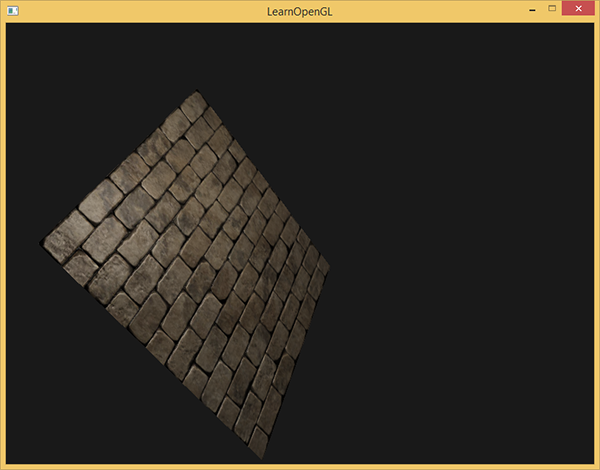
The sources are here .
Complex objects
So, we figured out how to perform a normal mapping in a tangent space and how to independently calculate the tangent and bi-tangent vectors for this. Fortunately, such a manual calculation is not something that often arises: for the most part, this code is implemented by developers somewhere in the depths of the model loader. In our case, this is true for the used Assimp loader .
Assimp provides a very useful options flag when loading models: aiProcess_CalcTangentSpace . When it is transferred to the ReadFile () function, the library itself will be engaged in calculating the smoothed tangents and bitmaps for each of the loaded vertices - a process similar to the one considered here.
const aiScene *scene = importer.ReadFile(
    path, aiProcess_Triangulate | aiProcess_FlipUVs | aiProcess_CalcTangentSpace
);
After that, you can directly access the calculated tangents:
vector.x = mesh->mTangents[i].x;
vector.y = mesh->mTangents[i].y;
vector.z = mesh->mTangents[i].z;
vertex.Tangent = vector;
You will also need to update the boot code so that it takes into account the receipt of normal maps for textured models. Wavefront Object format (.obj) exports normal maps in such a way that the Assimp aiTextureType_NORMAL flag does not ensure correct loading of these maps, while with the aiTextureType_HEIGHT flag everything works correctly. So personally, I usually load normal maps in the following way:
vector<Texture> normalMaps = loadMaterialTextures(material, aiTextureType_HEIGHT, "texture_normal"); Of course, for other model description formats and file types, this approach may not be appropriate. Also note that setting the aiProcess_CalcTangentSpace flag does not always work. We know that the calculation of tangents is based on texture coordinates, however, often the authors of the models apply various tricks to the texture coordinates, which breaks the calculation of tangents. Thus, mirror image of texture coordinates is often used for symmetrically textured models. If you do not take into account the fact of specularity, then the calculation of the tangents will be incorrect. Assimp does not do this accounting. The nanosuit model we are familiar with is not suitable for the demonstration, since it also uses mirroring.
But with a correctly textured model using normal and specular maps, the test application gives a very good result:
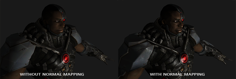
As you can see, the use of normal mapping gives a tangible increase in detail and is cheap in terms of cost performance.
Do not forget that the use of normal mapping can improve the performance for a particular scene. Without its use, the achievement of model detail is possible only through an increase in the density of the polygonal mesh, mesh. But this technique allows to achieve visually the same level of detail for low poly meshes. Below you can see a comparison of these two approaches:

The level of detail on the high-poly model and on the low-poly using normal mapping is almost indistinguishable. So this technique is an excellent method to replace high-poly models in a scene with simplified ones with almost no loss in visual quality.
Last note
There is one more technical detail regarding normal mapping, which slightly improves the quality at almost no additional cost.
When tangents are calculated for large and complex meshes that have a significant number of vertices belonging to several triangles, the tangent vectors are usually averaged to get a smooth and visually pleasing normal mapping result. However, this creates a problem: after averaging, a triplet of TBN vectors can lose mutual perpendicularity, which also means a loss of orthogonality for the TBN matrix. In the general case, the normal mapping result, obtained on the basis of a non-orthogonal matrix, is only slightly incorrect, but we can still improve it.
For this, it is enough to apply a simple mathematical method: the Gram-Schmidt processor re-orthogonalization of our triple vectors TBN. In the vertex shader code:
vec3 T = normalize(vec3(model * vec4(aTangent, 0.0)));
vec3 N = normalize(vec3(model * vec4(aNormal, 0.0)));
// ре-ортогонализация T относительно N
T = normalize(T - dot(T, N) * N);
// получаем перпендикулярный вектор B через векторное умножение T и N
vec3 B = cross(N, T);
mat3 TBN = mat3(T, B, N)
This, albeit small, amendment improves the quality of a normal mapping in exchange for a meager overhead. If you are interested in the details of this procedure, you can see the last part of the video Normal Mapping Mathematics, the link to which is given below.
Additional resources
- Tutorial 26: Normal Mapping : The ogldev Normal Mapping lesson .
- How Normal Mapping Works : A video tutorial explaining the basics of the Normal Mapping from TheBennyBox .
- Normal Mapping Mathematics : a movie related to the previous one, explaining the math used in the Normal Mapping method, also from TheBennyBox .
- Tutorial 13: Normal Mapping : another lesson from opengl-tutorial.org .
PS : We have a telegram-konf to coordinate transfers. If there is a serious desire to help with the translation, then you are welcome!


