February 12, 2012 at 18:40
Modernization of an industrial IR station, or how to do it initially. Part 1

As a master in repairing digital equipment and laptops, there was an urgent need for an Infrared (IR) soldering station, but since ready-made kits are prohibitively expensive in Ukraine, two options were brought up for discussion: 1) Collect from scratch 2) Collect from blocks. I chose the second option, since it is less time and money consuming, and on the same day I purchased the lower preheater of the AOYUE Int 883 boards . As for me, it’s cheap and cheerful, and in principle it’s the most for my tasks. But in the process, shortcomings and “bugs” were identified and a decision was made to eliminate and modernize.
There are a lot of photos under the cut, the purpose of the article is to show how complex devices can be connected to a PC in an easy way and automate the process.
Traffic! A lot of photo material!
Let's start with a review of the preheater itself.
AOYUE Int 883
I borrowed the initial description here , since, in principle, repeating the same thing also makes no sense.
The body is solid, made of non-thin metal (mainly iron, the front panel is aluminum, the reflectors are also aluminum), it does not bend, does not creak, the quality of processing and painting is good, bottom and side there are ventilation holes. Bottom four rubber legs, "clearance" - about 2 cm, i.e. he certainly will not heat the table. The mesh between the quartz heater and the working area is aluminum, with two transverse holding steel "strings" - this is bad, because it will bend and heave, as demonstrated in the work. There is a temperature regulator on the front, a socket for connecting external thermocouples and a power switch, on the back there is a power cord and a fuse.
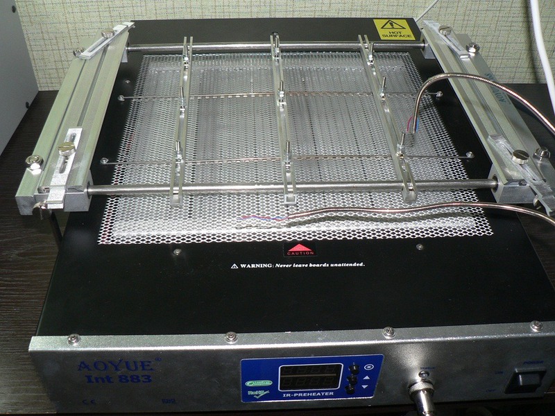
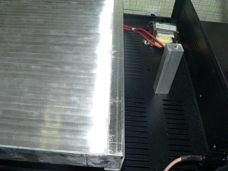
Next up is the heater. The heater is made of quartz tubes with a power of 1.5 kW (which is quite enough), the size of the heater is 260x295 (what is stated in the specifications is the grid field). This size is suitable for large boards, including full-sized desktops. The reflector is aluminum, it is mounted on aluminum brackets to the bottom of the heater, there is not much heat down and on the sides, the case only heats up a little.

The control is a PID controller with 3 operating modes and 3 thermocouples: internal on the heater and two external on the flexible hose.
0 mode allows you to set the temperature according to the internal sensor (400 maximum), while 2 external thermocouples can be used for monitoring (during operation, you can see their data).
1 mode sets the temperature in feedback with an external thermocouple, while the temperature sensor can be placed, say, on / under the board. The remaining sensors are monitoring.
2 mode - work on the thermal profile, the thermal profile is just one, but with 6 steps. Such a decision of the developers is not very clear - it would be better to make 2 thermal profiles in 3 steps. The maximum duration of each step is 200 seconds, the temperature is 250. That is, the total duration of the thermal profile can be 20 minutes, this is enough for all tasks.
I didn’t really like the work of PID, in general, for preheating purposes it’s quite suitable, but it could have been better. There are flaws in temperature control, for example, if you set a high heating rate, then “overshoot” occurs, possibly related to the inertia of the heaters (which is strange, it seems that quartz is better than ceramics in this regard, but at least with the simplest PID my station ceramics worked better).
External temperature sensors are made in the form of flexible metal hoses; an alloy wire sticks out from the end of the hose. On the one hand, it’s convenient, flexible hoses allow you to easily attach the sensor to the board, on the other hand, a flaw in the form of a protruding wire. I did not like the fact that the sensor socket in front, sometimes interfere.
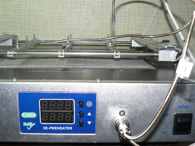
Initially, the thermostat showed the temperature in the "parrots". On the regulator board there are trimmers for each sensor. So calibration problems should not arise.
The quality of the soldering and mounting of the electronics is quite tolerable (for China), triacs (there are two of them, BTA20) are located on an aluminum radiator (thermal grease is present) over a large area, also blowed by a fan. Electronics is fenced off from the heater by an aluminum screen.
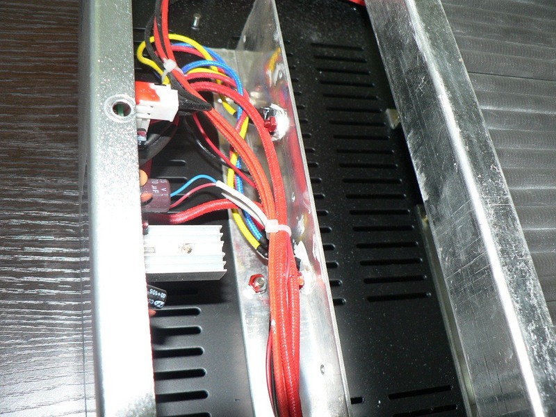
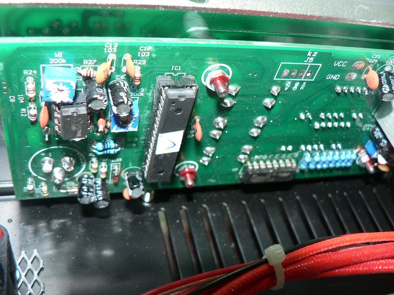
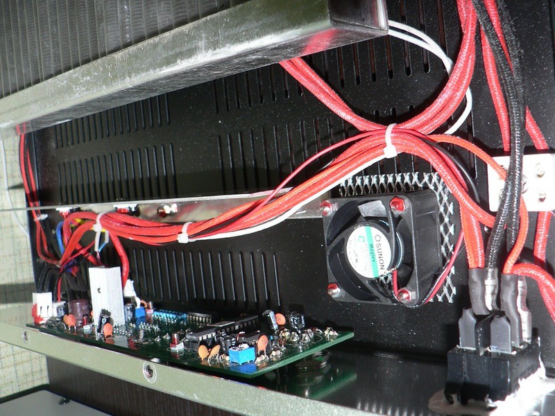
Table-holder boards. Actually, in addition to a large heating area, this is another advantage of the heater, as until I saw a single cheap heater with a decent board-holder table.
The table is made quite well, the workmanship does not cause any special problems, it is made simply and efficiently. In addition to the two main plates-dezhiteli, there are lower "supports" with bolts and nuts, preventing sagging of the board during heating, as well as 4 hooks from the main plates. The latter are convenient to use for mounting small boards, for example video cards. The design of the lower holders is not very convenient, but quite operational. Minus - the bolts are designed for openings of desktop boards, i.e. they will not climb into the openings of laptops. On the other hand, no one bothers putting the board directly on the bolts, or buying the right ones and changing them.

Deficiencies are identified by me personally. The board mounting table was originally sharpened for XBOX boards and needs further development. An attempt to calibrate the temperature sensors improved the situation a little, but it remains unpleasant in the extreme, it takes time to adjust the temperature and often chick the temperature sensors, which is critical because their position is lost and if the solder melts, you can tear off the details. In the built-in control bar, the function of recording thermal profiles was written
Formulation of the problem
1) A complete alteration of the control unit, namely: we throw out the old control unit in the trash, assemble our unit with the ability to monitor and control from the PC.
2) Assemble also a top-heating unit controlled by a PC
3) Achieve an ideal and normal temperature display
Implementation
Since time is short, and you need to work and use an IR station in addition to everything, interrupting its work for a critical time is not permissible, because I have chosen the simplest options.
1) On the breadboard, the control unit for the lower heater and the upper one was assembled, as well as data collection from the sensors and an interface for exchanging data with the PC.
2) Arduino bootloader is used as the filling of microcontrollers and quick debugging
3) As the control on the PC, the language Visual Basic .NET was chosen
Control unit, circuit, test (debug) option
Let's start with the diagram. Below is a diagram of a test block for debugging.
It consists of two microcontrollers Atmega8 and Atmega 168. The first MK acts as a USB converter - RSR232. The second MK will be the executive unit. So far, a simple thermistor has been soldered to test for debugging.

The final result
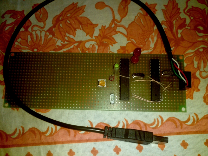
After the collect unit about MK need to flash the
firmware for Atmega8 and Fyuz
Firmware for Atmega 168 is taken from the folder with the Arduino the IDE arduino \-hardware \ arduino \ bootloaders \ atmega \ ATmegaBOOT_168_diecimila.hex
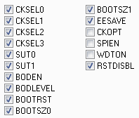
Fyuz for flashing LOW: 0xff HIGH: 0xdd
If there will be difficulties with the firmware, I will sign in more detail.
After assembly and firmware, our board should work perfectly in the Arduino IDE and it’s called “Arduino Diecimila or Duemilanove w / ATmega168” there.
If everything worked for you, then we will sew our test sketch for collecting thermocouple readings . We have finished the boards so far. And let's start writing PC software.
int temperatura;

void setup()

{

 Serial.begin(115200);

}

void loop()

{

 char ler = 'n';

 if(Serial.available()>0)

 {

 ler=Serial.read();

 }

 if(ler=='a')

 {

 delay(10);

 temperatura = analogRead(0);

 temperatura = (5* temperatura * 100)/1024;

 Serial.print(temperatura);

 }

}
Thermocouple Display Software
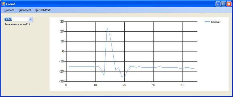
I wrote in Visual Studio 2010 in the language of Visual Basic .NET because it is easier for me. This program, when connected to the board, will display the thermocouple in the form of a graph (why? In the next part). It looks like this . At the moment, that's it. This is only an introductory part and all development will continue in the next part. I will be glad to answer any questions
Public Class Form1


Private Sub Form1_Load(ByVal sender As System.Object, ByVal e As System.EventArgs) Handles MyBase.Load

 Dim ports As String() = SerialPort1.GetPortNames()

 Dim port As String

 For Each port In ports

 ComboBox1.Items.Add(port)

 Next port

 End Sub


Private Sub ConnectToolStripMenuItem_Click(ByVal sender As System.Object, ByVal e As System.EventArgs) Handles ConnectToolStripMenuItem.Click

 SerialPort1.BaudRate = 115200

 SerialPort1.DataBits = 8

 SerialPort1.StopBits = IO.Ports.StopBits.One

 SerialPort1.Parity = IO.Ports.Parity.None

 SerialPort1.PortName = ComboBox1.Text

 Try

 SerialPort1.Open()

 Timer1.Start()


Catch ex As Exception


End Try

 End Sub


Private Sub DisconnectToolStripMenuItem_Click(ByVal sender As System.Object, ByVal e As System.EventArgs) Handles DisconnectToolStripMenuItem.Click

 Try

 Timer1.Stop()

 SerialPort1.Close()


Catch ex As Exception


End Try

 End Sub


Private Sub RefreshPortsToolStripMenuItem_Click(ByVal sender As System.Object, ByVal e As System.EventArgs) Handles RefreshPortsToolStripMenuItem.Click

 ComboBox1.Items.Clear()

 Dim ports As String() = SerialPort1.GetPortNames()

 Dim port As String

 For Each port In ports

 ComboBox1.Items.Add(port)

 Next port

 End Sub


Private Sub Timer1_Tick(ByVal sender As System.Object, ByVal e As System.EventArgs) Handles Timer1.Tick

 Try

 SerialPort1.Write("a")

 System.Threading.Thread.Sleep(250)

 Dim i As Integer = SerialPort1.ReadExisting

 Chart1.Series("Series1").Points.AddY(i)

 Label1.Text = "Temperatura actual" + i.ToString()

 Catch ex As Exception


End Try

 End Sub


Private Sub Chart1_Click(ByVal sender As System.Object, ByVal e As System.EventArgs) Handles Chart1.Click


End Sub

End Class