february 5, 2012 at 22:51
Model-oriented design, or continue taming the Cortex M3 with Matlab / Simulink
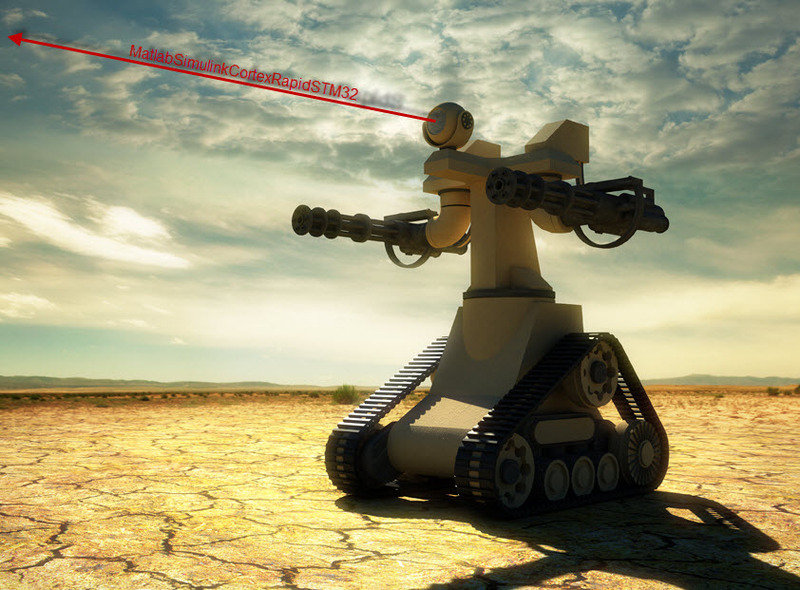
The image is taken, and slightly edited, from the blog of Anton Lopatin . Well, very inspiring.
Good afternoon, dear community!
In the last topic, I tried to make an introductory excursion into the model-oriented design of embedded systems using ARM microprocessors Cortex M3 and MATLAB / Simulink. We continue the dive, complicate the task. It is a pity the concept in the title illustration is still far away, but I will try to show the development process of one of its most important nodes, namely the turret homing system.
Below are quite a few images, but without them it’s boring and not clear.
Hardware
Unlike the first topic, we now have in our hands:
- FiO Std debug board from Thai friends from aimagin . Without it, working with the RapidSTM32 library for Simulink is slightly difficult. It is used both as a hardware key for rapidSTM32, and as a control module. On board has a stone STM32F103RET6.

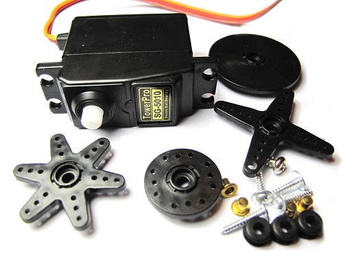
- 2 simple servo motors SG-5010
- WEB camera Logitech HD Webcam C270 . But not as glamorous as in the review and in the photo.

- A pair of resistors, wiring, connectors, a breadboard, a power supply from an old printer, rubber bands for a whatman paper, copper wire, a mini USB cable, a laptop, and, most importantly, a home-made soldering iron holder from the safety seat (made by Uncle Sasha, used as a bed) .
Another difference from the beautiful concept will be that for our crafts the concept of “assembled on the knee” is as close to reality as possible. A striking example of rapid development. Fast, cheap, efficient.
Statement of the problem and subtasks
The main task is to implement the functions of capturing and tracking the target. To achieve our goals, we have to:
- Establish a connection with the PC.
Our device will be recognized as HID, and will listen to my laptop via USB. - Mechanize homing head.
Stop flashing diodes, go to the servos. A classic of the genre of comprehending the wisdom of working with mechatronics. - Create a control system on the iron side.
Fur. component + HIL entails more complex control algorithms on the side of iron. At least the use of a PID controller. TAU is our everything! - Implement an algorithm for recognizing video and issuing control signals on the host side.
To track an object, you need to identify this object. For now, my laptop will do this, but in the future it will be possible to shift this task to ARM's strong shoulders. Here, it might be worth taking a closer look at the bigle board on the TI OMAP3530 processor. It's only the beginning.
Host Side Model
The collapsed model, which is assigned the functions of video processing and issuing control signals, looks like this: A
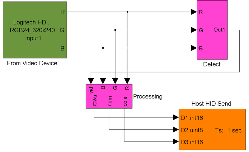
video signal divided into channels is transmitted to the detection and processing subsystems. After them, the output signals are transmitted via USB to the control board.
Suppose an object is highlighted by a laser with a certain wavelength. The main task of the video recognition subsystem will be the selection of a given color tone, filtering out possible interference and issuing a concise signal about the location of the object. For our "bull" we will use not a red scarf, but green, which again is not so important. You can also tie the movement here ...
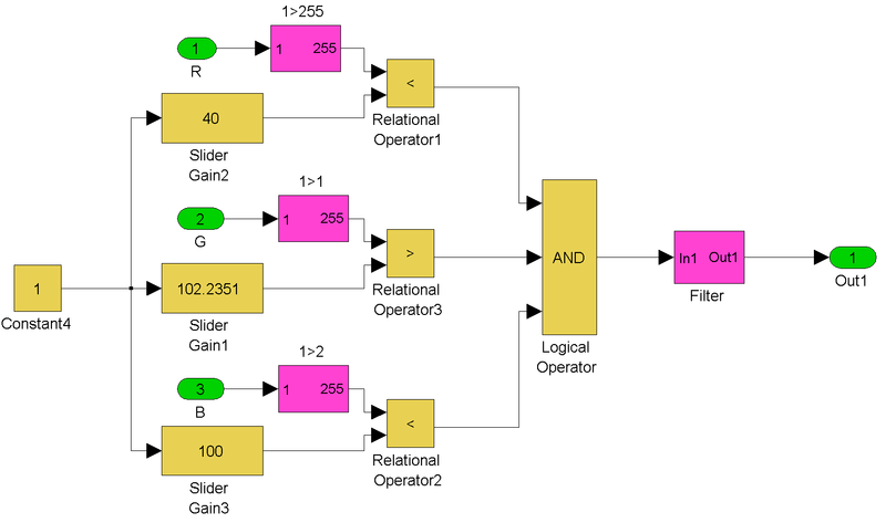
The detection subsystems look like this:
The filtering subsystems look like this

I got acquainted with video recognition during the development process, and therefore I chose the simplest algorithm. The split video signal passes through branches of the conditions that return true or false (instead of the RGB percentage) depending on the given conditions. As can be seen from the numerical values, I focused on the green color.
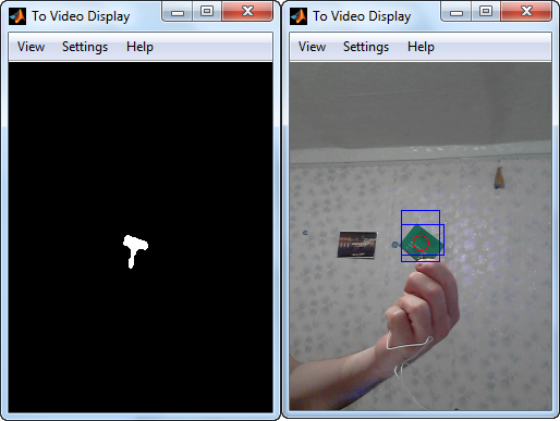
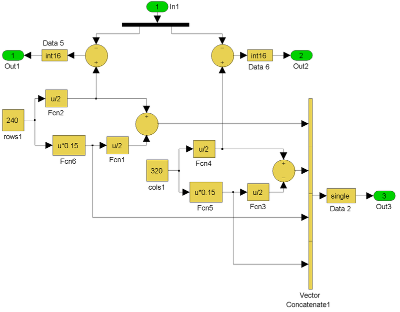
At the output of the systems, instead of the video, we get a matrix from the field of zeros and closed islands of units. The processing subsystem of the received information determines the areas and centers of the received "islands", outlines them with boundaries and equivalent circles, and also determines the distance of the center of the object from the center of the matrix. On the iron side, an error is transmitted with rows and columns for the largest island, and the number of islands. If this same num == 0, then the turret goes into standby mode and performs a horizontal horizontal scan of the terrain. Errors are not counted from the absolute center of the image, but from the borders of the rectangular “zero zone”. Inside this zone, the object is considered “captured” and the camera fixes its position. All additional constructions are adjusted to the original video, complementing the gray and gloomy
The subsystems for drawing additional graphics and error definitions look like this:

Simulink courteously and reminds us in advance that the branded blocks marked “Reglace” should be replaced before the release of the new version of the program. Otherwise, the model will not be compatible with it.
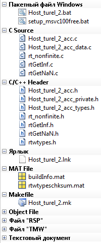
It should be noted that binding to running Simulink is optional. Using the same Simulink Coder, you can generate C ++ code to build a stand-alone application for both Windows and Linux. I am not strong at this yet, so I limited myself to the working Simulink model in Accelerator mode, that is, in partial compilation mode to increase execution speed:
Iron Side Model
The Simulink model from which the code for pouring into the microcontroller is generated looks as shown in the illustration below:
 Performed in a single clocking, which can be seen from the same color highlighting for all model blocks after the update. As mentioned earlier, in addition to elementary blocks such as addition or multiplication, the model contains two PID controllers. Rather, even PI, because the coefficient of the differentiating component is zero.
Parameters were selected manually empirically. But for more serious systems, MATLAB has a special Control System Toolbox for “tuning” linear control systems based on experimental data with the ability to set the required control parameters.
The small proportional coefficient and zero differential are due to a rather noticeable time delay in which each element of the system contributes.
The assignments of the Saturation and Dead Zone blocks, I think, are clear from the graphs on their icons.
Initially, the implementation of “standby” and “combat” modes was conceived using finite state machines, but then it turned out that the issue could be solved more simply. Therefore, FSM is yet to come. This concept is implemented inside Simulink with the help of the elegant Stateflow tool , and it is just as easily poured into the MK.
Generation, compilation and filling of the code is performed completely from under MATLAB. Keil doesn’t even need to run separately.
The development process itself
All of the above is for the most part already results rather than development stages.
While there was no serv (read the lack of hardware component as such), the system operation algorithms were worked out on such an ugly, monster-like draft model:
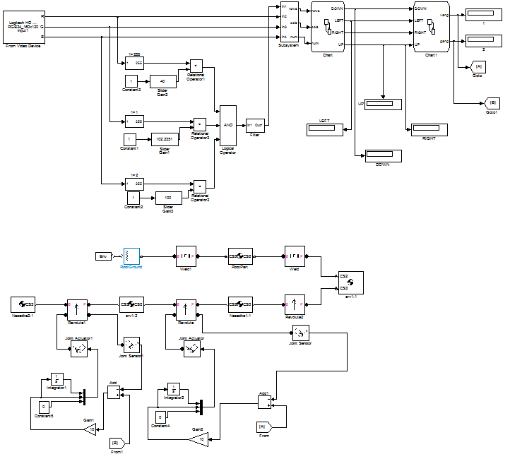
Then it became like this:

The main distinguishing part of these models is the mechanical subsystem (highlighted in blue in the previous illustration), which allowed evaluate the operation of the system exclusively using a PC. In my case, it was important to optimize the angular speed of rotation of the servos and the PI coefficients of the controllers, but a complete mechanical analysis of the system is also possible.
This is what the assembly looked like in Solidworks:
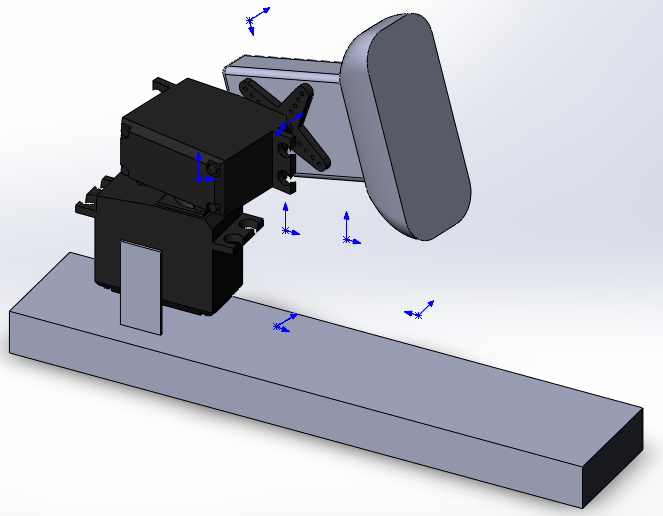
And it looks like the simulation of the assembly movement already inside the Simulink model:
There is a very serious tool for simulating dynamics and statics inside Solidworks, but I still work with MATLAB more closely. The assembly is exported using the SimMechanics Link utility. Here a lot of things have been written about her.
In a word, when the “iron” arrived, I already had almost everything ready. I simply deleted all unnecessary and divided the model into two components: Host and Target.
Test results
And finally, the video of the field test:
Yes, a pretty ugly build. For the prize of super direct hands, it certainly does not pretend.
The following is happening on the laptop screen:
conclusions
Positive:
- Development took a minimum of time and resources. Everything works satisfactorily and is easily upgradeable. Implementing a “trigger” is nothing easier. There are
100500more ports left on the board . You just need to add the condition branch when the center of the object is in the capture zone, which will feed the log. 1 to a specific port andlower the rail gun from the chain tosimulate a shot.
Instructive negative:
- Using the cat as a target failed. Gray camouflage is undetectable, and an attempt to attach a mark to it has failed. In addition, he is also terribly afraid of the buzz of serv. I had to experience everything on myself.
- To increase speed and stability, much more needs to be improved. The mechanical part was the most moody. Servo calibration took most of the time allotted for commissioning. With further development of the project, it will be necessary to switch to higher-quality devices, possibly with subsequent refinement and the introduction of their own feedback.
- I could not cope with the automatic change of the camera brightness settings depending on the lighting and the surrounding background. It is clear that this affected the selectivity of the recognition system. In the future, it is planned to use a separate camera module (possibly focusing on the IR range with the corresponding backlight) with a direct connection to the control board.
- With great pleasure and unlimited gratitude, I will take note of reasonable criticism in the comments. And I’ll add it here!
Updates:
UPD # 1 Project sources
MATLAB Models for Host & Target
Solidworks assembly
UPD # 2 Domestic manufacturer
Who is not a stranger to the patriotic idea (and who does not have Simmechanics in delivery), he can use domestic for mathematical modeling of mechanics before production (no less powerful) UM tool “Universal Mechanism” , which is successfully used by robots from MSTU. And not only them. Demos here .
He can speak with Simulink. For details, you can contact the haupraiser yupych .