November 15, 2011 at 22:51
Hifidiy A20. Assembling a power amplifier
- Tutorial
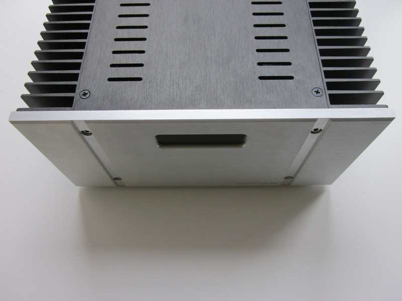
* Locally used stock photos, due to lack of their proper quality. Caution! There is a carpet on the photo, do not look at the carpet rugs :) A lot of big photos, traffic!
Greetings! As promised, I’ll talk about how I assembled a speaker for acoustics. Since industrial options did not suit me, I aimed my choice at diy options. The amplifier will be used with high-sensitivity shelving acoustics, I decided that I would assemble an amplifier with a power of 15-30 watts, be sure to in class A (Yes, yes, instead of a heater). He went through a lot of projects, settled on the clone Krell KSA 50 - HifiDIY A20. He completely arranged for me, with power, dimensions, components. And I set about assembling.
Some technical specifications:
Frequency range : 5-100K
Output power (At 8 Ohm load: 25 watts (In A class) 100 watts (In AB class).
Distortion: 0.01%
Dimensions (In centimeters): 25 * 13 * 32
Weight: 13kg
Purchase:
Everything is standard, ordered, paid, and after eighteen days received such beauty:
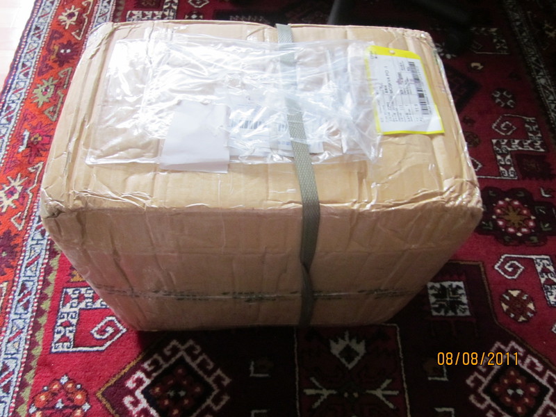
Fortunately, the packaging was excellent, not a scratch on the amplifier, and the box obviously played football, but everything was as usual.
Power Supply Assembly:
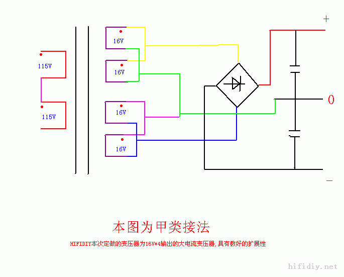
The power supply is made according to the standard scheme, the upc1237 chip is used as protection, it is it, because it requires a minimum of strapping and is quite reliable. The total filter capacity is 88,000 mKf. The transformer is universal, two primary units of 110, for our networks, must be connected in series, and four secondary units of 16 volts by 6 amperes.
So connect the windings:
And more clearly:
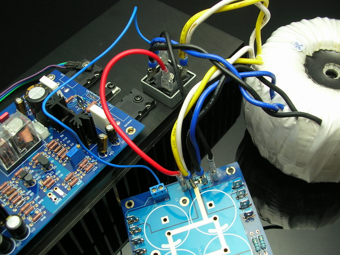
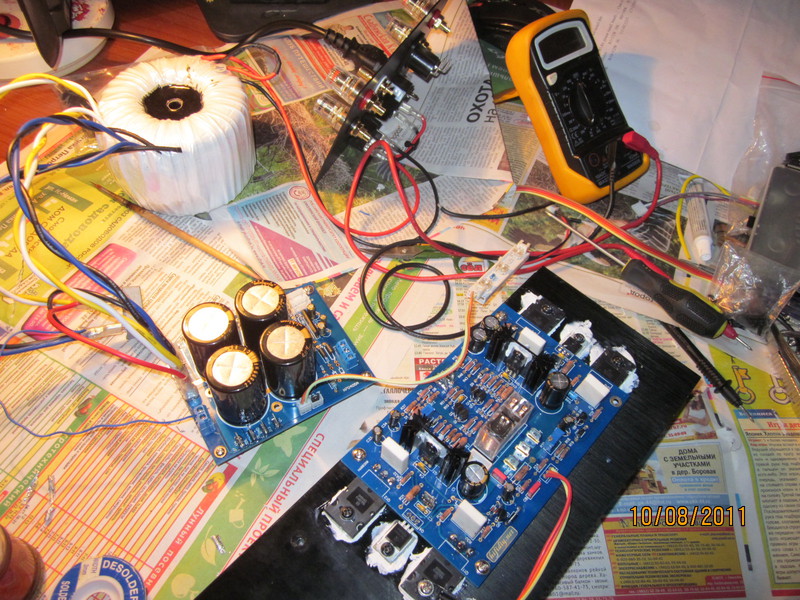
It all started, right away, it couldn’t be otherwise :) We are starting to collect the gain cards. I plan to put a soft start in the near future, since when charging the capacities, the power supply operates in an almost short circuit.
Amplifier assembly:
The amplifier is assembled on fairly high quality components, nichicon muse capacitors, 1% dale resistors, omron relays.
Everything goes according to the usual principle, from small to large, for a start we will prepare the board and form the conclusions of the resistors

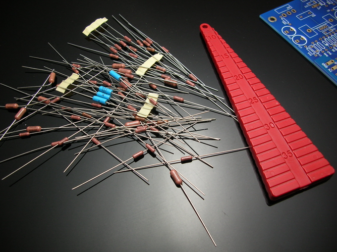

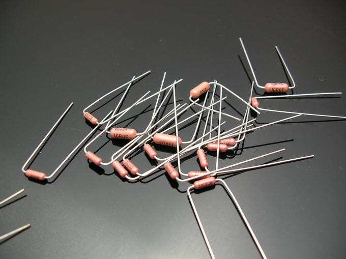
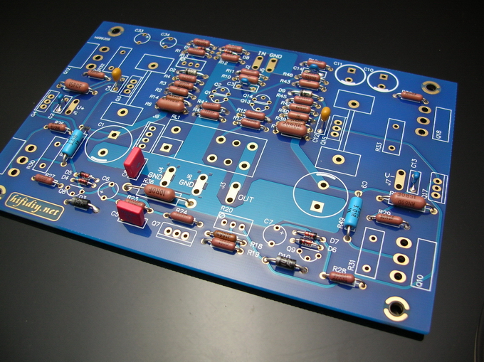
Soldered resistors, soldered capacitors, diodes (do not confuse the direction of inclusion) and zener diodes (also do not confuse :))
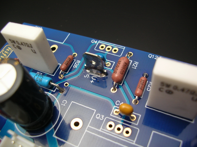
Now capacitors and resistors of emitters of output transistors

The power terminals must be soldered from both sides, that is, there is a risk of tearing, the terminals are put on tightly.
Now the missing transistors, relays, variable resistors.

Now we put the thermal stabilization transistor, mounted on the output.
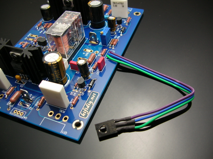
I won’t write about the preamplifier, although there is a version with it, but I have a clean source and I did not collect it.
We prepare the radiator, you can degrease and wipe with alcohol, we screw the racks.
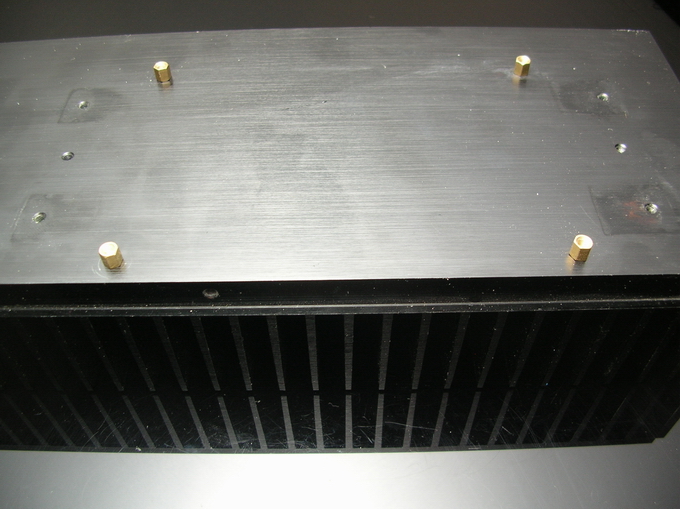
Fitting:

Do not forget about bushings and substrates:
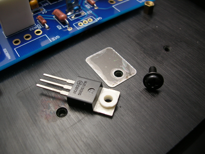
Now we install the output transistors, also do not forget about the substrate, the bushings are no longer needed.

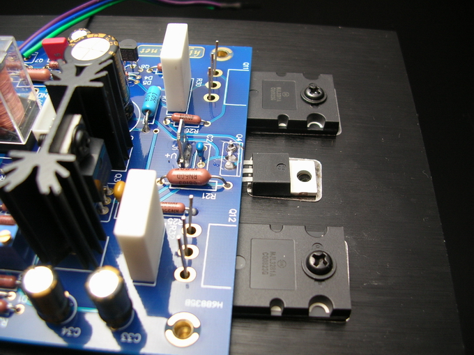
Do not forget to fix the thermal stabilization transistor and diode bridge:

The preparation for the test run went through, assembled, turned on, there was no noise, no crunch, crack, hmm, a couple of seconds later the smoke started with v +, I was very lucky that the flux burned out and not a piece of the track on the board. I checked everything probably five times, I can’t find the error, with a bad mood I postponed the assembly the next day. Then in the morning it dawned on me, it would be necessary to check the outputs, if npn was confused with pnp, as it turned out, it was a shame, but what to do, redid and the amplifier immediately wound up. Hurrah!
Ready boards :)
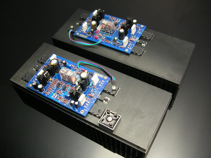
Now you need to turn on the design and set the quiescent current and zero at the output, set zero, then the quiescent current: I have 500 mA per transistor, 2A per channel, maybe more, but at room temperature +23 degrees, the case heats up to 50-60 degrees and this is not the limit :) The quiescent current is set on the resistor R20, the value is measured between d6 and q10. First you need to set a lower value than you need, with the structure warming up, the quiescent current creeps up, you need to warm up the amplifier to operating temperature for half an hour or an hour, and only then set the current, after you set the current, set zero at the output, it is regulated on the resistor R13 , and the current value is measured between r21 and j4. That's all, the setup is complete, it's time to put the amplifier in the case.
Putting the case:
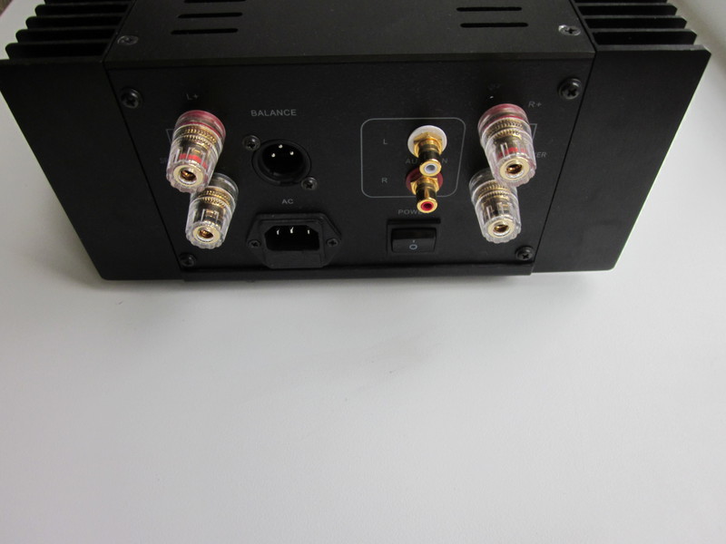
To begin with, we will assemble the back panel, I did not connect xlr, but the amplifier can be used with a balanced connection, only two amplifiers are needed, one per channel. I liked the switch very much, it immediately opens the phase and zero, it is very convenient so that you don’t grab hold of anything by chance during assembly.

We fasten the legs to the chassis and put the power supply:

We begin to assemble the chassis, the layout is VERY tight, it turned out that at the end of the assembly I did all the operations with tweezers.
It turned out like this:
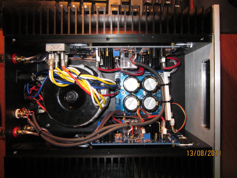
I removed power wires as far as possible from the signal ones, used a shielded wire, a 2.5 square mm cable goes to the output terminals, which is enough, in general. There was no mount to illuminate the indicator, I just attached it with ties to the signal. The glass with the logo was glued with superglue. The wire to the output connectors is soldered very tight, I even had a 70-watt soldering station stick :) So you need an old-fashioned tinker for buckets :)
Summary:
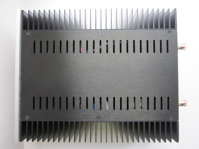
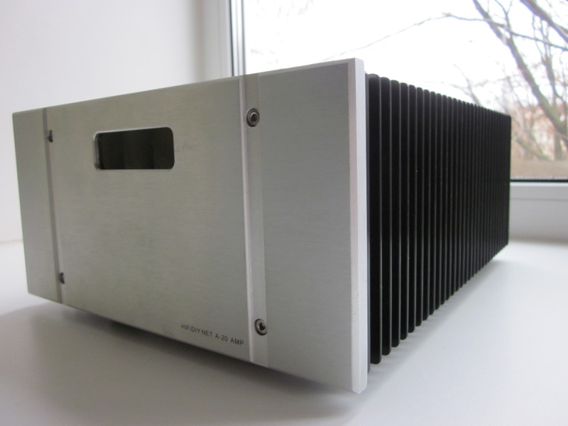
The amplifier turned out to be not big but heavy, but with an excellent sound, it will delight me with its sound on cold evenings, 360 watts of heat dissipate on the case, after all :)
Schemes:
1. Amplifier
2. Power supply
Revision Ideas
- - In the OOS circuit there are 2 polar electrolytes connected by pluses, replace them with a high-quality non-polar electrolyte (Something like Nichicon ES)
- - Replace current sources for input diffascades - on 2 resistors and a zener diode - with something on a transistor.
- - Add soft start.
Finished product
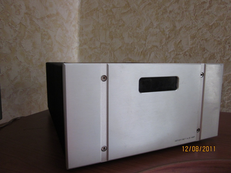
Thanks for attention! I will answer any questions in the comments.