Dramophone: portable digital drum kit
Good afternoon, dear Khabrovites. While the next article about STM32F microcontrollers is in the process of writing, I decided to share with you my old project, which was assembled on AVRs. Honestly, I was not too attracted to return to the topic of AVR, but because I recently excavated old materials on my projects, I decided that it would be better to share them with the public. The project is very simple, and the result, in my opinion, is quite interesting, which makes this device a good start for beginners. In general, if anyone wants to repeat - welcome to the cut, we begin to make a digital portable drum kit.
The name for the device turned out to be quite loud, but in fact it is just a fun toy. Although, we several times used it with friends as drummers while playing the guitar.
What are we collecting? We assemble a device that has 8 touch buttons, by clicking on which it plays a recorded sample of a percussion instrument.
This is how the complete device looks:

And this is how it works (on a video drum before being placed in the case).
Structurally, the device consists of the drama recorder board itself, on which the control controller, mikruha flash memory, an SD card slot, a 12-bit DAC and amplifier, a sensor board connected to the main board with a loop cable (SPI interface) and speaker are located. All this electronics is assembled in a case from the old Genius speaker, which fit perfectly.

In general, I advise you to take up this business - if you are assembling a device that should output a more or less loud sound, and you think in which case to shove it - look at the old speakers, it is quite possible they will suit you.
There was also a display in my circuit, but in addition to the test message, I did not begin to display anything on it, so we neglect it.
How to assemble a touch keyboard, I already told in the appropriatearticle . We will turn to the circuitry of the main board.
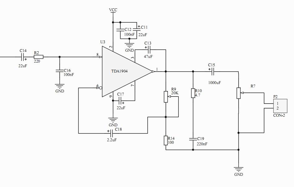
The device layout is very simple. The four-watt amplifier is assembled on a TDA1904 chip, fully according to the scheme recommended in the datasheet. We cut off the unnecessary constant component of the voltage by the capacitor C14, the low-pass filter on R2 and C16 restores the waveform after the DAC (the so-called interpolating filter).
The digital part consists of an ATMega32 microcontroller, an AT25FD161 flash memory chip, an SD card, and a 12-bit DAC7611 DAC. All peripherals, including an external touch keyboard, are connected via the SPI bus.
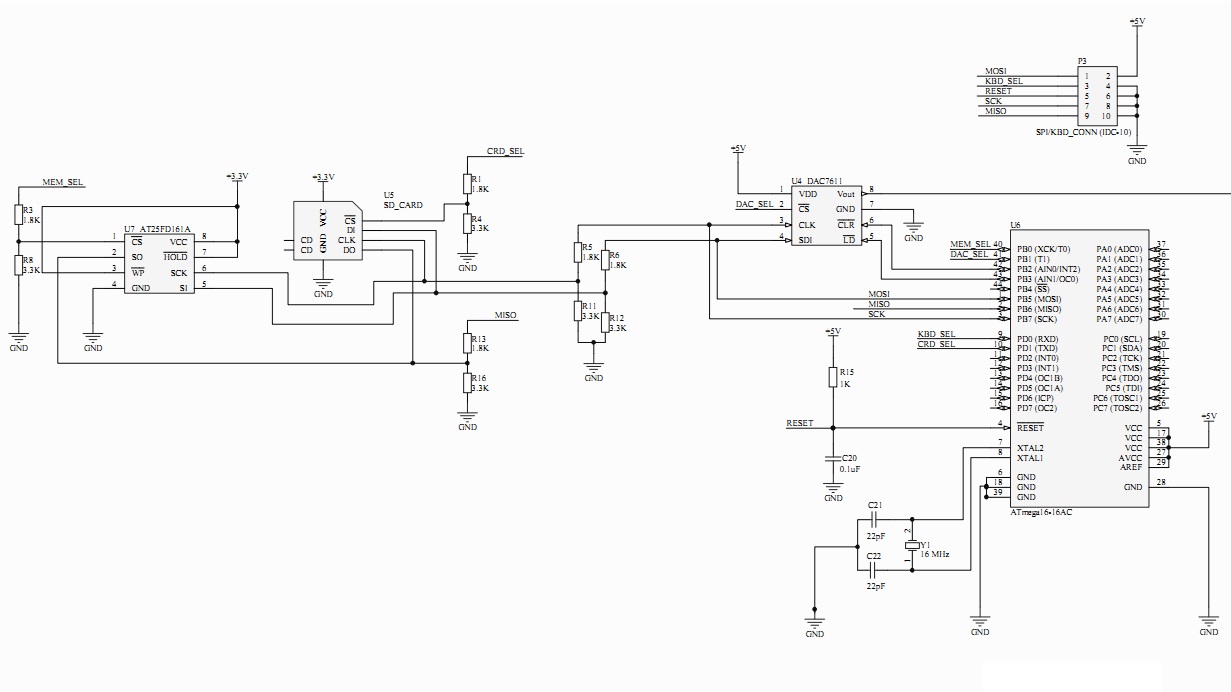
Since the project is old, one of my first, I can not say that the choice of components is ideal. Initially, the plans were Napoleonic, so he took the “bigger” mega and stuck the display - in fact, in the form in which it is now assembled, ATMega88 is enough. Since mega and DAC are powered by 5V, and the card and flash drive require 3.3, the levels are consistent with the dividers. This is not a good solution, I wouldn’t do it now, but would use a special converter so as not to overwhelm the signal fronts (and best of all, I would build the entire circuitry on 3.3V elements), but this is now)
As for the SD card, with connecting it, I used the information on the following site :
I must say, it has a large number of interesting projects and useful documentation, if you started working with ABP, be sure to look there.
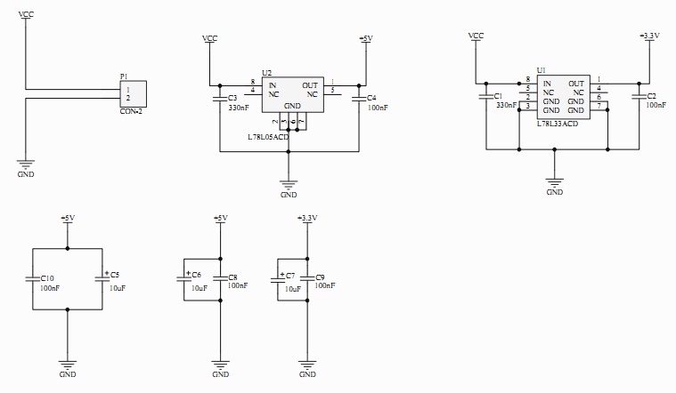
The device is powered by a 9V battery, the amplifier is powered directly from it, and the digital circuitry is via linear stabilizers at 3.3 and 5V.
That, in principle, is all that relates to the circuitry part. Since the project is more than two years old, it could well have missed something, or the scheme could have turned out to be an older version of what I have assembled in hardware, but I conveyed the main idea. It will not be difficult for you if you want to repeat and improve what I proposed.
How does it all work?
If we omit the question of how I originally conceived this (display, etc., huh), we get the following: I did not directly play samples from the card, because I was afraid that there would not be enough time to read the data (the SDI SPI mode is rather slow), so I used the card to transfer the samples to the USB flash drive, once, after which I disconnected it from the device and did not connect it again.
The device polls the SPI keyboard every few milliseconds, receives data from it, finds out which buttons are clamped. Since he does not have “polyphony”, priority is given to the last pressed one. After that, the timer starts, and with a sampling frequency of 16 KHz, the corresponding button for the sample starts to be read from the flash drive and issued to the DAC.
Program principles for working with the card are set out on the already mentioned site. In short - the card can work in two modes: SPI and standard. By default, standard mode is enabled, and by SPI it can only accept one command - switch the mode. The standard mode does not impose additional restrictions on speed, allows you to use a bus of 4 conductors, instead of one, but requires a CRC count, which without a hardware calculator will make this mode on a mega even slower than SPI. Therefore, the card is given a command to change modes (in this command, the CRC is checked, but it can be calculated in advance and output with hardcodes), after which you can communicate with it with the same commands, but without CRC, standard SPI signals. The library for working with the card can be found here.. Again, who is involved in AVR - add this link to your favorites, this is a huge library, which includes peripheral drivers (cards, displays, etc.), protocol implementations and much more. In order not to waste energy on the file system, samples encoded in 16 bits x 16 KHz were added raw, starting with the first byte of the card. This is easily done with WinHEX , an excellent hex editor that allows low-level recording on physical media. In the same form, the samples are overwritten on the flash memory chip. For convenience, the duration of all samples is the same and amounts to 8000 samples (half a second at a sampling frequency of 16KHz)
Working with a DAC and a flash drive is also easy: the DAC just needs to send 12 bits of data, the most significant bit forward, and then jump to the LD pin, which means a transfer from the input register to the internal one. Since mega works with bytes, you should add 12 bits to 16 zeros.
A flash drive accepts read, erase, and write commands. After the read / write commands, data can be received / returned by the stream, as the address counter in it is auto incremented.
I would be happy to share the program code with you, as I usually do, but alas - the source code was lost during the formatting of the hard disk, apparently, I overlooked it and didn’t save it ... But, I think it’s not difficult for you to set a timer at 16 KHz and issue an interrupt on the DAC, the value read from the flash drive)
I must say that it’s rather funny after a few years to write an article about my old projects developed during the training. Every now and then there are thoughts: “eh, what am I doing, because it could have been done differently, it would have been better!” Not to mention the fact that the element base also does not stand still and when developing a similar device on the same STM32F1xx, it will be possible to not worry about either an external DAC (there is a built-in one!) Or coordination of levels (powered from 3.3V, like a card ), nor about communication with the card (STMka can communicate with them in normal mode, with CRC). However, whatever this project was, it served as an excellent training in the development of devices. Therefore, I recommend to all beginners: after you master the flashing LEDs, choose a project that will be of interest to you and try to implement it. Any - at least the drum I described at least one of the hundreds of other AVR projects covered on the Internet, and even better, is completely your own. Let it ultimately turn out to be not what it was originally conceived, and later it will seem simple and crooked to you - but it will give you a very useful experience.
Good luck in the development!
PS
Links from the article:
Introduction
The name for the device turned out to be quite loud, but in fact it is just a fun toy. Although, we several times used it with friends as drummers while playing the guitar.
What are we collecting? We assemble a device that has 8 touch buttons, by clicking on which it plays a recorded sample of a percussion instrument.
This is how the complete device looks:
And this is how it works (on a video drum before being placed in the case).
Structurally, the device consists of the drama recorder board itself, on which the control controller, mikruha flash memory, an SD card slot, a 12-bit DAC and amplifier, a sensor board connected to the main board with a loop cable (SPI interface) and speaker are located. All this electronics is assembled in a case from the old Genius speaker, which fit perfectly.
In general, I advise you to take up this business - if you are assembling a device that should output a more or less loud sound, and you think in which case to shove it - look at the old speakers, it is quite possible they will suit you.
There was also a display in my circuit, but in addition to the test message, I did not begin to display anything on it, so we neglect it.
How to assemble a touch keyboard, I already told in the appropriatearticle . We will turn to the circuitry of the main board.
Circuitry
The device layout is very simple. The four-watt amplifier is assembled on a TDA1904 chip, fully according to the scheme recommended in the datasheet. We cut off the unnecessary constant component of the voltage by the capacitor C14, the low-pass filter on R2 and C16 restores the waveform after the DAC (the so-called interpolating filter).
The digital part consists of an ATMega32 microcontroller, an AT25FD161 flash memory chip, an SD card, and a 12-bit DAC7611 DAC. All peripherals, including an external touch keyboard, are connected via the SPI bus.
Since the project is old, one of my first, I can not say that the choice of components is ideal. Initially, the plans were Napoleonic, so he took the “bigger” mega and stuck the display - in fact, in the form in which it is now assembled, ATMega88 is enough. Since mega and DAC are powered by 5V, and the card and flash drive require 3.3, the levels are consistent with the dividers. This is not a good solution, I wouldn’t do it now, but would use a special converter so as not to overwhelm the signal fronts (and best of all, I would build the entire circuitry on 3.3V elements), but this is now)
As for the SD card, with connecting it, I used the information on the following site :
I must say, it has a large number of interesting projects and useful documentation, if you started working with ABP, be sure to look there.
The device is powered by a 9V battery, the amplifier is powered directly from it, and the digital circuitry is via linear stabilizers at 3.3 and 5V.
That, in principle, is all that relates to the circuitry part. Since the project is more than two years old, it could well have missed something, or the scheme could have turned out to be an older version of what I have assembled in hardware, but I conveyed the main idea. It will not be difficult for you if you want to repeat and improve what I proposed.
Software implementation
How does it all work?
If we omit the question of how I originally conceived this (display, etc., huh), we get the following: I did not directly play samples from the card, because I was afraid that there would not be enough time to read the data (the SDI SPI mode is rather slow), so I used the card to transfer the samples to the USB flash drive, once, after which I disconnected it from the device and did not connect it again.
The device polls the SPI keyboard every few milliseconds, receives data from it, finds out which buttons are clamped. Since he does not have “polyphony”, priority is given to the last pressed one. After that, the timer starts, and with a sampling frequency of 16 KHz, the corresponding button for the sample starts to be read from the flash drive and issued to the DAC.
Program principles for working with the card are set out on the already mentioned site. In short - the card can work in two modes: SPI and standard. By default, standard mode is enabled, and by SPI it can only accept one command - switch the mode. The standard mode does not impose additional restrictions on speed, allows you to use a bus of 4 conductors, instead of one, but requires a CRC count, which without a hardware calculator will make this mode on a mega even slower than SPI. Therefore, the card is given a command to change modes (in this command, the CRC is checked, but it can be calculated in advance and output with hardcodes), after which you can communicate with it with the same commands, but without CRC, standard SPI signals. The library for working with the card can be found here.. Again, who is involved in AVR - add this link to your favorites, this is a huge library, which includes peripheral drivers (cards, displays, etc.), protocol implementations and much more. In order not to waste energy on the file system, samples encoded in 16 bits x 16 KHz were added raw, starting with the first byte of the card. This is easily done with WinHEX , an excellent hex editor that allows low-level recording on physical media. In the same form, the samples are overwritten on the flash memory chip. For convenience, the duration of all samples is the same and amounts to 8000 samples (half a second at a sampling frequency of 16KHz)
Working with a DAC and a flash drive is also easy: the DAC just needs to send 12 bits of data, the most significant bit forward, and then jump to the LD pin, which means a transfer from the input register to the internal one. Since mega works with bytes, you should add 12 bits to 16 zeros.
A flash drive accepts read, erase, and write commands. After the read / write commands, data can be received / returned by the stream, as the address counter in it is auto incremented.
I would be happy to share the program code with you, as I usually do, but alas - the source code was lost during the formatting of the hard disk, apparently, I overlooked it and didn’t save it ... But, I think it’s not difficult for you to set a timer at 16 KHz and issue an interrupt on the DAC, the value read from the flash drive)
Conclusion
I must say that it’s rather funny after a few years to write an article about my old projects developed during the training. Every now and then there are thoughts: “eh, what am I doing, because it could have been done differently, it would have been better!” Not to mention the fact that the element base also does not stand still and when developing a similar device on the same STM32F1xx, it will be possible to not worry about either an external DAC (there is a built-in one!) Or coordination of levels (powered from 3.3V, like a card ), nor about communication with the card (STMka can communicate with them in normal mode, with CRC). However, whatever this project was, it served as an excellent training in the development of devices. Therefore, I recommend to all beginners: after you master the flashing LEDs, choose a project that will be of interest to you and try to implement it. Any - at least the drum I described at least one of the hundreds of other AVR projects covered on the Internet, and even better, is completely your own. Let it ultimately turn out to be not what it was originally conceived, and later it will seem simple and crooked to you - but it will give you a very useful experience.
Good luck in the development!
PS
Links from the article:
- The site of a certain device developer on ABP, many projects and useful information - in particular - the use of SD cards: http://elm-chan.org/docs/mmc/mmc_e.html
- A huge library of peripheral drivers and other goodies for AVR: http://www.procyonengineering.com/embedded/avr/avrlib/
- Information on the WinHEX hex editor on the wiki: http://en.wikipedia.org/wiki/WinHex
- Datasheet on TDA1904, which shows a typical connection diagram and describes the purpose of all the details: http://www.datasheetcatalog.org/datasheet/stmicroelectronics/1445.pdf