Plasma Singing: Foggy Perspectives of Ionophones
Today the most common type of sound emitters in acoustic systems is a dynamic loudspeaker. Isodynamic and electrostatic drivers are even more rarely used. Many are convinced that the speakers, as a type of loudspeaker, have exhausted the resource of development, and the evolution of acoustic systems should go the other way.
It is known that the electromechanical principle of sound reproduction is far from perfect, which is associated with the appearance of parasitic overtones, resonances and distortions. At the same time, psychoacoustic studies of such scientists as Fletcher, Linkdeier, Aldoshina demonstrate that the average human hearing is susceptible to seemingly insignificant changes in loudness (0.2-0.3 dB), timbre, can determine short delays between signals (12 -15 µs). For this reason, a number of enthusiasts believe that the future of sound emitters, at least, RF drivers for ionophones.
At the moment, the plasma emitter (ionophone) remains exotic for a few audiophiles, as well as radio amateurs who experiment with the creation of twitter of this type. In this article I will introduce (those who are not familiar with) the principle of operation of such emitters, pay attention to the history of “singing arcs”, describe the advantages and disadvantages, talk about independent and serial development of ionophones, and share my thoughts about the prospects for mass use of such emitters in audio equipment.
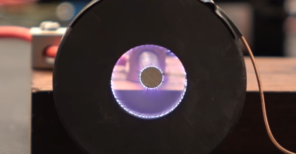
The principle of the ionophone is as follows: the source of sound waves is the gap between the electrodes, in which an electric arc occurs when an alternating current of high voltage is applied (about 10 kV to 15 kV), with a frequency of about 20-30 MHz. During playback, the discharge current is modulated by an audio signal, due to which a change in the volume of ionized air between the electrodes occurs — sound waves are formed.
It looks like this.
In fact, an ionophone creates a sound like a lightning strike, but unlike the latter, this process can be controlled.
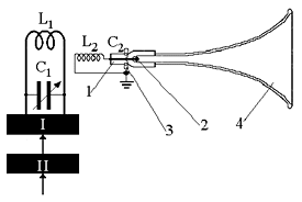
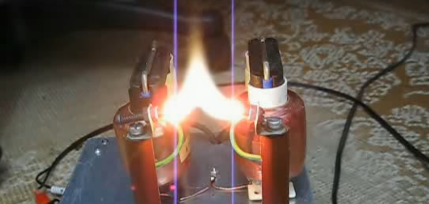
There are two types of ionophones, which differ in the localization of the occurrence of discharges. The first involves the appearance of a corona discharge of about one electron. In the second, an arc forming a sound wave arises between two electrodes. The corona type is common in the industrial production of ionophones, the arc type is more often used in enthusiast experiments and artisanal production. To increase the efficiency of sound radiation, as a rule, horn acoustic design of emitters is used.
An important feature of ionophones is that they are used most often to reproduce the high-frequency spectrum. When reproducing medium and low frequencies, it is necessary to increase the gap between the electrodes, therefore, to further increase the voltage.
In 1900, the British physicist and inventor William Daddel (Duddel) was the first to demonstrate controlled extraction of sounds from an electric arc. Daddel used the piano keyboard to control the power supply. The invention received the loud name "Singing Arc", and is now recognized as one of the first prototypes of the synthesizer. The gadget impressed his contemporaries physics, but did not receive development.

A specialized sound transmitter based on this principle was proposed in 1946 by Siegfried Klein. He bounded the arc, placing it in a small quartz tube that connected to a horn. A corona discharge in a Klein radiator is created between the anode (located in a quartz tube) and the cathode (metal cylinder) in which the anode tube was placed.
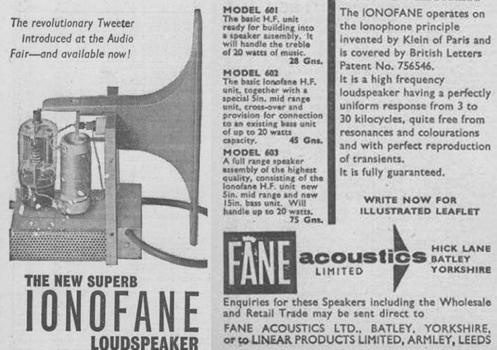
When a voltage of 10 kV (with a frequency of 100 kHz) modulated by an audio signal was applied to the electrodes, a cloud of ionized air arose around the anode, which, when compressed and expanded (as a result of modulation), formed a sound wave. The temperature appearing in the corona discharge region reached 1700 ° C - this significantly reduced the survivability of the electrodes. To increase the practicality of the emitters, Klein tried to use platinum and other metals. Later, a special alloy of chromium, aluminum and iron appeared, thanks to which the problem of the thermal stability of the electrodes was solved. Not the smaller problem of the Siegfried Klein ionophone was the characteristic whistle accompanying the appearance of a corona discharge. The unwanted sound was eliminated by repeatedly increasing the generator frequency (up to 20 MHz).
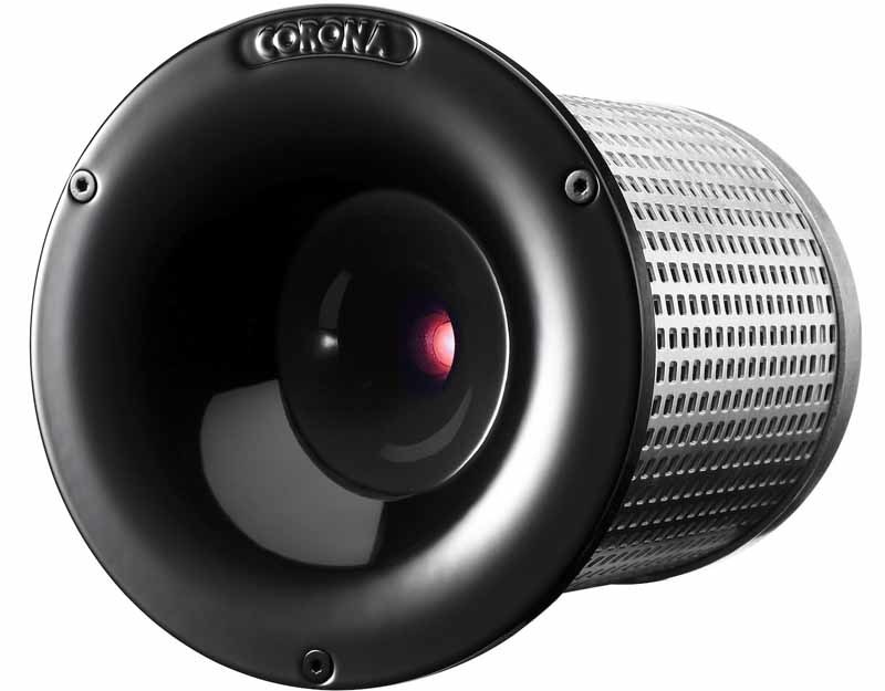
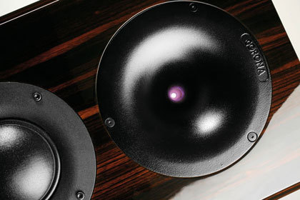
During the second half of the last century, attempts to serially release ionophones were made by such companies as Plessely, Telefunken, Magnat, Audax, Fane Acoustics. The most successful developments in the creation of ionophones are serial tweeters of Lansche Audio, Acapella and our compatriots Viger-Audio. In particular, Lansche Audio patented the corona emitter used by them, which is sold under the commercial name CORONA.
The principle of the ionophone is acoustically attractive due to the absence of moving parts and the membrane. This allows you to get rid of transient distortion, problems with resonances and other troubles characteristic of electromechanical emitters. Theoretically, ionophones should not distort the sound, and the frequency response of these emitters is absolutely uniform. Ionophones tests demonstrate an extremely low level of distortion, unattainable for other types of emitters, and are also capable of reproducing high frequencies far beyond the limits of human hearing (up to 150 kHz).

With all the advantages, ionophones are not (and possibly in the future) widespread. The reason is a number of shortcomings of devices of this type. The main problem is the safety of drivers, because To create an arc, a high voltage current is required. Thermal factor is important, the temperature of ionized air can reach 2000 oC, which, in the case of certain types of defects and violations of operating conditions, can cause a fire.
Air ionization during the operation of the emitter with the formation of ozone is fraught with the appearance of headache, irritation of the mucous eyes and upper respiratory tract. At the same time, contrary to popular belief, ozone is not the main problem, since O3 is unstable at high temperatures and decomposes into O2 and atomic oxygen. In serial devices for the absorption and decomposition of ozone, special ceramic catalysts are used.
A very significant drawback is the high cost of the driver, for the production of which, in addition to a serious technological base, rather expensive alloys and materials are needed.
Numerous hams and DIY enthusiasts have been actively creating their own ionophones since the 50s of the 20th century to this day. These courageous developers despise the dangers associated with ozone toxicity, high voltage shock, and other unenviable difficulties of ionophone construction. For example, the Soviet designers E. Plotkin, B. Karateev and V. Pryutts created speakers with ionophones as high-frequency emitters, which won the first prize at the XVI All-Union Exhibition of Amateur Radio.
You Tube is awash with video materials in which experimenters share their successes.
The DIY device that impressed me the most, from what I saw in the videos about the ionphone, was created by the user with the nickname jmartis2.
The network has a great variety of diagrams and descriptions of DIY-ionophones, the generators of which are based on microchips, silicon transistors and radio tubes. Some amateur radio operators post detailed manuals with thumbnails of PCB layout, desoldering features, etc. Many amateur radio operators create ionophones based on the NE555 chip.
I enclose the original scheme of a stereo ionophone, created on the basis of this chip.

In more detail: cxem.net/tesla/tesla38.php
According to my observations, the main problem of amateur radio structures is the survivability of electrodes and arc “whistle”, which does not allow using many of these developments for high-quality and long-lasting sound reproduction.
From all that is known about ionophones one can make a rather sad conclusion. An ideal twitter for a long time will be available only for a limited number of non-poor audiophiles, as well as for enthusiasts of radio amateurs who will create it themselves.
Mass production of these emitters will begin only when the engineers find a way to reduce their cost. In addition, some manufacturers will not invest in ionophones from a pragmatic reluctance to create a new production base. Pleasing consumers dynamics do not require significant investments in the development of production. I do not presume to judge unequivocally, but I believe that the mass production of ionophones will begin in a few decades, if it happens at all.

It is known that the electromechanical principle of sound reproduction is far from perfect, which is associated with the appearance of parasitic overtones, resonances and distortions. At the same time, psychoacoustic studies of such scientists as Fletcher, Linkdeier, Aldoshina demonstrate that the average human hearing is susceptible to seemingly insignificant changes in loudness (0.2-0.3 dB), timbre, can determine short delays between signals (12 -15 µs). For this reason, a number of enthusiasts believe that the future of sound emitters, at least, RF drivers for ionophones.
At the moment, the plasma emitter (ionophone) remains exotic for a few audiophiles, as well as radio amateurs who experiment with the creation of twitter of this type. In this article I will introduce (those who are not familiar with) the principle of operation of such emitters, pay attention to the history of “singing arcs”, describe the advantages and disadvantages, talk about independent and serial development of ionophones, and share my thoughts about the prospects for mass use of such emitters in audio equipment.
Operating principle: when the membrane becomes redundant
The principle of the ionophone is as follows: the source of sound waves is the gap between the electrodes, in which an electric arc occurs when an alternating current of high voltage is applied (about 10 kV to 15 kV), with a frequency of about 20-30 MHz. During playback, the discharge current is modulated by an audio signal, due to which a change in the volume of ionized air between the electrodes occurs — sound waves are formed.
It looks like this.
In fact, an ionophone creates a sound like a lightning strike, but unlike the latter, this process can be controlled.

There are two types of ionophones, which differ in the localization of the occurrence of discharges. The first involves the appearance of a corona discharge of about one electron. In the second, an arc forming a sound wave arises between two electrodes. The corona type is common in the industrial production of ionophones, the arc type is more often used in enthusiast experiments and artisanal production. To increase the efficiency of sound radiation, as a rule, horn acoustic design of emitters is used.

An important feature of ionophones is that they are used most often to reproduce the high-frequency spectrum. When reproducing medium and low frequencies, it is necessary to increase the gap between the electrodes, therefore, to further increase the voltage.

Thoroughly forgotten 19th century innovation
In 1900, the British physicist and inventor William Daddel (Duddel) was the first to demonstrate controlled extraction of sounds from an electric arc. Daddel used the piano keyboard to control the power supply. The invention received the loud name "Singing Arc", and is now recognized as one of the first prototypes of the synthesizer. The gadget impressed his contemporaries physics, but did not receive development.

A specialized sound transmitter based on this principle was proposed in 1946 by Siegfried Klein. He bounded the arc, placing it in a small quartz tube that connected to a horn. A corona discharge in a Klein radiator is created between the anode (located in a quartz tube) and the cathode (metal cylinder) in which the anode tube was placed.

When a voltage of 10 kV (with a frequency of 100 kHz) modulated by an audio signal was applied to the electrodes, a cloud of ionized air arose around the anode, which, when compressed and expanded (as a result of modulation), formed a sound wave. The temperature appearing in the corona discharge region reached 1700 ° C - this significantly reduced the survivability of the electrodes. To increase the practicality of the emitters, Klein tried to use platinum and other metals. Later, a special alloy of chromium, aluminum and iron appeared, thanks to which the problem of the thermal stability of the electrodes was solved. Not the smaller problem of the Siegfried Klein ionophone was the characteristic whistle accompanying the appearance of a corona discharge. The unwanted sound was eliminated by repeatedly increasing the generator frequency (up to 20 MHz).

During the second half of the last century, attempts to serially release ionophones were made by such companies as Plessely, Telefunken, Magnat, Audax, Fane Acoustics. The most successful developments in the creation of ionophones are serial tweeters of Lansche Audio, Acapella and our compatriots Viger-Audio. In particular, Lansche Audio patented the corona emitter used by them, which is sold under the commercial name CORONA.
Advantages and disadvantages of ideal high
The principle of the ionophone is acoustically attractive due to the absence of moving parts and the membrane. This allows you to get rid of transient distortion, problems with resonances and other troubles characteristic of electromechanical emitters. Theoretically, ionophones should not distort the sound, and the frequency response of these emitters is absolutely uniform. Ionophones tests demonstrate an extremely low level of distortion, unattainable for other types of emitters, and are also capable of reproducing high frequencies far beyond the limits of human hearing (up to 150 kHz).

With all the advantages, ionophones are not (and possibly in the future) widespread. The reason is a number of shortcomings of devices of this type. The main problem is the safety of drivers, because To create an arc, a high voltage current is required. Thermal factor is important, the temperature of ionized air can reach 2000 oC, which, in the case of certain types of defects and violations of operating conditions, can cause a fire.
Air ionization during the operation of the emitter with the formation of ozone is fraught with the appearance of headache, irritation of the mucous eyes and upper respiratory tract. At the same time, contrary to popular belief, ozone is not the main problem, since O3 is unstable at high temperatures and decomposes into O2 and atomic oxygen. In serial devices for the absorption and decomposition of ozone, special ceramic catalysts are used.
A very significant drawback is the high cost of the driver, for the production of which, in addition to a serious technological base, rather expensive alloys and materials are needed.
Plasma tamers
Numerous hams and DIY enthusiasts have been actively creating their own ionophones since the 50s of the 20th century to this day. These courageous developers despise the dangers associated with ozone toxicity, high voltage shock, and other unenviable difficulties of ionophone construction. For example, the Soviet designers E. Plotkin, B. Karateev and V. Pryutts created speakers with ionophones as high-frequency emitters, which won the first prize at the XVI All-Union Exhibition of Amateur Radio.
You Tube is awash with video materials in which experimenters share their successes.
The DIY device that impressed me the most, from what I saw in the videos about the ionphone, was created by the user with the nickname jmartis2.
The network has a great variety of diagrams and descriptions of DIY-ionophones, the generators of which are based on microchips, silicon transistors and radio tubes. Some amateur radio operators post detailed manuals with thumbnails of PCB layout, desoldering features, etc. Many amateur radio operators create ionophones based on the NE555 chip.
I enclose the original scheme of a stereo ionophone, created on the basis of this chip.

To create such a device, you will need:
1. The rectifier part (diode bridge + electrolytic capacitor 3300 microfarad 16V as a filter for smoothing the ripple)
2. The generator part (two NE555 microcircuits + microcircuit tying)
3. A push-pull repeater at the output of microcircuits to reduce the load on them.
4. The switching part in the form of two field-effect transistors IRL3705n, one per channel.
5. Indicator part (LED + current limiting resistor)
6. Mains transformer 220V ==> 14V 1.5A
7. High-voltage transformers
In more detail: cxem.net/tesla/tesla38.php
According to my observations, the main problem of amateur radio structures is the survivability of electrodes and arc “whistle”, which does not allow using many of these developments for high-quality and long-lasting sound reproduction.
Future sound arc
From all that is known about ionophones one can make a rather sad conclusion. An ideal twitter for a long time will be available only for a limited number of non-poor audiophiles, as well as for enthusiasts of radio amateurs who will create it themselves.
Mass production of these emitters will begin only when the engineers find a way to reduce their cost. In addition, some manufacturers will not invest in ionophones from a pragmatic reluctance to create a new production base. Pleasing consumers dynamics do not require significant investments in the development of production. I do not presume to judge unequivocally, but I believe that the mass production of ionophones will begin in a few decades, if it happens at all.
When you create a post used information and graphics the following resources:
www.arstel.com
steampunker.ru/profile/kotofeich
ldsound.ru
www.salonav.com
stereo-video.kiev.ua
viger-audio.ru
maxpark.com
cxem.net
