A prototype of a LED board for 262,144 color combinations and 64 pixels
I want to share the experience of creating an 8x8 pixel LED board, 262k color combinations (18 bits), a frame rate of 180 FPS and a USB connection. Also ready to listen to suggestions for optimization and refinement. In the future, I plan to use the work to create a display of a home weather station.
It all started with the simplest control scheme of a line of 8 LEDs through the LPT-port. The next version was a 5x8 scoreboard of three-color LEDs, which also connected to the LPT and in essence was an array of fifteen 8-bit buffers with a decoder for addressing them.
Later, after meeting with microcontrollers, I set out to create a similar board, but with a USB connection. Originally hoped to use only 8 colors. Subsequently, I found a way to control the brightness of each diode using a timer, by analogy with PWM, and after finalizing the program part, the current device turned out. Theoretically, it is possible to work with 16 million colors, but ordinary LEDs are not suitable for such a mode in terms of color reproduction and repeatability. In addition, problems with the color of different diodes are already noticeable in the current configuration.
The device is based on the PIC18F4550 microcontroller operating at 48 MHz. A built-in USB controller and a ready-made library for working with it are used, Timer0 in 8-bit mode, which implements a dynamic display. Three 8-bit triggers on 74F374 are used to store three colors in one column. The use of such a buffer allows you to reduce the time to display one frame by 3 times. Note: When I selected the 74F374 buffer, I didn’t pay attention to the layout of its legs, but I realized this only on the mounting stand, so I had to significantly complicate the board. It is better to use more convenient analogues. For example, 74HC574.
LEDs are connected via keys ULN2803 and UDN2982. Current-limiting resistances are only in the red channel, because their supply voltage is below blue and green. For blue and green resistance is not installed, because enough voltage drops on the keys. Note: For more accurate color reproduction, it is better to choose more accurate current-limiting resistance in each channel.
The microcontroller, in an infinite loop, polls the USB state and, upon receipt of a data packet, depending on the command, starts / stops indication or prepares data for indication. Due to the size limit of one packet of 64 bytes, data for each color is transmitted in a separate packet of 48 bytes - 6 bytes for each of the 8 columns, encoding the brightness of each LED in the column. After receiving each packet, it is copied from the USB memory into an array of its own color.
After receiving the command to start the display, the MC activates a timer in the 8-bit mode and a divider by 128. The timer uses the microcontroller's working frequency as clock pulses. Increasing the timer counter occurs every 4 cycles. The minimum period of the timer is 10.6 μs (1/48 * 4 * 128), which is about 2.8 times longer than the interrupt processing time (46 operations, compared to 128 timer counts).
If the timer overflows, a high vector interrupt is performed. The interrupt handler disables the indication, updates the data in the buffers, transferring 1 byte from each color array according to the cursor, then turns on the indication. Pushes the new value into the timer from the temporary buffer, decrements the cursor, shifts the temporary buffer for the timer. If the timer buffer has exceeded the maximum rate, i.e. shifted more than 5 times, the timer buffer is reset to the minimum value and the pointer of the selected column is shifted.
The result is the following dynamic display algorithm:
Thus, we can set 2 ^ 6 = 64 brightness options for each diode in the column. Combining the brightness of each of the three basic colors, we get 64 * 64 * 64 = 262144 colors. The processing time of one column is (2 ^ 6-1) * 10.6 μs = 672 μs. The time for one frame of 8 columns is 672 * 8 = 5.4ms, which roughly corresponds to 186 frames per second.
Schema in dsn format - download
Lay6 drawings - download
Sources and compiled HEX to MPLABX X IDE v2.30 - download
To control, I use an Internet radio player written in C, based on the BASS.DLL library. A demo with a gradient across the entire available color palette works during pause, the frame refresh rate (packets sent to the device) - 20 Hz. When playing music, the visualizer that uses the FFT array, obtained by BASS.DLL, works. The frame refresh rate (packets transmitted to the device) in this mode is 29 Hz.
Note: The video was shot through the glass from sunglasses (so you can not see the black dots of the vertical scan) and without frosted glass (it interferes with focusing). Since my LEDs are not matte, I stoch the lens on them and treated it with an engraver.
Foreword
It all started with the simplest control scheme of a line of 8 LEDs through the LPT-port. The next version was a 5x8 scoreboard of three-color LEDs, which also connected to the LPT and in essence was an array of fifteen 8-bit buffers with a decoder for addressing them.
Later, after meeting with microcontrollers, I set out to create a similar board, but with a USB connection. Originally hoped to use only 8 colors. Subsequently, I found a way to control the brightness of each diode using a timer, by analogy with PWM, and after finalizing the program part, the current device turned out. Theoretically, it is possible to work with 16 million colors, but ordinary LEDs are not suitable for such a mode in terms of color reproduction and repeatability. In addition, problems with the color of different diodes are already noticeable in the current configuration.
Description of work
The device is based on the PIC18F4550 microcontroller operating at 48 MHz. A built-in USB controller and a ready-made library for working with it are used, Timer0 in 8-bit mode, which implements a dynamic display. Three 8-bit triggers on 74F374 are used to store three colors in one column. The use of such a buffer allows you to reduce the time to display one frame by 3 times. Note: When I selected the 74F374 buffer, I didn’t pay attention to the layout of its legs, but I realized this only on the mounting stand, so I had to significantly complicate the board. It is better to use more convenient analogues. For example, 74HC574.
LEDs are connected via keys ULN2803 and UDN2982. Current-limiting resistances are only in the red channel, because their supply voltage is below blue and green. For blue and green resistance is not installed, because enough voltage drops on the keys. Note: For more accurate color reproduction, it is better to choose more accurate current-limiting resistance in each channel.
The microcontroller, in an infinite loop, polls the USB state and, upon receipt of a data packet, depending on the command, starts / stops indication or prepares data for indication. Due to the size limit of one packet of 64 bytes, data for each color is transmitted in a separate packet of 48 bytes - 6 bytes for each of the 8 columns, encoding the brightness of each LED in the column. After receiving each packet, it is copied from the USB memory into an array of its own color.
After receiving the command to start the display, the MC activates a timer in the 8-bit mode and a divider by 128. The timer uses the microcontroller's working frequency as clock pulses. Increasing the timer counter occurs every 4 cycles. The minimum period of the timer is 10.6 μs (1/48 * 4 * 128), which is about 2.8 times longer than the interrupt processing time (46 operations, compared to 128 timer counts).
If the timer overflows, a high vector interrupt is performed. The interrupt handler disables the indication, updates the data in the buffers, transferring 1 byte from each color array according to the cursor, then turns on the indication. Pushes the new value into the timer from the temporary buffer, decrements the cursor, shifts the temporary buffer for the timer. If the timer buffer has exceeded the maximum rate, i.e. shifted more than 5 times, the timer buffer is reset to the minimum value and the pointer of the selected column is shifted.
The result is the following dynamic display algorithm:
- Take the first group of 3 bytes from three arrays and put them in buffers of each color in the column.
- We activate the timer with a minimum delay time of 128 cycles.
- We take the next group 3 bytes from three arrays and put them into buffers of each color in the column.
- Activate the timer double delay relative to the previous step.
- Repeat the sample 4 more times and double the delay time each time.
- We reset the timer and start processing the next column from step 1.
Thus, we can set 2 ^ 6 = 64 brightness options for each diode in the column. Combining the brightness of each of the three basic colors, we get 64 * 64 * 64 = 262144 colors. The processing time of one column is (2 ^ 6-1) * 10.6 μs = 672 μs. The time for one frame of 8 columns is 672 * 8 = 5.4ms, which roughly corresponds to 186 frames per second.
Used components
- PIC18F4550 - Microcontroller
- 74F374 - Trigger for storing current column values
- ULN2803 - The key to control the cathodes
- UDN2982 - Key for anode control
- 4-pin RGB LEDs with a common cathode (you can use any LEDs)
Scheme
Schema in dsn format - download
Graphics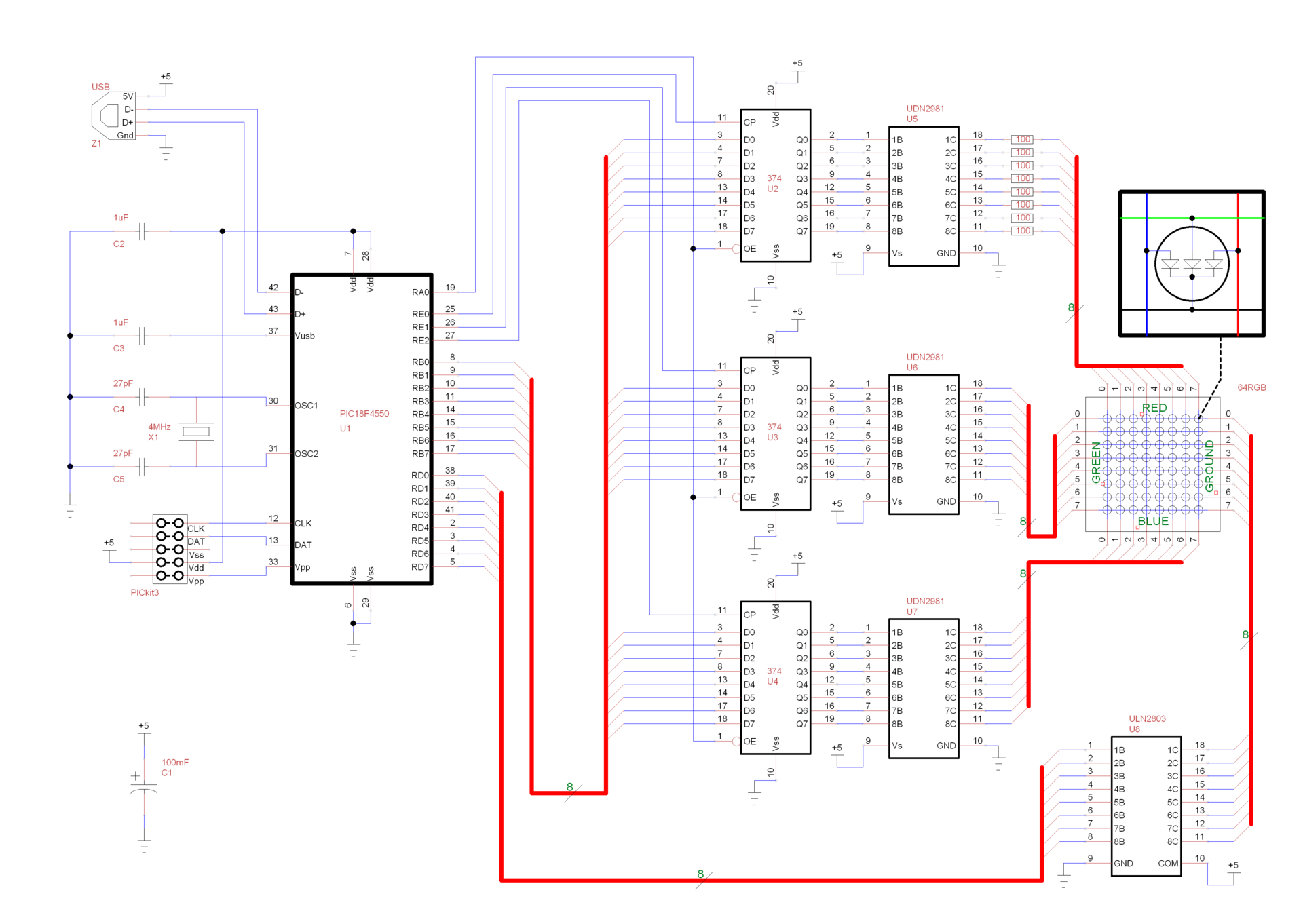
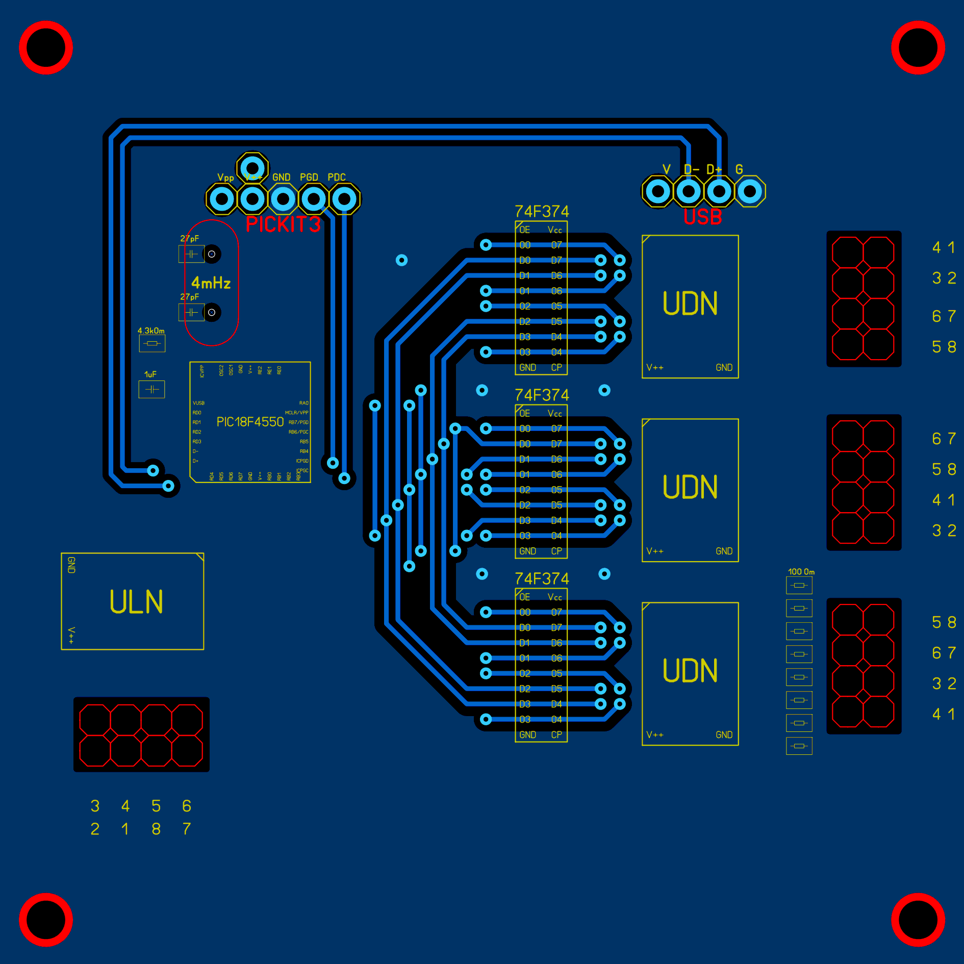
Pay
Lay6 drawings - download
Graphics
основной модуль сторона 1
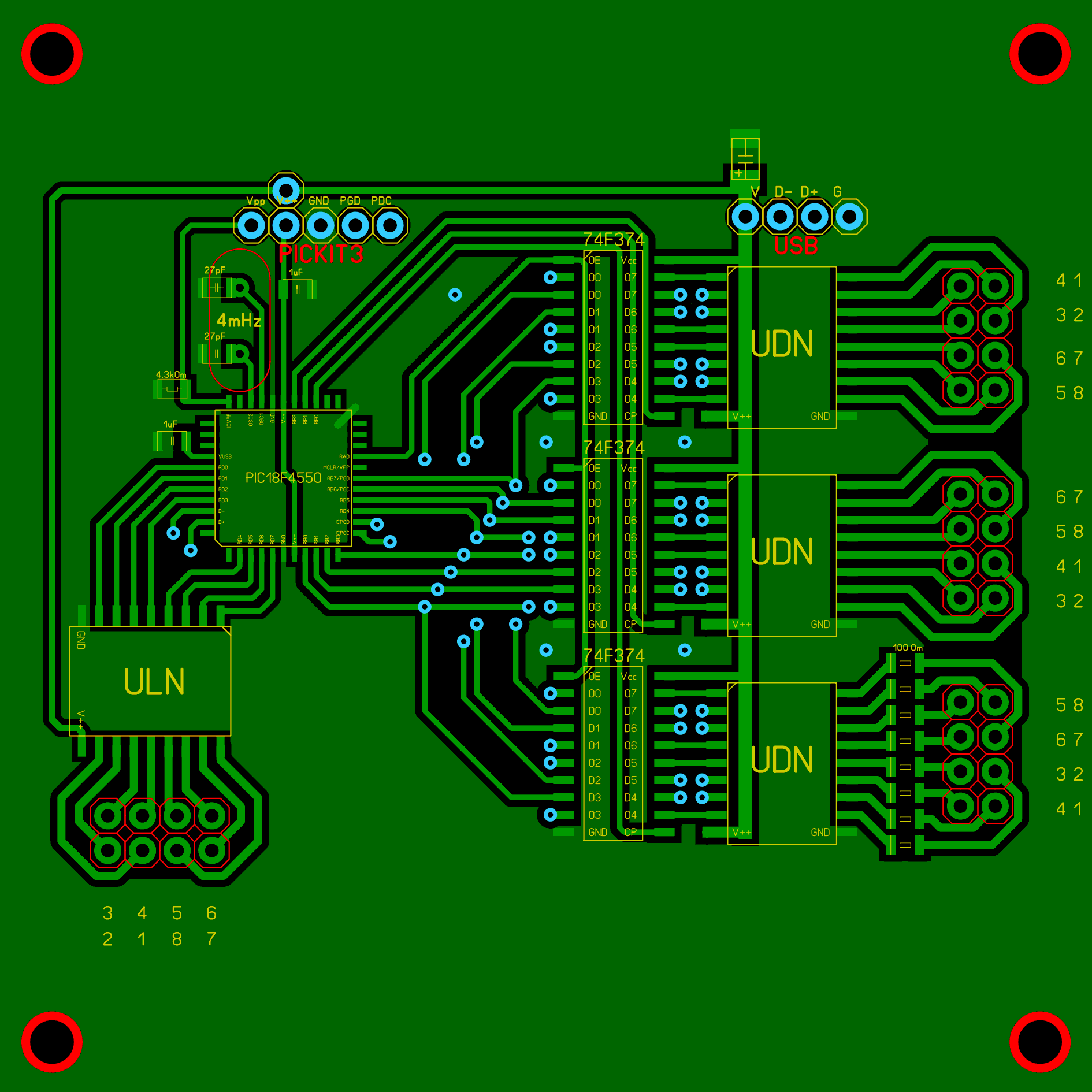
основной модуль сторона 2
модуль светодиодов (обратите внимание, что синим отмечена проволочная перемычка, соединяющая столбцы)
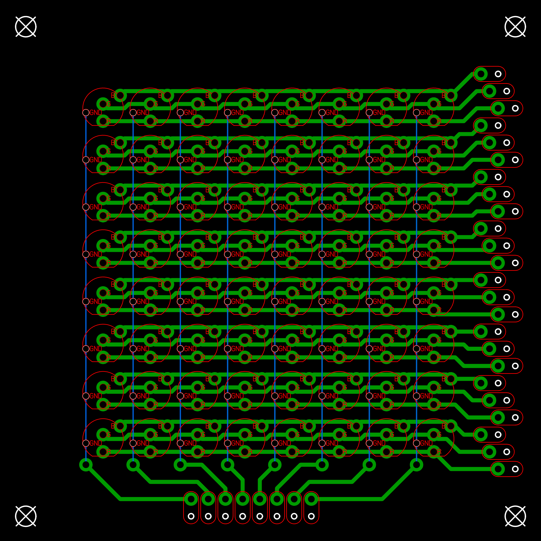
матрица крепления светодиодов
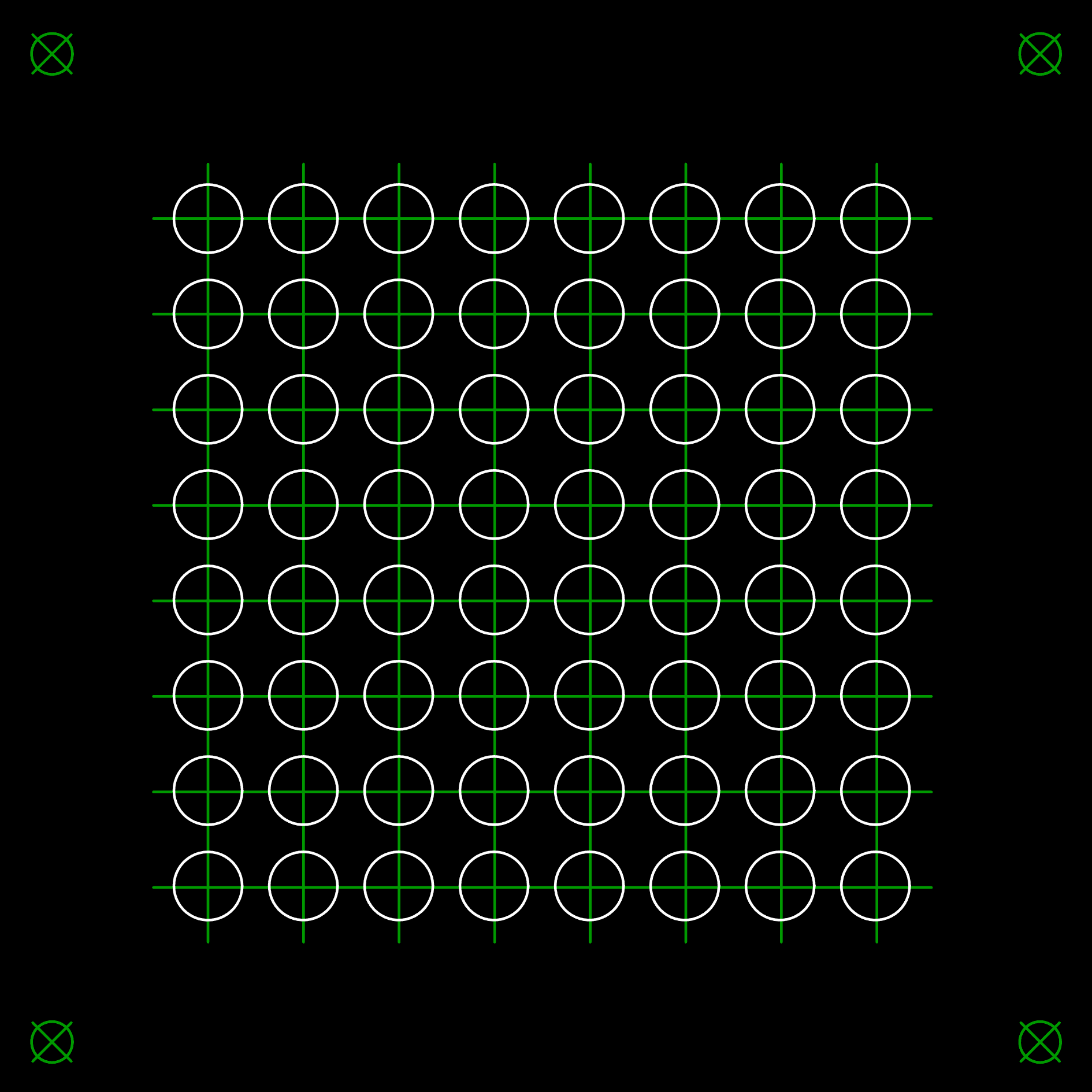
основной модуль сторона 2
модуль светодиодов (обратите внимание, что синим отмечена проволочная перемычка, соединяющая столбцы)
матрица крепления светодиодов
Firmware
Sources and compiled HEX to MPLABX X IDE v2.30 - download
Main code
#ifndef MAIN_C#define MAIN_C// Local includes#include "config.h"#include "usb.h"#include "HardwareProfile.h"#include "usb_function_hid.h"#include "genericHID.h"#define UdnOn           LATA&=0b11111110#define UdnOff          LATA|=0b00000001#define UlnOn           LATD#define UlnOff          LATD =0b00000000#define LineBufer       LATB#define WriteR          LATE|=0b00000001#define WriteG          LATE|=0b00000010#define WriteB          LATE|=0b00000100#define WriteRst        LATE =0b00000000#define Columns         8#define BrightLevels    6#define BlockSize       (Columns*BrightLevels)#define MinBright       0b11111111
unsigned char cursor;
unsigned char bright;
unsigned char column;
unsigned char dataR[BlockSize];
unsigned char dataG[BlockSize];
unsigned char dataB[BlockSize];
voidProcessIO(void) {
    unsigned char temp = BlockSize + 1;
    // If we are not in the configured state just returnif ((USBDeviceState < CONFIGURED_STATE) || (USBSuspendControl == 1)) return;
    //Check if data was received from the host.if (!HIDRxHandleBusy(USBOutHandle))
    {
        switch (ReceivedDataBuffer[0])
        {
            case0x80: // get red packetwhile (--temp) dataR[temp-1] = ReceivedDataBuffer[temp];
                break;
            case0x81: // get green packetwhile (--temp) dataG[temp-1] = ReceivedDataBuffer[temp];
                break;
            case0x82: // get blue packetwhile (--temp) dataB[temp-1] = ReceivedDataBuffer[temp];
                break;
            case0x90: // start
                column = 0b00000001;
                cursor = BlockSize;
                bright = MinBright;
                TMR0ON = 1;
                SWDTEN = 0;
                break;
            case0x91: // stop
                UdnOff;
                UlnOff;
                TMR0ON = 0;
                SWDTEN = 0;
                break;
            case0x92: // power off
                UdnOff;
                UlnOff;
                TMR0ON = 0;
                SWDTEN = 0;
                SLEEP();
                break;
        }
        // Re-arm the OUT endpoint for the next packet
        USBOutHandle = HIDRxPacket(HID_EP, (BYTE*) & ReceivedDataBuffer, 64);
    }
}
voidmain(void)
{
    // Set all port as digital input/output
    PCFG3   = 1;
    // Clear all ports//          76543210
    PORTA   = 0b00000000;
    PORTB   = 0b00000000;
    PORTC   = 0b00000000;
    PORTD   = 0b00000000;
    PORTE   = 0b00000000;
    // Configure ports (1 - inputs; 0 - outputs)//          76543210
    TRISA   = 0b00000000;
    TRISB   = 0b00000000;
    TRISC   = 0b00000000;
    TRISD   = 0b00000000;
    TRISE   = 0b00000000;
    // Configure interrupts for Timer0//          76543210
    INTCON  = 0b10100000;
    // Configure Timer0 as 8bit and 128 prescaler//          76543210
    T0CON   = 0b01000110;
    USBDeviceInit();
    while(1)
    {
        // Check bus status and service USB interrupts.
        USBDeviceTasks();
        // Application-specific tasks.
        ProcessIO();
    };
}
void interrupt tc_int() // High priority interrupt
{
    UdnOff;
    UlnOff;
    LineBufer = dataR[cursor-1]; WriteR;
    LineBufer = dataG[cursor-1]; WriteG;
    LineBufer = dataB[cursor-1]; WriteB;
    UdnOn;
    UlnOn = column;
    WriteRst;
    TMR0L = bright;
    if (!--cursor) cursor = BlockSize;
    bright <<= 1;
    asm("BTFSS _bright, 5, 0"); asm("RLNCF _column, 1, 0");
    asm("BTFSS _bright, 5, 0"); bright = MinBright;
    TMR0IF = 0;
}
#endif
Device in operation
To control, I use an Internet radio player written in C, based on the BASS.DLL library. A demo with a gradient across the entire available color palette works during pause, the frame refresh rate (packets sent to the device) - 20 Hz. When playing music, the visualizer that uses the FFT array, obtained by BASS.DLL, works. The frame refresh rate (packets transmitted to the device) in this mode is 29 Hz.
Gradient
Visualizer
музыка: Tape Five — Soulsalicious
музыка: Tape Five — Soulsalicious
Note: The video was shot through the glass from sunglasses (so you can not see the black dots of the vertical scan) and without frosted glass (it interferes with focusing). Since my LEDs are not matte, I stoch the lens on them and treated it with an engraver.
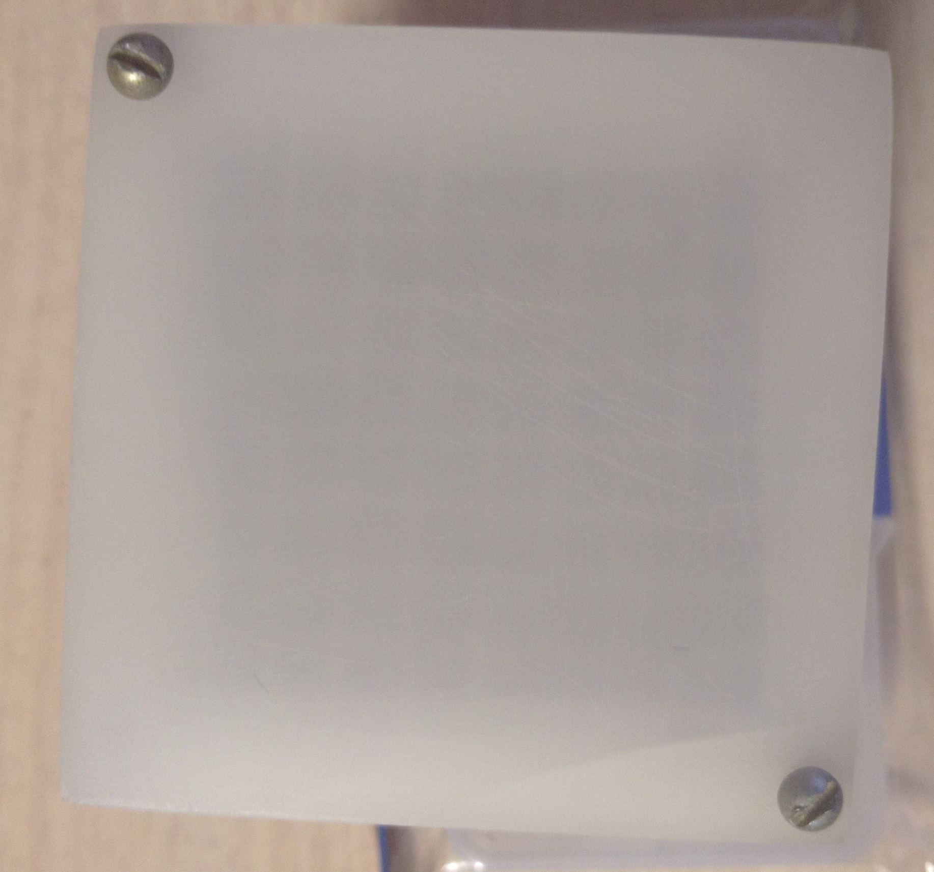
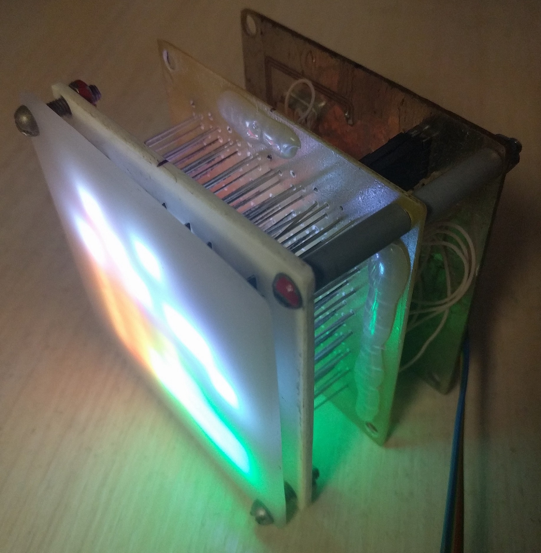
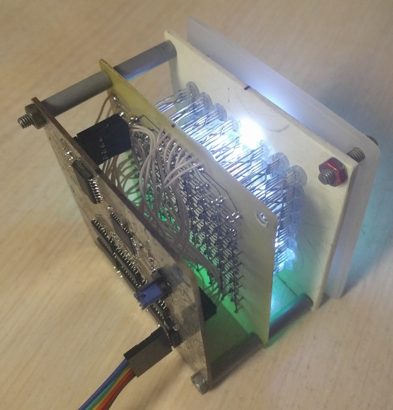
Photo assembled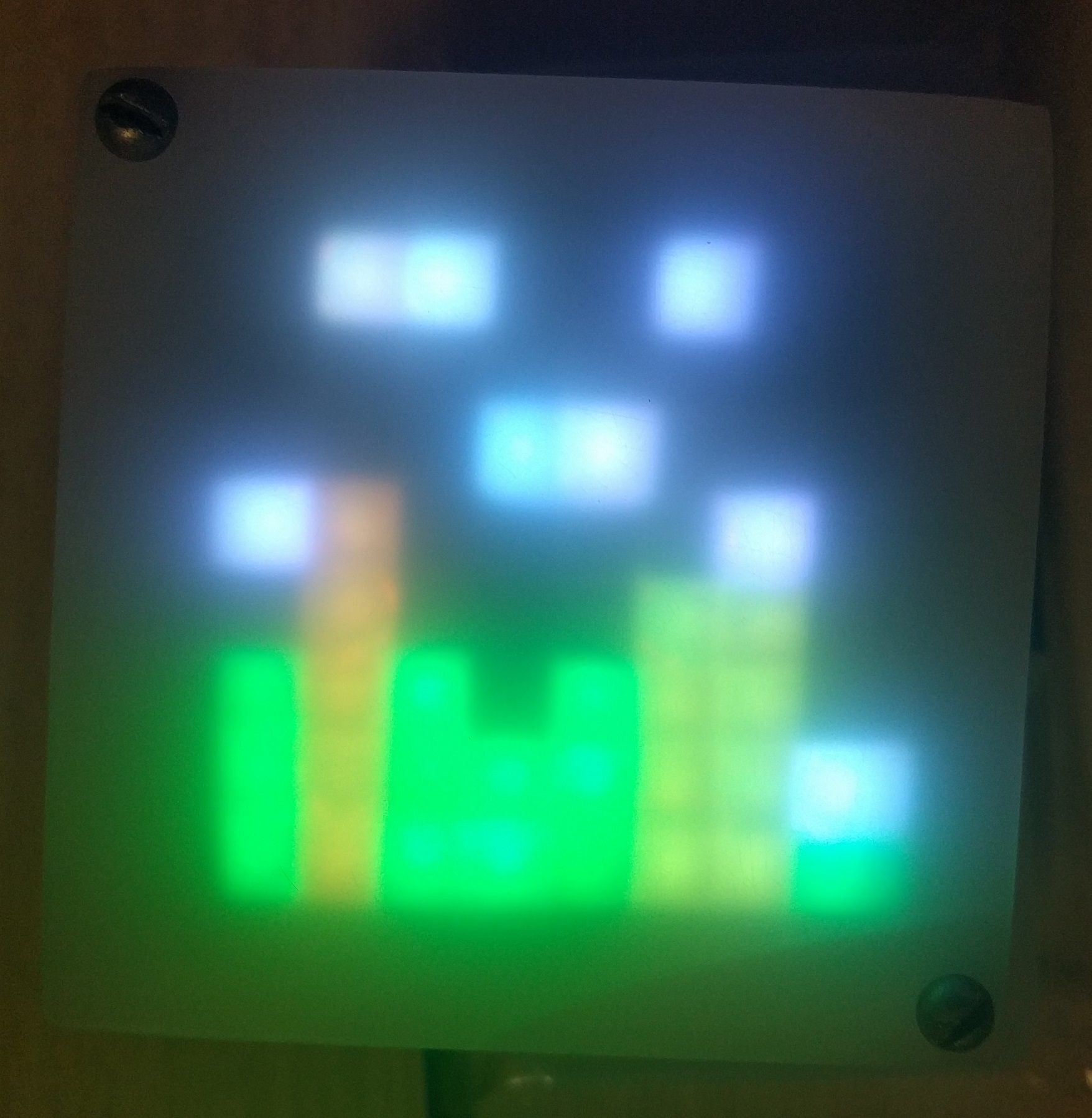
What can be improved
- replace keys with faster ones (especially for UDN)
- implement USB operation through interrupts
- use frosted LEDs or smd to simplify light scattering and mixing
- 74F374 is better to use 74HC574 in place, which will greatly simplify the layout of the board
- add capacitance to each 74F374 circuit to protect against interference
- 74HC138 descrambler can be used to select columns, which will save the legs of the MK
- To reduce the cost of the circuit, you can use LEDs with a common anode and use 3 cheaper ULN keys instead of UDN