Industry Foundation Classes. Brief introduction
Introduction
In connection with the policy of the Party and the Government , there is an active change in legislation in order to introduce BIM technology - Building Information Modeling. In continuation of the Party line, we will consider the open presentation format BIM - IFC (Industry Foundation Classes).
The history of IFC begins in 1995 (in fact, in the summer of 1993 [1] ), when Autodesk Corporation with a group of "comrades" organized a cartel agreement to develop an exchange format for various CAD systems for building design. A year later, the comrades came to the understanding that this format should be open and developed by an organization with open membership, as the International Alliance for Interoperability appeared in 1996. Later, in 2008, the organization was renamed buildingSMART - for greater glamor.
IFC developers did not have a rich imagination, and did not have the opportunity to apply it - they were set very modest deadlines, and the task looked very global. Therefore, they took the STEP format (Standard for the Exchange of Product model data), or rather Application Protocol 225: Building Elements as the basis. I must say that around STEP a rich infrastructure has been created in the form of a bunch of specifications in the status of ISO standards. This infrastructure is based on the EXPRESS data modeling language and its graphical incarnation EXPRESS-G; this language was developed for the convenience of automatically generating code in various programming languages.
The development of IFC began in September 1995, IFC 1.0 was published in June 1996, final version was in January 1997. In fact, the goal of the first version of IFC was to demonstrate the very possibility of realizing the goal, various companies presented their export / import demonstrations in this format.
The next version was released in November 1997 - 1.5, but an attempt to implement it quickly revealed many errors that required the development of a fixed version 1.5.1, which was introduced in parallel with the development of version 2.0 - which was introduced in March 1999.
All these versions are now deprecated.
Version 2.1 was released in November 2000. This is the oldest version for which documentation is available. It was later published as ISO / PAS 16739: 2005.
Now the most common version (which most programs understand) is IFC 2.3.
| Release date | date | Identifier | Documentation | ISO-Standard |
|---|---|---|---|---|
| 4.2.0.0 | 2019 | IFC4X2 | IFC 4.2 | |
| 4.1.0.4 | 2018 | IFC4X1 | IFC 4.1 | |
| 4.0.2.1 | 2017 | IFC4 | IFC 4.0 Addendum 2 TC1 | ISO 16739-1: 2017 |
| 4.0.2.0 | 2016 | IFC4 | IFC 4.0 Addendum 2 | |
| 4.0.1.0 | 2015 | IFC4 | IFC 4.0 Addendum 1 | |
| 4.0.0.5 | 2013 | IFC4 | IFC 4.0 | ISO 16739: 2013 |
| 2.3.0.1 | 2007 | IFC2X3_FINAL | IFC 2x3 TC1 | |
| 2.3.0.0 | 2006 | IFC2X3_FINAL | IFC 2x3 | |
| 2.2.1.0 | 2004 | IFC2X2_FINAL | IFC 2x2 Addendum 1 | |
| 2.2.0.0 | 2003 | IFC2X2_FINAL | IFC 2x2 | |
| 2.1.1.0 | 2001 | IFC2X_FINAL | IFC 2x Addendum 1 | |
| 2.1.0.0 | 2000 | IFC2X_FINAL | IFC 2x | ISO / PAS 16739: 2005 |
| 2.0.0.0 | 1999 | IFC 2.0 | ||
| 1.5.1.0 | 1998 | IFC 1.5.1 | ||
| 1.5.0.0 | 1997 | IFC 1.5 | ||
| 1.0.0.0 | 1996 | IFC 1.0 |
Software
For reading IFC, a text editor with syntax highlighting is useful, for example, I used n ++ and vs code with my clumsy IFC syntax settings.
But another necessary tool will be a program capable of visualizing graphics in IFC. Now there are many viewers for this and even free ones; personally, I prefer XbimXplorer from the xBIM project . I also used Revit, but I must say that pure Revit is not very friendly with IFC - it is not even able to read the file that it created (yes, Autodesk’s Revit is not able to work with the format invented by Autodesk - this is Autodesk’s calling card 'but they just didn’t come up with Revit, but bought it - as usual), but he doesn’t have a bad plugin for this - IFC for Revit(while writing an article - he found several errors, it will be necessary to fix it when there is time ...)
It must be said that the IFC format is so confusing that no program handles it correctly - each does it in its own way. So XbimXplorer ignores 2d graphics and some syntax errors.
Description
IFC format exists in three forms: IFC-SPF (.ifc), IFC-XML (.ifcXML), IFC-ZIP (.ifcZIP)
IFC-SPF is a text format defined in ISO 10303-21 - in fact it is a STEP file
IFC-XML is an XML format defined in ISO 10303-28 (“STEP-XML”)
IFC-ZIP is a zip archive that can contain .ifc or .ifcXML
The structure of the IFC-SPF file is described in ISO 10303-21 (GOST exists ISO 10303-21-2002) in Wirth notation. This is a text file that uses only characters with codes in the range 32-126 (the third edition allows the use of characters with codes 127-255, but is not recommended for compatibility)
Multi-line comments are marked with pairs of characters / * * /
Для записи символов в другой кодировке предусмотрено несколько способов
Запись ISO 8859:
Директива \S\ — код символа после директивы указывает код символа в таблице ISO 8859-1
Директива \P*\ — здесь вместо * должна стоять заглавная латинская буква, она указывает номер таблицы ISO 8859 которая используется для директивы \S\, A означает ISO 8859-1, B означает ISO 8859-2 и т. д.
Запись ISO 10646:
Директива \X\ — за директивой следует двузначное шестнадцатеричное число указывающее символ в диапазоне от U+0000 до U+00FF
Директивы \X2\*\X0\ и \X4\*\X0\ — здесь вместо * идёт последовательность двузначных (X2) или четырёхзначных (X4) шестнадцатеричных чисел, которые обозначают соответствующие символы
Hello World! => \ X2 \ 041F04400438043204350442 \ X0 \, \ X2 \ 041C04380440 \ X0 \!
The maximum length of the raw line is 32769 bytes.
File structure - the file begins with the line ISO-10303-21; and ends with the line END-ISO-10303-21; though there may still be a SIGNATURE_SECTION signature section, but I will not consider this option.
Between these lines there should be a HEADER_SECTION header section, after it there can be ANCHOR_SECTION and / or REFERENCE_SECTION sections, as well as one or more DATA_SECTION (in IFC there is only one)
HEADER_SECTION - IFC header section structure allows only three elements in this section: FILE_DESCRIPTION, FILE_NAME, FILE_SCHEMA Minimum option: FILE_DESCRIPTION (('ViewDefinition [CoordinationView_V2.0]'), '2; 1');
ENTITY file_description;

 description : LIST [1:?] OF STRING (256) ;

 implementation_level : STRING (256) ;

END_ENTITY;
The content of the description is very important for IFC - it lists the used ViewDefinition add-ons, the ExchangeRequirement content and Option [2] , but only the ViewDefinition
implementation_level element is mandatory, it consists of two digits, the first indicates the ISO-10303-21 edition, the second indicates the mode compatibility (there are two of them) are described in clause 4.3 of ISO-10303-21. For IFC, implementation_level always has a value of-2; 1
Another option:
FILE_DESCRIPTION (('ViewDefinition [CoordinationView_V2.0, QuantityTakeOffAddOnView]', 'ExchangeRequirement [Structural]'), '2; 1'); All values can be left blank. File name, time stamp, author, organization, preprocessor version, authoring program, authorization.
ENTITY file_name;

 name : STRING (256) ;

 time_stamp : time_stamp_text ;

 author : LIST [ 1 : ? ] OF STRING (256) ;

 organization : LIST [ 1 : ? ] OF STRING (256) ;

 preprocessor_version : STRING (256) ;

 originating_system : STRING (256) ;

 authorization : STRING (256) ;

END_ENTITY;
ENTITY file_schema;
schema_identifiers : LIST [1:?] OF UNIQUE schema_name;
END_ENTITY;The name of the schema that describes the contents of the data section (see the Identifier column in the table above)
The data section begins with the DATA keyword; and ends with ENDSEC ;. The contents of this section is a sequence of entities with the following syntax:
# <entity index> = <entity name> (<list of attributes>);
Possible entities and their parameters are described in the IFC chart.
Empty IFC file:
ISO-10303-21;

HEADER;

FILE_DESCRIPTION(('ViewDefinition [CoordinationView_V2.0]'),'2;1');

FILE_NAME('','',(''),(''),'','','');

FILE_SCHEMA(('IFC2X3'));

ENDSEC;

DATA;

ENDSEC;

END-ISO-10303-21;
Data section
The root element of IFC is IfcProject . Here it is necessary to tell how the list of attributes is formed, which is necessary for creating the entity, firstly, the entity can have its own attributes, and secondly, it can inherit them from the ancestor, the order of the attributes is specified - from the ancestor to the descendant. For IfcProject, the inheritance chain will be as follows: IfcRoot => IfcObjectDefinition => IfcObject => IfcProject. Now, to create an IfcProject, we need to set the values for all attributes. The first attribute inherited from IfcRoot - GlobalId, has the value IfcGloballyUniqueId. This is a simple type - a string with a length of 22 characters, you need to write a unique GUID or UUID in them, so that a 128-bit number is shoved into 22 characters - there is a special algorithm published on the buildingSMART website [3]
IFCPROJECT(,,<Имя>,<Описание>,, ,, (),); . The following OwnerHistory attribute is set to IfcOwnerHistory. This element answers the questions - who, how and when created this IFC element, in fact, for almost every object in IFC its author can be indicated through this element. To fill this attribute, you can create an element "in place", but it is better to do it in another place, and in place just refer to it with a record of the form # <entity index>. Also, the $ symbol means a null value, the * symbol is used if the descendant assigns the value to the attribute of the ancestor. Values of type enum are written between two points - .ELEMENT.
IfcProject example: The following elements <Name>, <Description>,
#1=IFCPROJECT('abcdefghijklmnopqrs101', #2, 'sample project', $, $, '','',$,$);

#2=IFCOWNERHISTORY(#3,#6,.READWRITE.,.ADDED.,87763554,#3,#6,87763554);

#3=IFCPERSONANDORGANIZATION(#4,#5,());

#4=IFCPERSON('Public','Jane','Q.',(),(),(),(),());

#5=IFCORGANIZATION($,'Architecture by Jane Q. Public, Inc.',$,(),());

#6=IFCAPPLICATION(#7,'Version 1.0','Building Architecture Toolkit','BAT1.0');

#7=IFCORGANIZATION($,'Creating Instance Software, Inc.',$,(),());RepresentationContexts- this is a list of spaces / contexts, the idea was that we can have several spaces / contexts, for example: sketch, project and working documentation. And different objects may have different representations in different contexts. For example, the wall in the sketch is just a line, in the project it already has a thickness, and in the working documentation it consists of different layers. But in IFC2x3 the concept has changed, the contexts of 'Sketch', 'Outline', 'Design', 'Detail' have either been canceled or they moved to IfcGeometricRepresentationSubContext. And the class IfcRepresentationContext itself became abstract, with a single descendant - IfcGeometricRepresentationContext, which can be volumetric ContextType = 'Model', CoordinateSpaceDimension = 3, flat ContextType = 'Plan', CoordinateSpaceDimension = 2 and FIG knows what ContextType = '
IFCGEOMETRICREPRESENTATIONCONTEXT(<Имя>,<Тип>,<Размерность пространства>,<Точность - расстояние на котором точки считаются идентичными>,<Система координат>,<Направление на север>)UnitsInContext - an IfcUnitAssignment object that forms a list of IfcUnit elements with a description of the units of the project, it is necessary for proper import, otherwise the software will use its default settings - for example, in Revit there are feet (it stores everything in feet). From the root IfcProject element, a tree of elements is formed, the descendants of the IfcSpatialStructureElement type (IfcBuilding (building), IfcBuildingStorey (floor), IfcSpace (space or room), IfcSite (site)). But these elements are not connected directly, but through a special IfcRelAggregates element, in a one-to-many relationship.
#2= IFCSIUNIT(*,.LENGTHUNIT.,.MILLI.,.METRE.);

#3= IFCSIUNIT(*,.AREAUNIT.,$,.SQUARE_METRE.);

#4= IFCSIUNIT(*,.VOLUMEUNIT.,$,.CUBIC_METRE.);

#5= IFCSIUNIT(*,.PLANEANGLEUNIT.,$,.RADIAN.);

#6= IFCUNITASSIGNMENT((#2,#3,#4,#5));
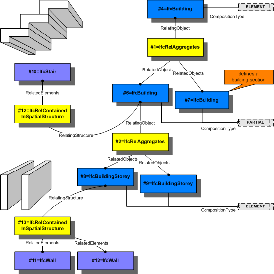
IFCRELAGGREGATES(, , <Имя>, <Описание>, <Родительский элемент>, (<список потомков>)); These elements can only be connected in the following order: IfcSite => IfcBuilding => IfcBuildingStorey => IfcSpace, and elements of the same type can be connected, but then their CompositionType attribute must have a different value and only in a certain order COMPLEX => ELEMENT => PARTIAL
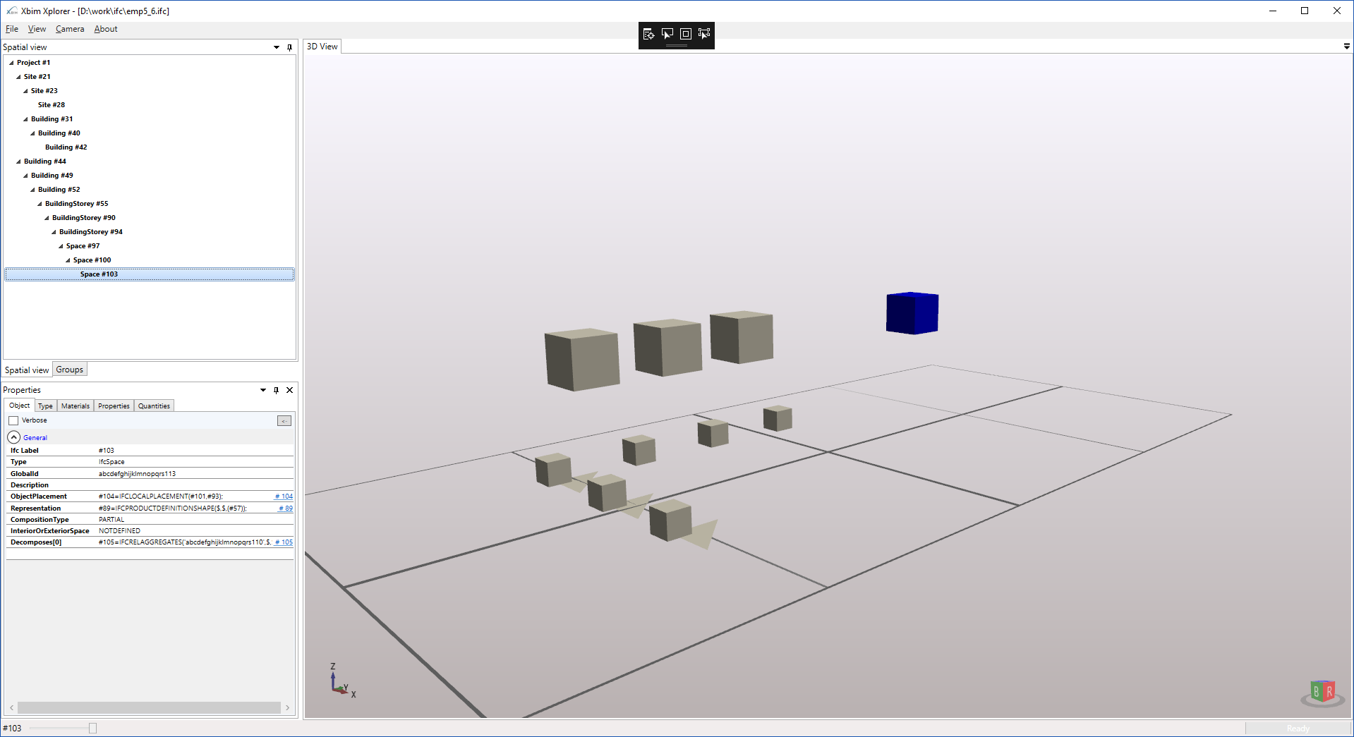
The full possible structure of the project:
IfcSite.COMPLEX => IfcSite.ELEMENT => IfcSite.PARTIAL => IfcBuilding.COMPLEX => IfcBuilding.ELEMENT => IfcBuilding.PARTIAL => IfcBuildingStorey.COMPLEX => IfcBuilding => IfcBuding IfcSpace.COMPLEX => IfcSpace.ELEMENT => IfcSpace.PARTIAL
ifc file
Although all elements are optional, only the inheritance order is required
It is assumed that you are describing a Building, which consists of Storey floors and in which spaces exist, you need to show the existing Site relief in which you enter your building. The Representation attribute inherited from IfcProduct points to an object IfcProductRepresentation, has two descendants of IfcProductDefinitionShape - to describe the shape of the object and IfcMaterialDefinitionRepresentation - the description of the material (visualization style), they connect various representations through the Representations attribute. IfcMaterialDefinitionRepresentation for Representations accepts only IfcStyledRepresentation - style descriptions The RepresentedMaterial attribute gives a textual description of the material of the object.
IFCSITE(,,<Имя>,<Описание>,,,,,,,,,,); IfcProductDefinitionShape(<Имя>,<Описание>,()) IfcMaterialDefinitionRepresentation(<Имя>, <Описание>,),) IfcProductDefinitionShape for Representations accepts only IfcShapeRepresentation or IfcTopologyRepresentation (IfcShapeModel)
IfcShapeRepresentation is the most important class in IFC because it is responsible for the geometric representation of objects. Available geometry types: Curve2D (flat lines), GeometricSet (points, lines, surfaces, 2d and 3d), SurfaceModel (surfaces), SolidModel (bodies), additional types (BoundingBox, SectionedSpine, MappedRepresentation) The basis of any geometry is the IfcCartesianPoint element - just a point. The geometry may simply consist of a list of points, or it may have a complex structure with a bunch of parameters and children. Consider
IFCSHAPEREPRESENTATION(<контекст>,,<тип геометрии>,<список элементов>); #13= IFCCARTESIANPOINT((0.,0.,0.));
#16= IFCCARTESIANPOINT((1.,0.,0.));
#22= IFCPOLYLINE((#13, #16));
#510= IFCBSPLINECURVEWITHKNOTS(3,(#511,#512,#513,#514,#511,#512,#513),.UNSPECIFIED.,.T.,.T.,(1,1,1,1,1,1,1,1,1,1,1),(-7.0,-6.0,-5.0,-4.0,-3.0,-2.0,-1.0,0.0,1.0,2.0,3.0),.UNSPECIFIED.);

#511= IFCCARTESIANPOINT((239.758213537139,192.193559404919,-83.9999999999991));

#512= IFCCARTESIANPOINT((0.0,275.591853484122,-83.9999999999991));

#513= IFCCARTESIANPOINT((-239.75821353295,192.193559404918,-83.9999999999991));

#514= IFCCARTESIANPOINT((0.0,-108.13323051355,-83.9999999999991));
#34= IFCSHAPEREPRESENTATION(#7,'Body','SweptSolid',(#35));

#35= IFCEXTRUDEDAREASOLID(#36,#8,#37,0.5);

#36= IFCRECTANGLEPROFILEDEF(.AREA.,$,#38,0.5,0.5);

#37= IFCDIRECTION((0.,0.,1.));

#38= IFCAXIS2PLACEMENT2D(#39,#9);

#7= IFCGEOMETRICREPRESENTATIONCONTEXT($,'Model',3,0.01,#8,#9);

#8= IFCAXIS2PLACEMENT3D(#10,$,$);

#9= IFCDIRECTION((0.,1.));

#39= IFCCARTESIANPOINT((0.,0.));
IfcExtrudedAreaSolid(,,,) 
This is the body obtained by extruding the original SweptArea planar contour located in the Position space extruded in the direction of ExtrudedDirection to the depth of ExtrudedDirection. The SweptArea attribute is of type IfcProfileDef - this is an abstract class with a large number of descendants "for all occasions", in this case ProfileType is used - the profile type is the enum value of the type IfcProfileTypeEnum (Values: CURVE, AREA). The optional ProfileName profile name, Position positioning, and size by XY coordinates are XDim, YDim.
IfcRectangleProfileDef(,,,,) 
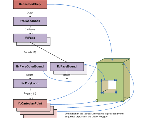
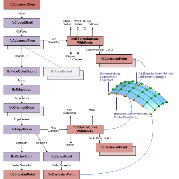
Or the more complex IfcFacetedBrep, it consists of one closed IfcClosedShell, which in turn consists of a list of IfcFace faces, which consist of IfcFaceBound edges, which are described by IfcLoop loops, which already consist of IfcCartesianPoint points. Boundary representation (brep) dictates a lot of conditions on its structure - described in detail in the documentation and related literature. IfcAdvancedBrep has appeared in IFC4, the edges of which can be described by NURBS curves
#57= IFCSHAPEREPRESENTATION(#7, 'Body', 'Brep', (#58));

#58= IFCFACETEDBREP(#59);

#59= IFCCLOSEDSHELL((#80, #81, #82, #83, #84, #85));


#60 = IFCCARTESIANPOINT((0.,0.,0.));

#61 = IFCCARTESIANPOINT((1.,0.,0.));

#62 = IFCCARTESIANPOINT((1.,1.,0.));

#63 = IFCCARTESIANPOINT((0.,1.,0.));

#64 = IFCCARTESIANPOINT((0.,0.,1.));

#65 = IFCCARTESIANPOINT((1.,0.,1.));

#66 = IFCCARTESIANPOINT((1.,1.,1.));

#67 = IFCCARTESIANPOINT((0.,1.,1.));


#68= IFCPOLYLOOP((#60, #61, #62, #63));

#69= IFCPOLYLOOP((#64, #65, #66, #67));

#70= IFCPOLYLOOP((#60, #61, #65, #64));

#71= IFCPOLYLOOP((#61, #62, #66, #65));

#72= IFCPOLYLOOP((#62, #63, #67, #66));

#73= IFCPOLYLOOP((#63, #60, #64, #67));


#74= IFCFACEOUTERBOUND(#68, .T.);

#75= IFCFACEOUTERBOUND(#69, .T.);

#76= IFCFACEOUTERBOUND(#70, .T.);

#77= IFCFACEOUTERBOUND(#71, .T.);

#78= IFCFACEOUTERBOUND(#72, .T.);

#79= IFCFACEOUTERBOUND(#73, .T.);


#80= IFCFACE((#74));

#81= IFCFACE((#75));

#82= IFCFACE((#76));

#83= IFCFACE((#77));

#84= IFCFACE((#78));

#85= IFCFACE((#79));
IfcSpatialStructureElement objects can have their own geometry, but in general, buildings consist of other objects: walls, floors, roofs, windows, doors, etc. In IFC, all these objects are described by the corresponding objects: IfcWall, IfcSlab, IfcRoof, IfcWindow, IfcDoor - all they are descendants of IfcProduct. All these objects can be associated with the corresponding IfcSpatialStructureElement object, through a special IfcRelContainedInSpatialStructure object. For walls of constant thickness, it is customary to use IfcWallStandardCase (considered obsolete in IFC4), for other cases we use IfcWall. In case of IfcWallStandardCase you need to use SweptSolid - extruding wall contour to a given height
IFCRELCONTAINEDINSPATIALSTRUCTURE(,,<Имя>,<Описание>, (),) IFCWALLSTANDARDCASE(,,<Имя>,<Описание>,,,,); #8= IFCAXIS2PLACEMENT3D(#10,$,$);
#10= IFCCARTESIANPOINT((0.,0.,0.));
#13= IFCLOCALPLACEMENT($,#8);
#22= IFCDIRECTION((0.,0.,1.));
#23= IFCAXIS2PLACEMENT2D(#24,#25);
#24= IFCCARTESIANPOINT((0.,0.));
#25= IFCDIRECTION((1.,0.));
#26= IFCWALLSTANDARDCASE('abcdefghijklmnopqrs107',$,'wall1',$,'',#13,#27,'');
#27= IFCPRODUCTDEFINITIONSHAPE($,$,(#28));
#28= IFCSHAPEREPRESENTATION(#7,'Body','SweptSolid',(#29));
#29= IFCEXTRUDEDAREASOLID(#30,#32,#22,1000.);
#30= IFCRECTANGLEPROFILEDEF(.AREA.,$,#23,100.,1000.);
#31= IFCCARTESIANPOINT((500.,0.,100.));
#32= IFCAXIS2PLACEMENT3D(#31,$,$);
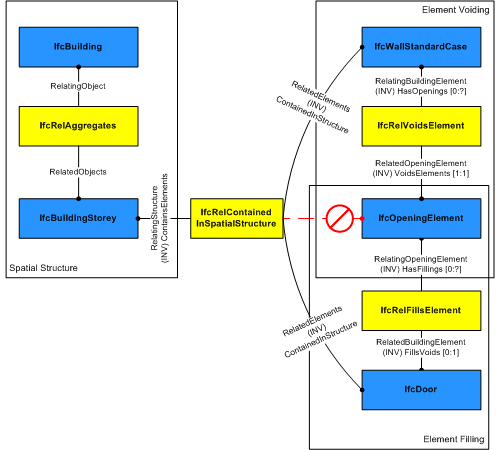
The door is described by an IfcDoor object, it can be added to IfcRelContainedInSpatialStructure, but this object does not make a “cut” in the wall for itself.
A “IfcOpeningElement” is responsible for the “cut”, which is associated with the “parent” object through IfcRelVoidsElement. In IfcOpeningElement, you can “insert” a door using the IfcRelFillsElement object. With IfcOpeningElement you can make not only through holes, but also recesses. IfcWindow object is very similar in use, ifcDoor, OverallHeight, OverallWidth - nominal dimensions, you can not specify - then these values will be taken from the geometry
IFCDOOR(,,<Имя>,<Описание>,,,,,,) IFCWINDOW(,,<Имя>,<Описание>,,,,,,) IfcRoof object is implied by a complex object - it must describe the entire roof, to connect all children with it - you need to use IfcRelAggregates. But at the same time, IfcRoof can have its own Representation geometry.
IFCSLAB(,,<Имя>,<Описание>,,,,,); IFCROOF(,,<Имя>,<Описание>,,,,,); Writing IFC
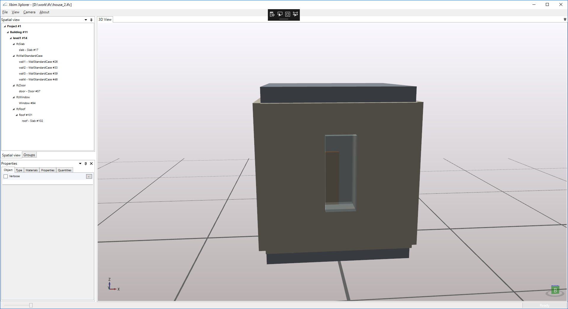
Now, armed with this knowledge, we will try to describe a simple house, for a start we will take an empty IFC file - the description of which I have already given
empty IFC file
ISO-10303-21;

HEADER;

FILE_DESCRIPTION(('ViewDefinition [CoordinationView_V2.0]'),'2;1');

FILE_NAME('','',(''),(''),'','','');

FILE_SCHEMA(('IFC2X3'));

ENDSEC;

DATA;

ENDSEC;

END-ISO-10303-21;
Next, we need to fill the contents of the DATA section. The first required object must be IFCPROJECT (although it can be at the end of the file, but it just needs to be), we also need IFCUNITASSIGNMENT, if we certainly want the programs to read the model in the units of measure that we have in mind. We will also need at least one IFCGEOMETRICREPRESENTATIONCONTEXT - otherwise we will not be able to add a description of the geometry.
IFCPROJECT, IFCUNITASSIGNMENT, IFCGEOMETRICREPRESENTATIONCONTEXT
#1=IFCPROJECT('abcdefghijklmnopqrs101', $, 'Project #1', $, $, '','', (#7), #6);


/* Единицы измерений модели */

#2= IFCSIUNIT(*,.LENGTHUNIT.,.MILLI.,.METRE.);

#3= IFCSIUNIT(*,.AREAUNIT.,$,.SQUARE_METRE.);

#4= IFCSIUNIT(*,.VOLUMEUNIT.,$,.CUBIC_METRE.);

#5= IFCSIUNIT(*,.PLANEANGLEUNIT.,$,.RADIAN.);

#6= IFCUNITASSIGNMENT((#2,#3,#4,#5));


/* Контекст */

#7= IFCGEOMETRICREPRESENTATIONCONTEXT($,'Model',3,0.01,#8,#9);

#8= IFCAXIS2PLACEMENT3D(#10,$,$);

#9= IFCDIRECTION((0.,1.));

#10= IFCCARTESIANPOINT((0.,0.,0.));
House structure
IFCBUILDING => IFCBUILDINGSTOREY => IFCRELCONTAINEDINSPATIALSTRUCTURE
/* Дом */

#11= IFCBUILDING('abcdefghijklmnopqrs102', $, $, $, $, #13, $, $, .ELEMENT., $, $, $);

#12= IFCRELAGGREGATES('abcdefghijklmnopqrs103', $, $, $, #1, (#11));

#13= IFCLOCALPLACEMENT($,#8);


/* Этаж */

#14= IFCBUILDINGSTOREY('abcdefghijklmnopqrs104',$,'level1',$,'',#13,$,'',.ELEMENT.,0.);

#15= IFCRELAGGREGATES('abcdefghijklmnopqrs103', $, $, $, #11, (#14));


#16= IFCRELCONTAINEDINSPATIALSTRUCTURE('abcdefghijklmnopqrs105',$,$,$,(#17, #26, #33, #39, #46, #57, #94, #101),#14);
Let's describe the gender - IFCSLAB
#17= IFCSLAB('abcdefghijklmnopqrs106',$,'slab',$,'',#13,#18,'',.BASESLAB.);

#18= IFCPRODUCTDEFINITIONSHAPE($,$,(#19));

#19= IFCSHAPEREPRESENTATION(#7,'Body','SweptSolid',(#20));

#20= IFCEXTRUDEDAREASOLID(#21,#8,#22,100.);

#21= IFCRECTANGLEPROFILEDEF(.AREA.,$,#23,1000.,1000.);

#22= IFCDIRECTION((0.,0.,1.));

#23= IFCAXIS2PLACEMENT2D(#24,#25);

#24= IFCCARTESIANPOINT((0.,0.));

#25= IFCDIRECTION((1.,0.));
Four walls
#26= IFCWALLSTANDARDCASE('abcdefghijklmnopqrs107',$,'wall1',$,'',#13,#27,'');

#27= IFCPRODUCTDEFINITIONSHAPE($,$,(#28));

#28= IFCSHAPEREPRESENTATION(#7,'Body','SweptSolid',(#29));

#29= IFCEXTRUDEDAREASOLID(#30,#32,#22,1000.);

#30= IFCRECTANGLEPROFILEDEF(.AREA.,$,#23,100.,1000.);

#31= IFCCARTESIANPOINT((500.,0.,100.));

#32= IFCAXIS2PLACEMENT3D(#31,$,$);


#33= IFCWALLSTANDARDCASE('abcdefghijklmnopqrs108',$,'wall2',$,'',#13,#34,'');

#34= IFCPRODUCTDEFINITIONSHAPE($,$,(#35));

#35= IFCSHAPEREPRESENTATION(#7,'Body','SweptSolid',(#36));

#36= IFCEXTRUDEDAREASOLID(#30,#38,#22,1000.);

#37= IFCCARTESIANPOINT((-500.,0.,100.));

#38= IFCAXIS2PLACEMENT3D(#37,$,$);


#39= IFCWALLSTANDARDCASE('abcdefghijklmnopqrs110',$,'wall3',$,'',#13,#40,'');

#40= IFCPRODUCTDEFINITIONSHAPE($,$,(#41));

#41= IFCSHAPEREPRESENTATION(#7,'Body','SweptSolid',(#42));

#42= IFCEXTRUDEDAREASOLID(#43,#45,#22,1000.);

#43= IFCRECTANGLEPROFILEDEF(.AREA.,$,#23,1000.,100.);

#44= IFCCARTESIANPOINT((0.,-500.,100.));

#45= IFCAXIS2PLACEMENT3D(#44,$,$);


#46= IFCWALLSTANDARDCASE('abcdefghijklmnopqrs109',$,'wall4',$,'',#13,#47,'');

#47= IFCPRODUCTDEFINITIONSHAPE($,$,(#48));

#48= IFCSHAPEREPRESENTATION(#7,'Body','SweptSolid',(#49));

#49= IFCEXTRUDEDAREASOLID(#50,#52,#22,1000.);

#50= IFCRECTANGLEPROFILEDEF(.AREA.,$,#23,1000.,100.);

#51= IFCCARTESIANPOINT((0.,500.,100.));

#52= IFCAXIS2PLACEMENT3D(#51,$,$);
Door
#57= IFCDOOR('abcdefghijklmnopqrs111',$,'door',$,'',#88,#86,'',$,$);
#86= IFCPRODUCTDEFINITIONSHAPE($,$,(#87));
#87= IFCSHAPEREPRESENTATION(#7,'Body','Brep',(#58));
#58= IFCFACETEDBREP(#59);
#59= IFCCLOSEDSHELL((#80, #81, #82, #83, #84, #85));
#60 = IFCCARTESIANPOINT((0.,0.,0.));
#61 = IFCCARTESIANPOINT((200.,0.,0.));
#62 = IFCCARTESIANPOINT((200.,200.,0.));
#63 = IFCCARTESIANPOINT((0.,200.,0.));
#64 = IFCCARTESIANPOINT((0.,0.,500.));
#65 = IFCCARTESIANPOINT((200.,0.,500.));
#66 = IFCCARTESIANPOINT((200.,200.,500.));
#67 = IFCCARTESIANPOINT((0.,200.,500.));
#68= IFCPOLYLOOP((#60, #61, #62, #63));
#69= IFCPOLYLOOP((#64, #65, #66, #67));
#70= IFCPOLYLOOP((#60, #61, #65, #64));
#71= IFCPOLYLOOP((#61, #62, #66, #65));
#72= IFCPOLYLOOP((#62, #63, #67, #66));
#73= IFCPOLYLOOP((#63, #60, #64, #67));
#74= IFCFACEOUTERBOUND(#68, .T.);
#75= IFCFACEOUTERBOUND(#69, .T.);
#76= IFCFACEOUTERBOUND(#70, .T.);
#77= IFCFACEOUTERBOUND(#71, .T.);
#78= IFCFACEOUTERBOUND(#72, .T.);
#79= IFCFACEOUTERBOUND(#73, .T.);
#80= IFCFACE((#74));
#81= IFCFACE((#75));
#82= IFCFACE((#76));
#83= IFCFACE((#77));
#84= IFCFACE((#78));
#85= IFCFACE((#79));
#88= IFCLOCALPLACEMENT($,#89);
#89= IFCAXIS2PLACEMENT3D(#90,$,$);
#90= IFCCARTESIANPOINT((-100.,400.,100.));
#91= IFCRELVOIDSELEMENT('abcdefghijklmnopqrs112',$,$,$,#46,#92);
#92= IFCOPENINGELEMENT('abcdefghijklmnopqrs113',$,$,$,'Opening',#88,#86,$);
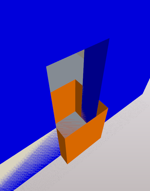
#93= IFCRELFILLSELEMENT('abcdefghijklmnopqrs114',$,$,$,#92,#57);To describe the door, we use IFCFACETEDBREP and use it for the IFCOPENINGELEMENT in which our door is inserted. Using different IFCLOCALPLACEMENTs, we can insert the same geometry in different places and to represent different objects - for example, we can use the same IFCFACETEDBREP for the window.
Window
#94= IFCWINDOW('abcdefghijklmnopqrs115',$,$,$,$,#95,#86,$,$,$);

#95= IFCLOCALPLACEMENT($,#96);

#96= IFCAXIS2PLACEMENT3D(#97,$,$);

#97= IFCCARTESIANPOINT((-100.,-600.,400.));


#98= IFCRELVOIDSELEMENT('abcdefghijklmnopqrs116',$,$,$,#39,#99);

#99= IFCOPENINGELEMENT('abcdefghijklmnopqrs117',$,$,$,'Opening',#95,#86,$);

#100= IFCRELFILLSELEMENT('abcdefghijklmnopqrs118',$,$,$,#99,#94);
Roof
#101= IFCROOF('abcdefghijklmnopqrs119',$,$,$,$,#105,$,$,.FLAT_ROOF.);
#102= IFCSLAB('abcdefghijklmnopqrs120',$,'roof',$,'',#105,#18,'',.ROOF.);
#103= IFCAXIS2PLACEMENT3D(#104,$,$);
#104= IFCCARTESIANPOINT((0.,0.,1100.));
#105= IFCLOCALPLACEMENT(#13,#103);
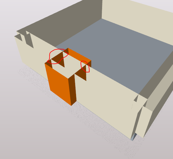
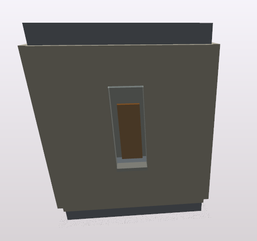
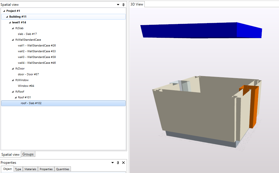
#106= IFCRELAGGREGATES('abcdefghijklmnopqrs121',$,$,$,#101,(#102));finished file
Conclusion
Now, my dear reader, you can write your dream home. Unfortunately, I did not consider IfcMaterialDefinitionRepresentation, which was rejected for the style of displaying objects, did not consider IfcTopologyRepresentation - I do not really understand what it is for and I don’t know how to visualize it. I did not consider the IFC options and additional sets of properties. But otherwise this would not be a brief introduction.
The IFC format contains a huge number of objects, which becomes only more from version to version. In the specification text there are notes that are not reflected in the EXPRESS scheme, but which strongly affect the file processing. Therefore, it is difficult to implement this format without having carefully read all the documentation, but this is hardly possible for one person, therefore there is no program - which reads it absolutely correctly, each has its own peculiarities. And if in the case of open source programs there is always the opportunity to correct the detected errors, for proprietary programs this makes it impossible to fully use the IFC format.
The IFC format is absolutely not suitable for storing information of the general plan section, but currently there is an active work on this section, this work should be completed by the end of April 2020 and be part of IFC5. Also now, work is underway on IFC Road, IFC Airport and IFC4precast (precast). IFC Bridge appeared in IFC4x2, for which they came up with a special geometric object - IfcSectionedSolidHorizontal

Recent changes in IFC bring it very close to GML, even IfcCoordinateReferenceSystem has appeared - a description of the geodetic coordinate system. In this case, IFC focuses on the description of the internal structures of the object, and GML describes its external representation. But the main difference between IFC is that it is possible to refer to the same objects in different places - the same point can be used in the description of the geometry of the wall and window. In GML, each geometric object is completely independent.
References: