RFID front end standard ISO 11785 from an old FM receiver and elevator debris
Introduction
Somehow, in connection with one project, it was proposed to reverse engineer one long-range RFID reader for marked cattle. When studying the finished device, a very original solution was found to build the input part of the reader. A solution of this kind greatly facilitates the work of a radio engineer.
Principle of operation of markers according to ISO 11785 standard in HDX mode
In order to understand how the circuit is built, you need to refresh in memory how the information is transferred according to the ISO 11785 standard in HDX mode.
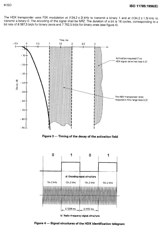
The figure below (squeezing from ISO 11785) shows the coding principle “0” and “1” and the temporal distribution of the pump and reset signals.

It is important that the transfer of data from the tag begins only after the disappearance of the pump signal. The signal from the label itself is frequency-manipulated with a band of 10 kHz, and it can be received, amplified and detected using a standard chip for a household FM receiver with some additions.
Description of the circuit fragment
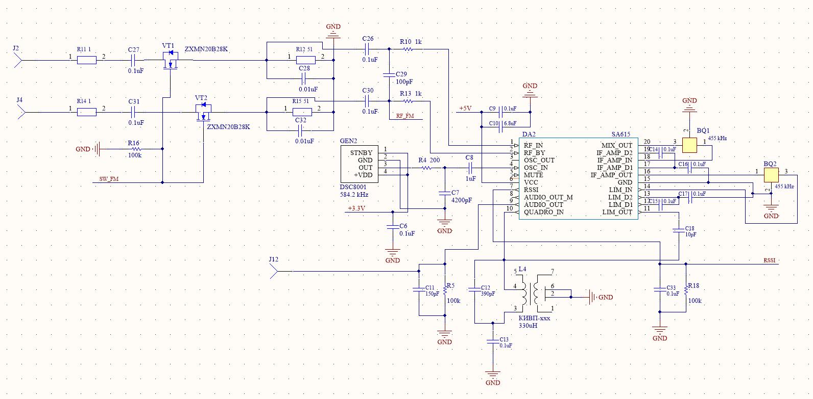
The figure below shows a fragment of the RFID reader circuit, its receiving part for processing HDX signals.
( to view in full size, click on the picture ).

The FM signal receiving and processing unit is based on the well-known SA615 (DA2) microcircuit [1]. For filtering at the intermediate frequency, standard piezoelectric filters of the LTP455A type (BQ1 and BQ2) with a central frequency of 455 and a band of 10 kHz are used. The center frequency of the input signal in the signal manipulation band is 129.2 kHz. Therefore, the upper tuning was applied for the local oscillator, and a MEMS-type generator operating at a frequency of 584.2 kHz (GEN2) was used. T.O. the frequency of the mirror channel is 1039.2 kHz. That when the quality factor of the antenna circuit is at least 20 (and it is higher), the suppression of the mirror channel is at least 18 dB.
The local oscillator signal is fed to the input of the internal circuit of the generator with a broken feedback. Thus, the internal circuit operates in pure amplifier mode.
The SA615 chip has a differential input, which is used in the circuit. An antenna circuit is connected to terminals J2 and J4. Transistors VT1 and VT2 are used as powerful keys in order to protect the receiver during pump operation. The control signal is wired to circuit SW_FM.
All other circuits are assembled according to a typical circuit. All tuning comes down to tuning the L4 coil of the frequency discriminator.
The circuit is elementary, it starts immediately. The only capacitance capacitors C28 and C32 are given conditionally. Transistors VT1 and VT2 high-frequency, in this inclusion are prone to self-excitation. Better sensitivity without capacitors, but without them spurious "ringing" may occur.
Further processing is standard: level quantization, gating, etc. etc. It is best to do this with a signal processor, but it can also be done in bulk.
As for the pumping circuit, it is in this case a know-how, therefore it is not described here. It is imprisoned for the buildup of the maximum possible electromagnetic field.
Antenna implementation
An important aspect of the successful implementation of an RFID reader is the antenna. To minimize losses (i.e., maximize the Q factor), it is required to use a wire with a sufficiently large cross section. To maximize the operating range, an antenna with a large area is required.
The manufacture of such an antenna is a technological problem.
For this case, it was decided to use a cable from the elevator type KPL 16x0.75 [2].
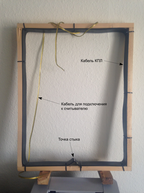
The antenna layout is shown in the following figure.

The internal dimensions of the frame are 400 x 500 mm. Confident reception range - exactly in accordance with the theory, 640 mm along the axis of the antenna for standard markers for livestock. Unsure, which requires additional. processing, extends up to 1.5 m. The
inductance of such a framework is approximately 380 μH.
A certain technological problem is the soldering of the ends of the cable tape. This issue requires the work of a good designer-technologist.
Conclusion
This article discusses the budget way to build the front end of an RFID reader front end according to the ISO 11785 standard.
References
1. High performance low power mixer FM IF system
2. Cable flat elevator KPL
