February 1, 2016 at 06:07
FLProg - Lesson Two: Working with Analog Signals
- Tutorial
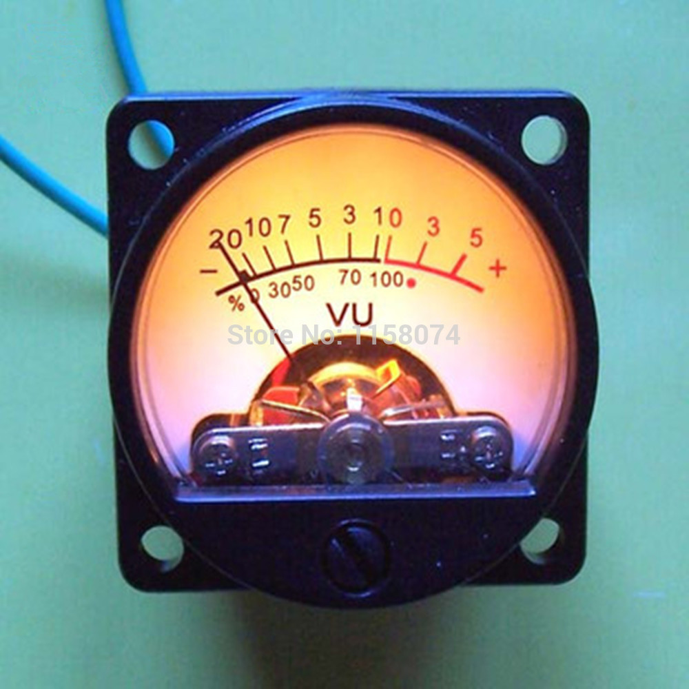
In the previous lesson , the basic principles of working with the FLProg program, as well as working with discrete signals, were described. This lesson will look at FLProg's capabilities for working with analog signals.
During the lesson, a control program for the LED level indicator will be created and the brightness adjustment of the LED using the PWM output will be shown.
Test bench layout.
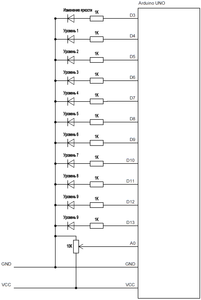
As in the last lesson, we will create the project in two languages FBD and LAD. Only now will it be done in parallel.
Create a new project.
For LAD
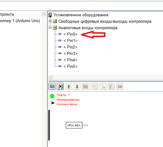
- The first way - we drag the analog input A0 from the tree of installed equipment to the circuit
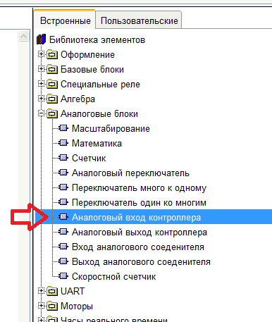
- The second way is to drag the “Analog controller input” block from the element library, and then double-click on the new block and attach it to the zero analog input of the board
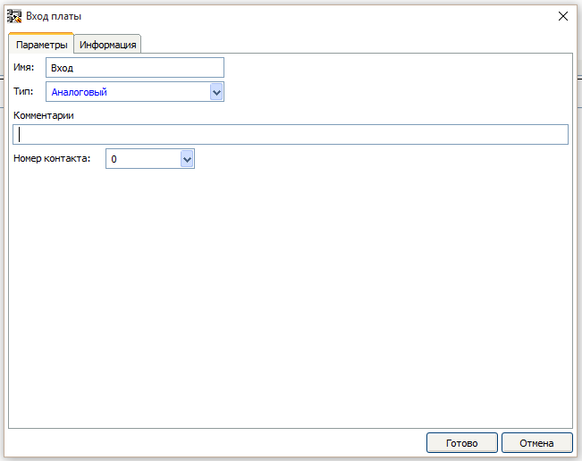
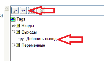
For the FBD language, we create a new analog input by double-clicking on the “Add input” item in the tag tree or by clicking the corresponding button.

In the opened input properties window, enter the input name, select the analog type and contact number 0
Then drag the new input from the tag tree to the circuit area.
The analog input blocks in FLProg at their output give a value proportional to the voltage at the real input of the board attached to them. At 0V at the input of the board, the output of the block will be 0, and at 5V at the input of the board, at the output of the block will be 1023.
Then we create an analog output.
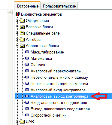
For the LAD language, drag the “Analog output of the controller” block from the library of blocks, and in the property editor of the block (double-click on the block) we attach it to the output of the D3 board.
In the FBD language, to create an analog output, double-click on the “Add output” item in the tag tree or click the appropriate button.
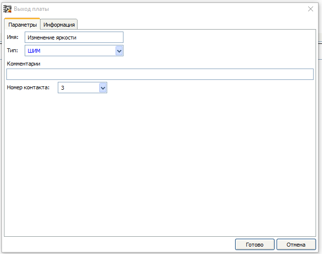
In the output properties window that opens, fill out the name of the output, select the PWM type, and the output number D3.
Then drag the new output to the workspace of the circuit.
Actually, Arduino boards do not have real analog outputs (not counting the Arduino Duo, but so far these boards are not supported by the FLProg program). The analog outputs of the board work in PWM mode.
Pulse width modulation
Pulse Width Modulation (PWM) is the process of controlling the power supplied to a load by changing the duty cycle of the pulses at a constant frequency. For example, you can use the LED as a load.
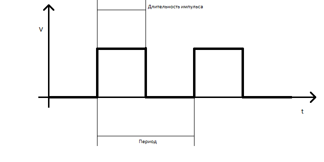
Frequency is the number of periods in one second. Duty rate is the ratio of the pulse duration to the duration of the period. You can change both of them, but to control the LEDs, it is enough to control the duty cycle. In the picture above, we see a PWM signal with a duty cycle of 50%, since the pulse duration (pulse width) is exactly half the period. Accordingly, the LED will be exactly half the time in the on state and half in the off state. The PWM frequency is very large and the eye will not notice the flickering of the LED due to the inertia of our vision, so it will seem to us that the LED is lit at half brightness. If we change the duty cycle by 75%, then the brightness of the LED will be 3 quarters of the full, and the graph will look like this:

It turns out that we can adjust the brightness of the LED from 0 to 100%. Now let's talk about such a PWM parameter as resolution. Resolution is the number of gradations (steps) of duty cycle adjustment. Arduino boards have a resolution of 256 steps.
Frequency is the number of periods in one second. Duty rate is the ratio of the pulse duration to the duration of the period. You can change both of them, but to control the LEDs, it is enough to control the duty cycle. In the picture above, we see a PWM signal with a duty cycle of 50%, since the pulse duration (pulse width) is exactly half the period. Accordingly, the LED will be exactly half the time in the on state and half in the off state. The PWM frequency is very large and the eye will not notice the flickering of the LED due to the inertia of our vision, so it will seem to us that the LED is lit at half brightness. If we change the duty cycle by 75%, then the brightness of the LED will be 3 quarters of the full, and the graph will look like this:
It turns out that we can adjust the brightness of the LED from 0 to 100%. Now let's talk about such a PWM parameter as resolution. Resolution is the number of gradations (steps) of duty cycle adjustment. Arduino boards have a resolution of 256 steps.
In the FLProg program, the analog output unit controls the duty cycle of the PWM output associated with it. When applying a 0 value to the side input, the duty cycle will be 0%, and when a value of 255 is applied, the duty cycle will be 100%.
Based on the fact that the signal limits at the output of the controller analog input block are 0 - 1023 and the limits of the allowable signal at the input of the controller analog output block are 0 - 255, the question arises of whether to bring them to the same value. The scaling unit will help.
In the LAD language, it is located in the “Analog Blocks” folder of the element library.
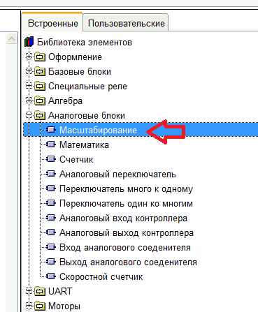
In FBD, the same block is in the Special Blocks folder of the element library.
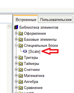
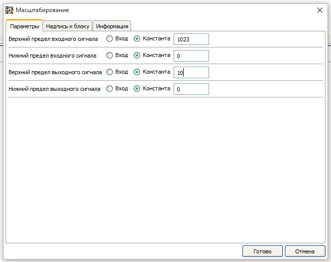
The scaling unit proportionally transfers the value received at the input to a different range of values and outputs this value to the output. The parameters of the input and output ranges of values are set in the block properties. Double-clicking on the block, we can open the block parameter editor and set these values.
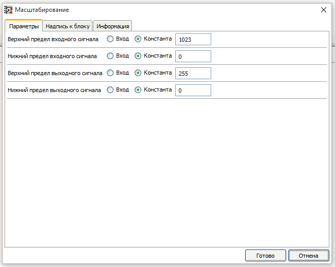
The calculation in the block is performed according to the following formula
Q = (I - I_min) * (Q_max - Q_min) / (I_max - I_min) + Q_min
Where:
- Q - value at the output of the block
- I - value at the input of the block
- I_max - upper limit of the input value
- I_min - lower limit of the input value
- Q_max - upper limit of the output value
- Q_min - lower limit of the output value
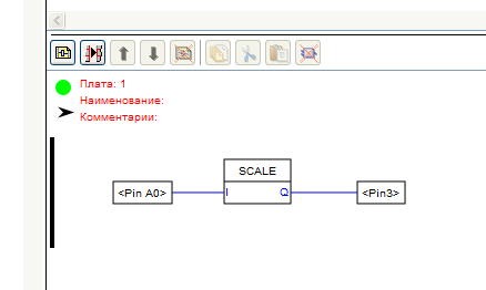
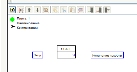
As a result of the block settings shown in the screenshot, when the value at the input of the block changes from 0 to 1023, the value at the output will proportionally change from 0 to 255, which is required. Now you need to connect all the blocks in accordance with the diagram.
LAD
FBD
The first board is almost ready. We call it “Brightness Control” and create a new one, immediately calling it “Level Indicator”
In the second board, we also need the value from the controller input. In principle, you can once again pull out the block input to the second board, and use it. But this will lead to the fact that during the execution of the program in the controller the value from the input will be re-read. And the procedure for reading the analog signal from the input is quite resource-intensive and lengthy. Therefore, we use an analog connector in the case of LAD, and in the case of FBD, a variable.
In FLProg, variable and analog connectors can be represented as terminal connections on the board. Using them, the boards exchange values and connect with each other.
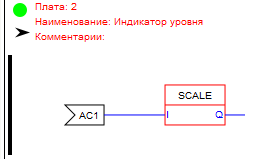
In the LAD project, drag the “Analog Connector Input” block onto the FIRST project board.
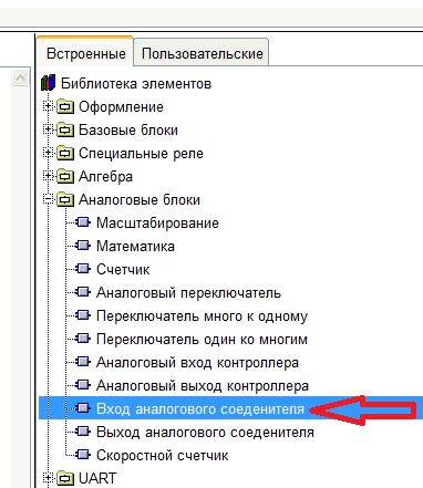
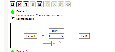
It will automatically be given the name AC1. Then we connect its input to the output of the analog input block.
And onto the second board, drag the “Analog Connector Output” block.
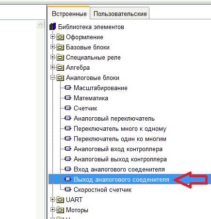
We double click on it and in the block editor bind it to the AC1 connector.
In a project in the FBD language, create a new variable by clicking on the corresponding button or double-clicking on the “Add Variable” item in the tag tree.
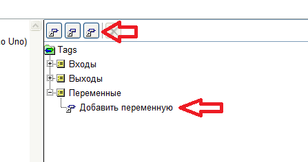
In the opened window of the block editor, fill in the variable name, select the type (Integer), and set the default value - 0
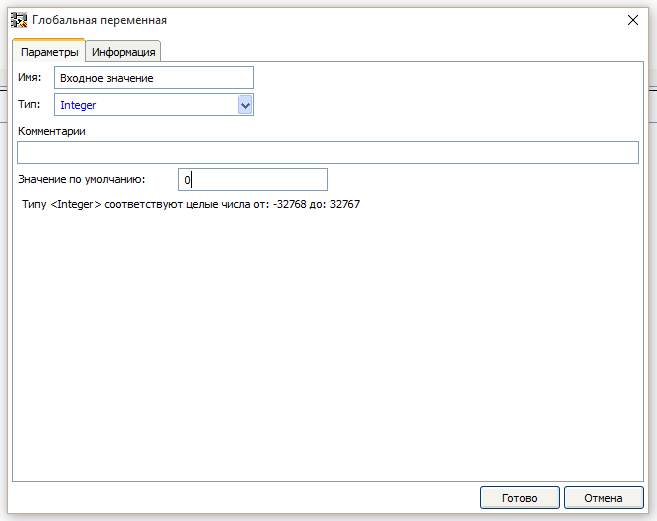
Then we drag the new variable first to one board and then to another. We also connect the variable input to the output of the controller analog input block in the first board.
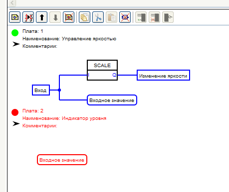
Since the level indicator has 10 values, it is necessary that when changing the value from zero to maximum, the control value should change from zero to 10. The scaling unit will help again. Pull it on the second board and configure it as follows.
Now connect its input in the case of LAD to the output block of the analog connector, and in the case of FBD to the output of the variable.
LAD
FBD
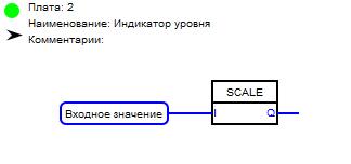
Consider the logic of the level indicator.
- The “Level 1” LED should light up if the signal value is greater than 0
- The “Level 2” LED should light up if the signal value is greater than 1
- The “Level 3” LED should light up if the signal value is greater than 2
- The “Level 4” LED should light up if the signal value is greater than 3
- The “Level 5” LED should light up if the signal value is greater than 4
- The “Level 6” LED should light up if the signal value is greater than 5
- The “Level 7” LED should light up if the signal value is greater than 6
- The “Level 8” LED should light up if the signal value is greater than 7
- The “Level 9” LED should light up if the signal value is greater than 8
- The “Level 10” LED should light up if the signal value is greater than 9
To implement this logic, we use a comparison relay in the case of the LAD language, and a comparator in the case of the FBD language.
LAD
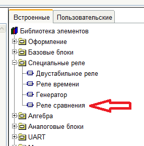
FBD
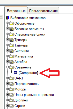
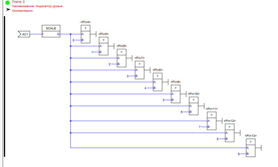
In a project in the LAD language, we pull out 10 comparison relays to the second board and assign them to the outputs to which the level meter is connected ( see the first lesson ) and set the comparison type to “More."
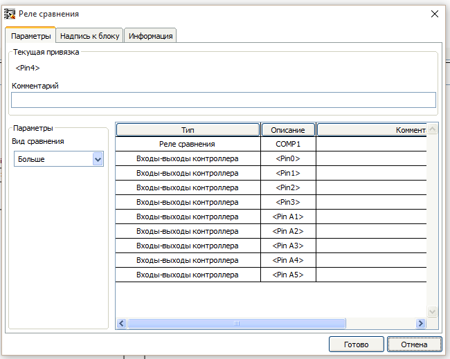
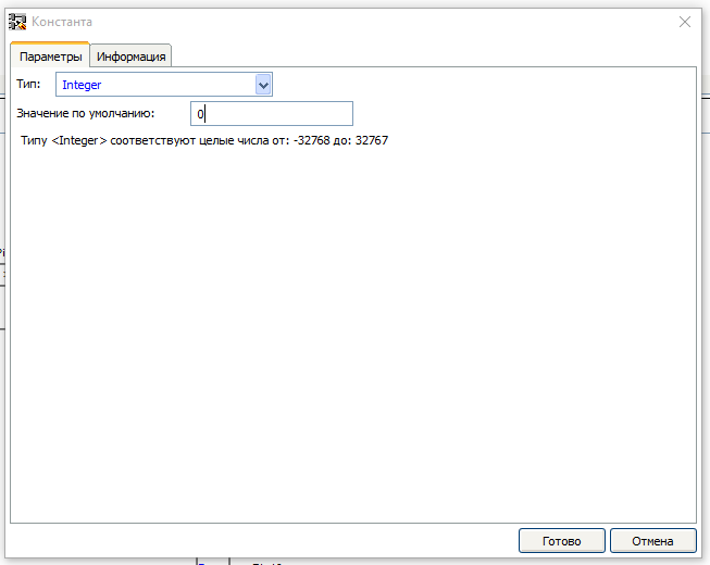
By right-clicking on the input “B” of each block of the comparison relay, we call the context menu and select the item “Insert constant”. In the opened constant editing window, leave the type “Integer” and enter a value for each output that corresponds to the logic of the indicator.
Inputs “A” of all blocks of the comparison relay are connected to the output of the scaling unit. Such a scheme should be obtained.
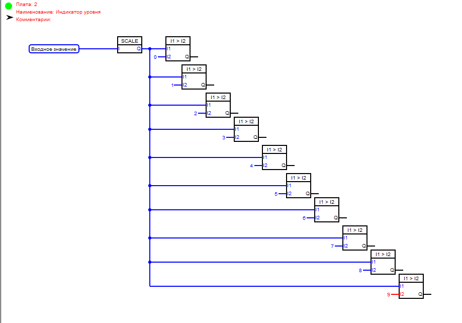
In a project in the FBD language, we pull out 10 Comparator blocks on the second board and set it to the comparison view “More” (double-click on the block to call the block editor). As in LAD-e, we will insert constants on the inputs of I2 blocks, and connect the inputs I1 to the output of the scaling block.
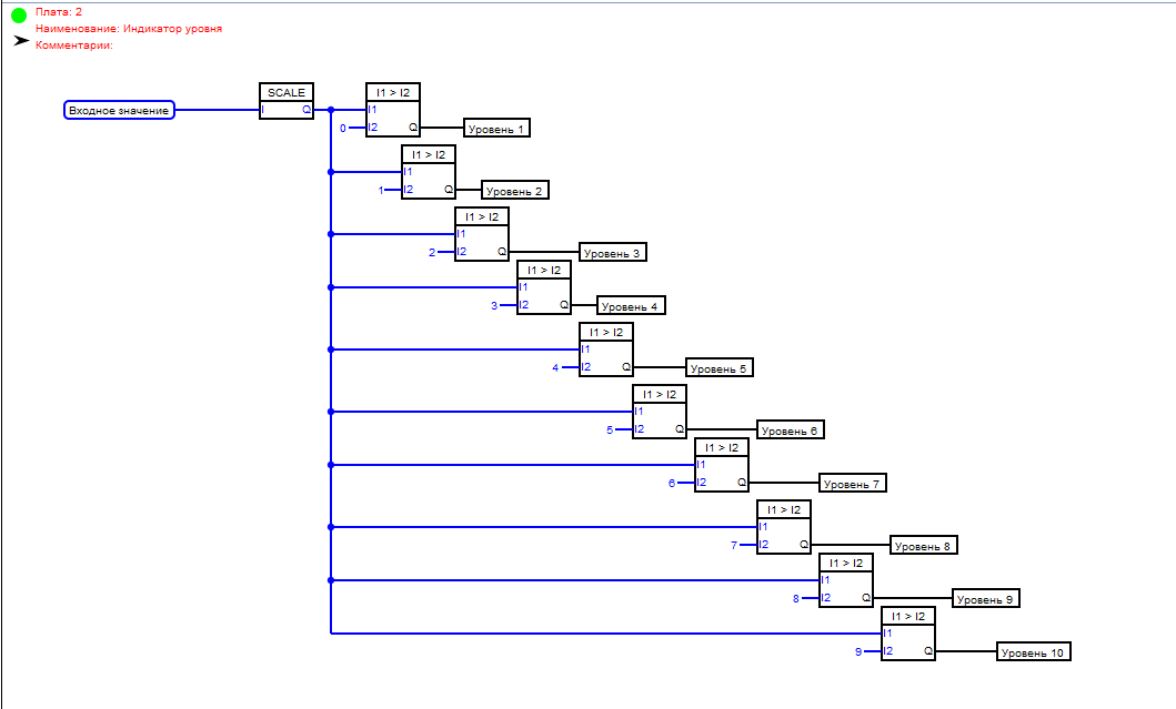
After that, create 10 digital outputs connected to the outputs of the board, to which the level meter is connected (see the first lesson) and pull them to the second board. And we will connect each with its own comparator.
Everything - the programs are ready, you can compile and upload to the controller ( see the first lesson )