Calculation and manufacture of the "heart" IIP - pulse transformer. Part 2
Part 1
And still I was invited! Now, dealing with articles will go more quickly. Initially, I wanted to make the circuitry of some block the theme of the next part, but what should I expect? But then he remembered his school youth and the very great problem faced - how to make the unknown for me at the timeof the beast device - a pulse transformer . Ten years have passed and I understand that many (and not only beginners) radio amateurs, electronic engineers and students have such difficulties - they are simply afraid of them, and as a result they try to avoid powerful switching power supplies (hereinafter IPS ).
After these thoughts, I came to the conclusion that the first topic should be specifically about the transformer and about nothing else! I would also like to make a reservation: what do I mean by the term "powerful IIP" - these are power from 1 kW and above, or in the case of lovers of at least 500 watts.
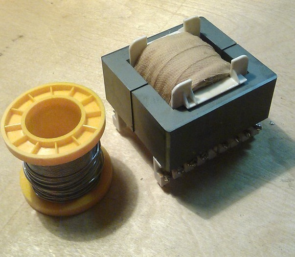
Figure 1 - Here is such a 2 kW transformer for the N-bridge, we get in the end
Having once introduced pulse technology into his arsenal, he thought that transformers can only be made on ferrite that is accessible to everyone. Having collected the first constructions, the first thing I decided to put them to the trial of a more experienced comrade and very often heard the phrase: "Your ferriteshit is not the best material for an impulse . " Immediately I decided to find out from them what kind of alternative can be contrasted with him and they told me - alsifer or as it is called syndast.
First you need to decide what an almost ideal material for the transformer should be able to:
1) it must be magnetically soft , that is, it can be easily magnetized and demagnetized:

Figure 2 - Hysteresis cycles of ferromagnets: 1) hard cycle, 2) soft cycle
2) the material should have as much as possible by induction of saturation, which will allow either to reduce the dimensions of the core, or to increase power while maintaining them.
3) the material should have the least possible losses due to magnetization reversal and Foucault currents
4) the properties of the material should not change much under external influence: mechanical forces (compression or tension), changes in temperature and humidity.
Ferrite is a semiconductor, which means it has its own high electrical resistance. This means that at high frequencies the eddy current loss ( Foucault current ) will be quite low. It turns out at least one of the conditions from the list above has already been fulfilled. We go further ...
Ferrites are thermostable and not stable, but this parameter is not determining for IIP. It is important that ferrites work stably in the temperature range from -60 to +100 о С and this is for the simplest and cheapest brands.

Figure 3 - The magnetization curve at a frequency of 20 kHz at different temperatures.
And finally, the most important point - in the graph above we saw a parameter that will determine almost everything - saturation induction. For ferrite, it is usually taken 0.39 T. It is worth remembering that under different conditions - this parameter will change. It depends on both the frequency and the operating temperature and other parameters, but special emphasis should be placed on the first two.
Conclusion: ferritenishtyak! Great for our tasks.
1) SENDUST works in a little more than a wide temperature range from -60 to +120 and a C - suitable? Better than ferrite!
2) the hysteresis loss coefficient of alsifer is constant only in weak fields (at low power), in a powerful field they grow and very much - this is a very serious minus, especially at powers of more than 2 kW, so it loses.
3) saturation induction up to 1.2 T! 4 times more than ferrite! - the main parameter is already ahead, but not so simple ... Of course, this advantage will not go anywhere, but paragraph 2 weakens it and very much is definitely a plus.
Conclusion: alsifer is better than ferrite, in this uncle they did not lie to me.
Battle Result:anyone reading the description above will say alsifer give us! And rightly so ... but try to find a core made of alsifer and so that with an overall power of 10 kW? Here usually a person comes to a standstill, it turns out they aren’t especially on sale, and if there is, then directly to the manufacturer’s order and the price will scare you.
It turns out that we use ferrite, especially if we evaluate it as a whole, it loses very little ... ferrite is evaluated relative to alsifer in “8 out of 10 parrots”.
I wanted to turn to my favorite matan, but decided not to do this, because +10,000 characters to the article I think is redundant. I can only recommend a book with very good calculations by B. Semenov's authorship “Power Electronics: From Simple to Complex”. I don’t see the point of retelling his calculations with certain additions
The first thing I want to immediately remember a very serious moment - the gap in the core. He can “kill” all power or add 30-40% more. I want to remind you that we are making a transformer for the H-bridge , and it refers to direct-flow converters (forward in bourgeois). This means that the gap should ideally be 0 mm.
Once, in a 2-3-year course, I decided to assemble a welding inverter and turned to the topology of Kemppi inverters. There I saw a 0.15 mm gap in the transformers. It became interesting why he was. He did not approach the teachers, but picked up and called the Russian representative office of Kemppi! What to lose? To my surprise, I was connected to a circuit engineer and he told me some theoretical points that allowed me to "creep out" over the ceiling of 1 kW.
If in short - a gap of 0.1-0.2 mm is simply necessary! This increases the rate of demagnetization of the core, which allows pumping more power through the transformer. The maximum effect of such afeint with the ears of the gap was achieved in the “oblique bridge” topology , where the introduction of a gap of 0.15 mm gives an increase of 100%! In our N-bridge this increase is more modest, but I think 40-60% is not bad either.
For the manufacture of the transformer, we need this kit:
a)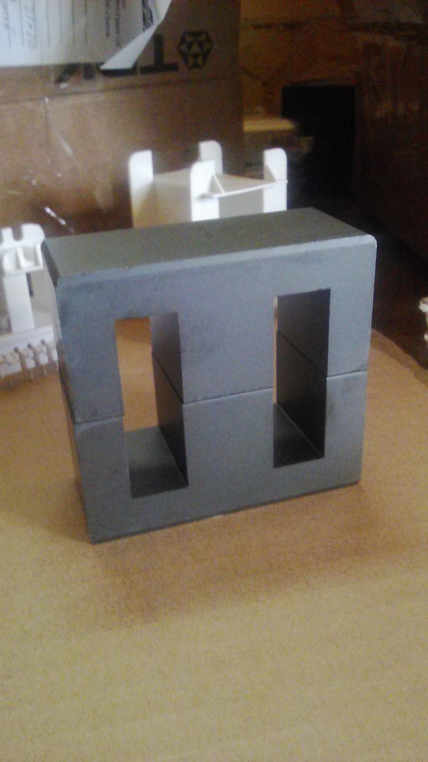
Figure 4 - Ferrite core E70 / 33/32 from 3C90 material (a slightly better analogue of N87)
b)
Figure 5 - Frame for the core E70 / 33/32 (the one that is larger) and the inductor D46 atomized iron
The overall power of such a transformer is 7.2 kW. We need such a margin to provide inrush currents 6-7 times more than the nominal ones (600% in terms of technical specifications). Such starting currents are true only for induction motors, but everything must be taken into account!
Suddenly, a certain choke “surfaced”, it will be needed in our further scheme (as many as 5 pieces) and therefore decided to show how to wind it.
Next, you need to calculate the winding parameters. I use the program from a well-known friend Starichok51 in certain circles . A man with great knowledge and always ready to teach and help, for which he thanks - at one time he helped to get on the right path. The program is called - ExcellentIT 8.1 .
I give an example of calculation for 2 kW:
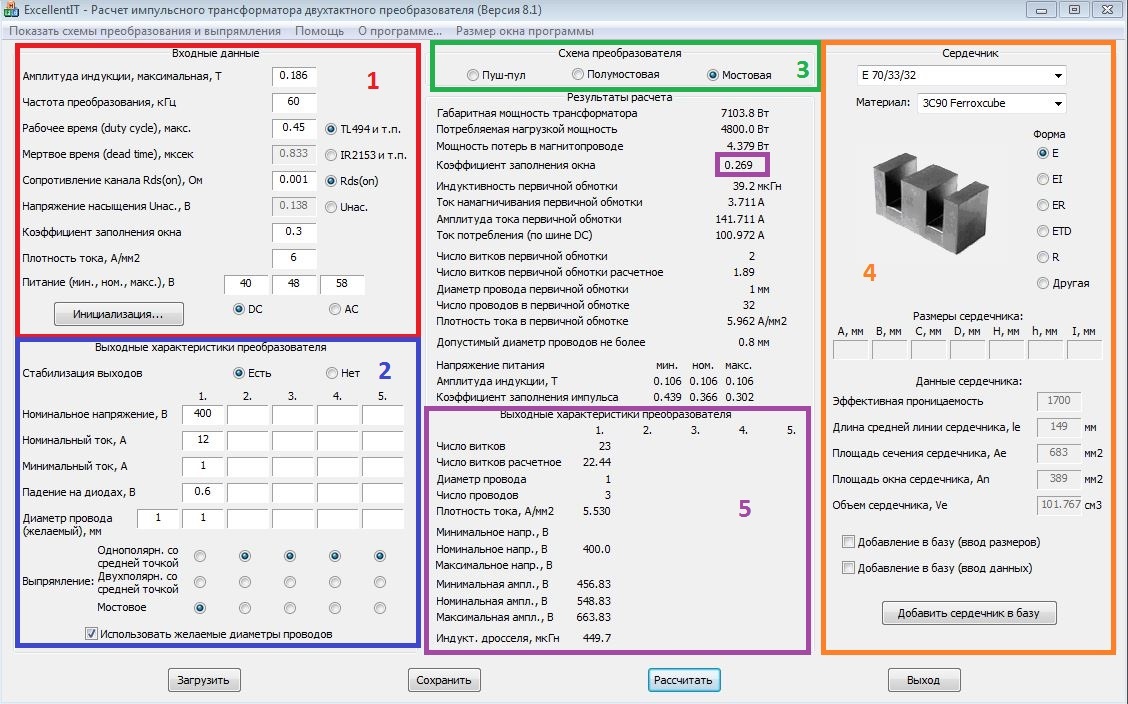
Figure 6 - Calculation of a pulse transformer on a 2 kW bridge circuit increasing
1) Highlighted in red. These are the input parameters that are usually set by default:
a) maximum induction. Remember it is 0.39 T for ferrite, but our transformer operates at a fairly high frequency, so the program sets 0.186 by itself. This is the saturation induction in the worst possible conditions, including heating to 125 degrees
b) the conversion frequency, it is set by us and how it is determined in the diagram will be in the following articles. This frequency should be from 20 to 120 kHz. If less - we will hear the trance and whistle, if higher , then our keys (transistors) will have large dynamic losses. And IGBT keys even expensive work up to 150 kHz
c) coefficient. filling the window is an important parameter, because the space on the frame and core is limited, do not make it larger than 0.35, otherwise the windings will not fit in
d) current density - this parameter can be up to 10 A / mm 2 . This is the maximum current that can flow through a conductor. The optimum value of 5-6 A / mm 2 is in conditions of tough operation: poor cooling, constant operation at full load, and more. 8-10 A / mm 2 - can be set if your device is ideally ventilated and costsover 9000 several coolers.
d) power at the input. Because we calculate the transformer for DC-> DC 48V to 400V, then we set the input voltage as calculated. Where did the figure come from. In the discharged state, the battery gives out 10.5V, then discharge it further - to reduce the service life, multiply by the number of batteries (4 pcs) and we get 42V. Take with a margin of 40V. 48V is taken from the product 12V * 4 pcs. 58V is taken from the consideration that in a charged state the battery has a voltage of 14.2-14.4V and by analogy we multiply by 4.
2) Highlighted in blue.
a) set 400V, because this is a margin for voltage feedback and a minimum of 342V is needed for cutting a sine
b) rated current. For reasons we choose 2400 W / 220 (230) V = 12A. As you can see everywhere I take a margin of at least 20%. Any self-respecting manufacturer of quality equipment does this. In the USSR, such a reserve was a reference 25%, even for the most difficult conditions. Why 220 (230) V is the output voltage of a pure sine.
c) minimum current. Selected from actual conditions, this parameter affects the size of the output inductor, so the greater the minimum current, the smaller the inductor, and therefore cheaper device. Again, I chose the worst case 1A, it’s a current of 2-3 light bulbs or 3-4 routers.
d) drop on diodes. Because we will have ultra-fast diodes at the output, then a drop of 0.6V on them in worse conditions (temperature is exceeded).
d) wire diameter. I once bought a coil of copper of 20 kg for such a case and just with a diameter of 1 mm. Here we put the one that you have. I do not advise you to put more than 1.18 mm, because the skin effect will begin to affect
3) Highlighted in green. Everything is simple here - we plan to have a “full bridge” topology and select it.
4) Highlighted in orange. The core selection process is going on, everything is intuitive. A large number of standard cores are already in the library, like ours, but if you can add something by entering dimensions.
5) Highlighted in purple. Output parameters with calculations. Separate window highlighted coefficient. fill the window, remember - no more than 0.35, and preferably no more than 0.3. All necessary values are also given: the number of turns for the primary and secondary windings, the number of wires of a previously specified diameter in the “braid” for winding.
The parameters for further calculation of the output inductor are also given: inductance and voltage ripple.
Now you need to calculate the output choke. It is needed to smooth out ripples, as well as to create a “uniform” current. The calculation is carried out in the program of the same author and it is called DrosselRing 5.0 . I’ll give the calculation for our transformer:

Figure 7 - Calculation of the output inductor for the boosting DC-DC converter
In this calculation, everything is simpler and more understandable, it works on the same principle, the output is the number of turns and the number of wires in the braid.
Now we have all the data for the manufacture of a transformer and inductor.
The main rule of winding a pulse transformer is that, without exception, all windings must be wound in one direction!
Stage 1:
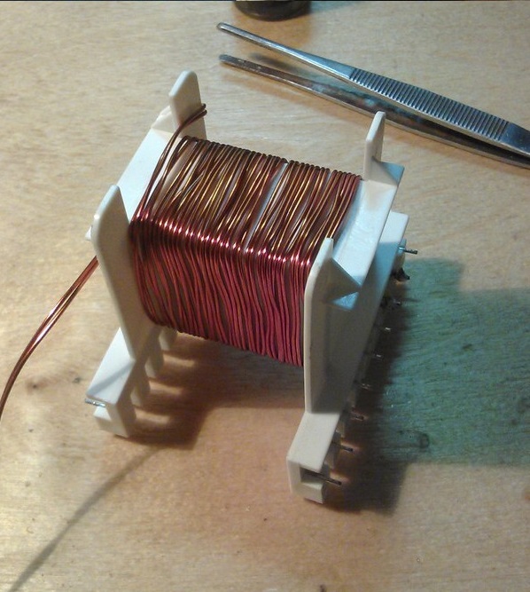
Figure 8 - The process of winding the secondary (high voltage) winding
We wind on the frame the required number of turns in 2 wires with a diameter of 1 mm. We remember the direction of winding, and better mark with a marker on the frame.
Stage 2:

Figure 9 - Insulate the secondary winding
We isolate the secondary winding with a fluoroplastic tape 1 mm thick, this insulation can withstand at least 1000 V. Also, we additionally impregnate with varnish, this is + 600V to the insulation. If there is no fluoroplastic tape, then we isolate with the usual plumbing fum in 4-6 layers. This is the same fluoroplastic, only 150-200 microns thick.
Stage 3:

Figure 10 - We begin to wind the primary winding, unsolder the wires to the frame
Winding is carried out in one direction with the secondary winding!
Stage 4:

Figure 11 - Output the tail of the primary winding
. Winding the winding, isolate it with the same fluoroplastic tape. It is also advisable to soak with varnish.
Stage 5:

Figure 12 - Saturate with varnish and solder the “tail”. Winding finished
Step 6:
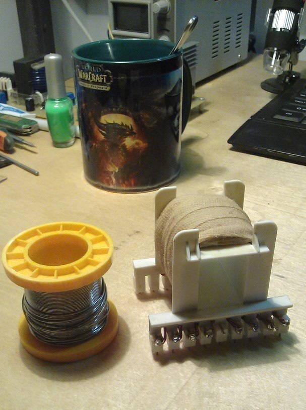
Figure 13 - We complete the winding and isolation of the transformer with a kiper tape with final impregnation in varnish
Stage 7:
Figure 14 - This is how the finished version of the transformer looks. A
0.15 mm gap is set during gluing by inserting a suitable film between the halves of the core. The best option is film for printing. The core sticks together with glue (good moment) or epoxy. The 1st option for centuries, the 2nd allows, in which case, to disassemble the transformer without damage, for example, if you need to wind another winding or add turns.
Now, by analogy, it is necessary to wind the throttle, of course, it is more difficult to wind on the toroidal core, but this option will be more compact. We have all the data from the program, the core material is atomized iron or permalloy. The saturation induction of this material is 0.55 T.
Stage 1:

Figure 15 - Wrap the ring with PTFE tape
This operation avoids the case of breakdown of the winding on the core, this is rare, but we do it for quality!
Stage 2:
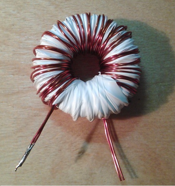
Figure 16 - We wrap the required number of turns and isolate.
In this case, the number of turns does not fit in one winding layer, therefore, after winding the first layer, insulate and wind the second layer with subsequent insulation.
Stage 3:

Figure 17 - Isolate after the second layer and impregnate with varnish
I hope my article will teach you the process of calculating and manufacturing a pulse transformer, as well as give you some theoretical concepts about its operation and the materials from which it is made. I tried not to burden this part with unnecessary theory, everything was at a minimum and focus exclusively on practical points. And most importantly, on key features that affect performance, such as clearance, winding directions and more.
To be continued ...
Part 3
Part 4.1
Part 4.2
Part 5
Part 6
Prologue
And still I was invited! Now, dealing with articles will go more quickly. Initially, I wanted to make the circuitry of some block the theme of the next part, but what should I expect? But then he remembered his school youth and the very great problem faced - how to make the unknown for me at the time
After these thoughts, I came to the conclusion that the first topic should be specifically about the transformer and about nothing else! I would also like to make a reservation: what do I mean by the term "powerful IIP" - these are power from 1 kW and above, or in the case of lovers of at least 500 watts.
Figure 1 - Here is such a 2 kW transformer for the N-bridge, we get in the end
Great battle or what material to choose?
Having once introduced pulse technology into his arsenal, he thought that transformers can only be made on ferrite that is accessible to everyone. Having collected the first constructions, the first thing I decided to put them to the trial of a more experienced comrade and very often heard the phrase: "Your ferrite
Why is it so good and is it really better than ferrite?
First you need to decide what an almost ideal material for the transformer should be able to:
1) it must be magnetically soft , that is, it can be easily magnetized and demagnetized:
Figure 2 - Hysteresis cycles of ferromagnets: 1) hard cycle, 2) soft cycle
2) the material should have as much as possible by induction of saturation, which will allow either to reduce the dimensions of the core, or to increase power while maintaining them.
Saturation
The saturation of the transformer consists in the fact that, despite the increase in current in the winding, the magnetic flux in the core, reaching a certain maximum value, practically does not change further.
In the transformer, the saturation mode leads to the fact that the transfer of energy from the primary to the secondary is partially stopped. Normal operation of the transformer is possible only when the magnetic flux in its core changes in proportion to the change in current in the primary winding. To fulfill this condition, it is necessary that the core is not in a state of saturation, and this is possible only when its volume and cross section is not less than a well-defined value. Therefore, the greater the power of the transformer, the larger should be its core.
In the transformer, the saturation mode leads to the fact that the transfer of energy from the primary to the secondary is partially stopped. Normal operation of the transformer is possible only when the magnetic flux in its core changes in proportion to the change in current in the primary winding. To fulfill this condition, it is necessary that the core is not in a state of saturation, and this is possible only when its volume and cross section is not less than a well-defined value. Therefore, the greater the power of the transformer, the larger should be its core.
3) the material should have the least possible losses due to magnetization reversal and Foucault currents
4) the properties of the material should not change much under external influence: mechanical forces (compression or tension), changes in temperature and humidity.
Now consider the properties of ferrite and how much it meets the above requirements.
Ferrite is a semiconductor, which means it has its own high electrical resistance. This means that at high frequencies the eddy current loss ( Foucault current ) will be quite low. It turns out at least one of the conditions from the list above has already been fulfilled. We go further ...
Ferrites are thermostable and not stable, but this parameter is not determining for IIP. It is important that ferrites work stably in the temperature range from -60 to +100 о С and this is for the simplest and cheapest brands.
Figure 3 - The magnetization curve at a frequency of 20 kHz at different temperatures.
And finally, the most important point - in the graph above we saw a parameter that will determine almost everything - saturation induction. For ferrite, it is usually taken 0.39 T. It is worth remembering that under different conditions - this parameter will change. It depends on both the frequency and the operating temperature and other parameters, but special emphasis should be placed on the first two.
Conclusion: ferrite
A few words about alsifer and how it differs
1) SENDUST works in a little more than a wide temperature range from -60 to +120 and a C - suitable? Better than ferrite!
2) the hysteresis loss coefficient of alsifer is constant only in weak fields (at low power), in a powerful field they grow and very much - this is a very serious minus, especially at powers of more than 2 kW, so it loses.
3) saturation induction up to 1.2 T! 4 times more than ferrite! - the main parameter is already ahead, but not so simple ... Of course, this advantage will not go anywhere, but paragraph 2 weakens it and very much is definitely a plus.
Conclusion: alsifer is better than ferrite, in this uncle they did not lie to me.
Battle Result:anyone reading the description above will say alsifer give us! And rightly so ... but try to find a core made of alsifer and so that with an overall power of 10 kW? Here usually a person comes to a standstill, it turns out they aren’t especially on sale, and if there is, then directly to the manufacturer’s order and the price will scare you.
It turns out that we use ferrite, especially if we evaluate it as a whole, it loses very little ... ferrite is evaluated relative to alsifer in “8 out of 10 parrots”.
I wanted to turn to my favorite matan, but decided not to do this, because +10,000 characters to the article I think is redundant. I can only recommend a book with very good calculations by B. Semenov's authorship “Power Electronics: From Simple to Complex”. I don’t see the point of retelling his calculations with certain additions
So, we proceed to the calculation and manufacture of the transformer
The first thing I want to immediately remember a very serious moment - the gap in the core. He can “kill” all power or add 30-40% more. I want to remind you that we are making a transformer for the H-bridge , and it refers to direct-flow converters (forward in bourgeois). This means that the gap should ideally be 0 mm.
Once, in a 2-3-year course, I decided to assemble a welding inverter and turned to the topology of Kemppi inverters. There I saw a 0.15 mm gap in the transformers. It became interesting why he was. He did not approach the teachers, but picked up and called the Russian representative office of Kemppi! What to lose? To my surprise, I was connected to a circuit engineer and he told me some theoretical points that allowed me to "creep out" over the ceiling of 1 kW.
If in short - a gap of 0.1-0.2 mm is simply necessary! This increases the rate of demagnetization of the core, which allows pumping more power through the transformer. The maximum effect of such a
For the manufacture of the transformer, we need this kit:
a)
Figure 4 - Ferrite core E70 / 33/32 from 3C90 material (a slightly better analogue of N87)
b)
Figure 5 - Frame for the core E70 / 33/32 (the one that is larger) and the inductor D46 atomized iron
The overall power of such a transformer is 7.2 kW. We need such a margin to provide inrush currents 6-7 times more than the nominal ones (600% in terms of technical specifications). Such starting currents are true only for induction motors, but everything must be taken into account!
Suddenly, a certain choke “surfaced”, it will be needed in our further scheme (as many as 5 pieces) and therefore decided to show how to wind it.
Next, you need to calculate the winding parameters. I use the program from a well-known friend Starichok51 in certain circles . A man with great knowledge and always ready to teach and help, for which he thanks - at one time he helped to get on the right path. The program is called - ExcellentIT 8.1 .
I give an example of calculation for 2 kW:
Figure 6 - Calculation of a pulse transformer on a 2 kW bridge circuit increasing
How to calculate:
1) Highlighted in red. These are the input parameters that are usually set by default:
a) maximum induction. Remember it is 0.39 T for ferrite, but our transformer operates at a fairly high frequency, so the program sets 0.186 by itself. This is the saturation induction in the worst possible conditions, including heating to 125 degrees
b) the conversion frequency, it is set by us and how it is determined in the diagram will be in the following articles. This frequency should be from 20 to 120 kHz. If less - we will hear the trance and whistle, if higher , then our keys (transistors) will have large dynamic losses. And IGBT keys even expensive work up to 150 kHz
c) coefficient. filling the window is an important parameter, because the space on the frame and core is limited, do not make it larger than 0.35, otherwise the windings will not fit in
d) current density - this parameter can be up to 10 A / mm 2 . This is the maximum current that can flow through a conductor. The optimum value of 5-6 A / mm 2 is in conditions of tough operation: poor cooling, constant operation at full load, and more. 8-10 A / mm 2 - can be set if your device is ideally ventilated and costs
d) power at the input. Because we calculate the transformer for DC-> DC 48V to 400V, then we set the input voltage as calculated. Where did the figure come from. In the discharged state, the battery gives out 10.5V, then discharge it further - to reduce the service life, multiply by the number of batteries (4 pcs) and we get 42V. Take with a margin of 40V. 48V is taken from the product 12V * 4 pcs. 58V is taken from the consideration that in a charged state the battery has a voltage of 14.2-14.4V and by analogy we multiply by 4.
2) Highlighted in blue.
a) set 400V, because this is a margin for voltage feedback and a minimum of 342V is needed for cutting a sine
b) rated current. For reasons we choose 2400 W / 220 (230) V = 12A. As you can see everywhere I take a margin of at least 20%. Any self-respecting manufacturer of quality equipment does this. In the USSR, such a reserve was a reference 25%, even for the most difficult conditions. Why 220 (230) V is the output voltage of a pure sine.
c) minimum current. Selected from actual conditions, this parameter affects the size of the output inductor, so the greater the minimum current, the smaller the inductor, and therefore cheaper device. Again, I chose the worst case 1A, it’s a current of 2-3 light bulbs or 3-4 routers.
d) drop on diodes. Because we will have ultra-fast diodes at the output, then a drop of 0.6V on them in worse conditions (temperature is exceeded).
d) wire diameter. I once bought a coil of copper of 20 kg for such a case and just with a diameter of 1 mm. Here we put the one that you have. I do not advise you to put more than 1.18 mm, because the skin effect will begin to affect
Skin effect
Skin effect - the effect of decreasing the amplitude of electromagnetic waves as they penetrate deeper into the conducting medium. As a result of this effect, for example, an alternating current of high frequency when flowing through a conductor is distributed not uniformly over the cross section, but mainly in the surface layer.
If you speak not like Google, but with my collective farm language, then if you take a large cross-section conductor, it will not be used completely, because currents at a higher frequency flow along the surface, and the center of the conductor will be "empty"
If you speak not like Google, but with my collective farm language, then if you take a large cross-section conductor, it will not be used completely, because currents at a higher frequency flow along the surface, and the center of the conductor will be "empty"
3) Highlighted in green. Everything is simple here - we plan to have a “full bridge” topology and select it.
4) Highlighted in orange. The core selection process is going on, everything is intuitive. A large number of standard cores are already in the library, like ours, but if you can add something by entering dimensions.
5) Highlighted in purple. Output parameters with calculations. Separate window highlighted coefficient. fill the window, remember - no more than 0.35, and preferably no more than 0.3. All necessary values are also given: the number of turns for the primary and secondary windings, the number of wires of a previously specified diameter in the “braid” for winding.
The parameters for further calculation of the output inductor are also given: inductance and voltage ripple.
Now you need to calculate the output choke. It is needed to smooth out ripples, as well as to create a “uniform” current. The calculation is carried out in the program of the same author and it is called DrosselRing 5.0 . I’ll give the calculation for our transformer:
Figure 7 - Calculation of the output inductor for the boosting DC-DC converter
In this calculation, everything is simpler and more understandable, it works on the same principle, the output is the number of turns and the number of wires in the braid.
Stages of manufacture
Now we have all the data for the manufacture of a transformer and inductor.
The main rule of winding a pulse transformer is that, without exception, all windings must be wound in one direction!
Stage 1:
Figure 8 - The process of winding the secondary (high voltage) winding
We wind on the frame the required number of turns in 2 wires with a diameter of 1 mm. We remember the direction of winding, and better mark with a marker on the frame.
Stage 2:
Figure 9 - Insulate the secondary winding
We isolate the secondary winding with a fluoroplastic tape 1 mm thick, this insulation can withstand at least 1000 V. Also, we additionally impregnate with varnish, this is + 600V to the insulation. If there is no fluoroplastic tape, then we isolate with the usual plumbing fum in 4-6 layers. This is the same fluoroplastic, only 150-200 microns thick.
Stage 3:
Figure 10 - We begin to wind the primary winding, unsolder the wires to the frame
Winding is carried out in one direction with the secondary winding!
Stage 4:
Figure 11 - Output the tail of the primary winding
. Winding the winding, isolate it with the same fluoroplastic tape. It is also advisable to soak with varnish.
Stage 5:
Figure 12 - Saturate with varnish and solder the “tail”. Winding finished
Step 6:
Figure 13 - We complete the winding and isolation of the transformer with a kiper tape with final impregnation in varnish
Kiper tape
Kiper tape - cotton (less often silk or semi-silk) braid made of kiper fabric from 8 to 50 mm wide, twill or diagonal weave; severe, bleached or one-colored. The material of the tape is characterized by high density due to weaving, it is thicker than that of its closest analogue - calico tape - due to the use of thicker threads.
Thanks wikipedia.
Thanks wikipedia.
Stage 7:
Figure 14 - This is how the finished version of the transformer looks. A
0.15 mm gap is set during gluing by inserting a suitable film between the halves of the core. The best option is film for printing. The core sticks together with glue (good moment) or epoxy. The 1st option for centuries, the 2nd allows, in which case, to disassemble the transformer without damage, for example, if you need to wind another winding or add turns.
Throttle winding
Now, by analogy, it is necessary to wind the throttle, of course, it is more difficult to wind on the toroidal core, but this option will be more compact. We have all the data from the program, the core material is atomized iron or permalloy. The saturation induction of this material is 0.55 T.
Stage 1:
Figure 15 - Wrap the ring with PTFE tape
This operation avoids the case of breakdown of the winding on the core, this is rare, but we do it for quality!
Stage 2:
Figure 16 - We wrap the required number of turns and isolate.
In this case, the number of turns does not fit in one winding layer, therefore, after winding the first layer, insulate and wind the second layer with subsequent insulation.
Stage 3:
Figure 17 - Isolate after the second layer and impregnate with varnish
Epilogue
I hope my article will teach you the process of calculating and manufacturing a pulse transformer, as well as give you some theoretical concepts about its operation and the materials from which it is made. I tried not to burden this part with unnecessary theory, everything was at a minimum and focus exclusively on practical points. And most importantly, on key features that affect performance, such as clearance, winding directions and more.
To be continued ...
Part 3
Part 4.1
Part 4.2
Part 5
Part 6