Learning the MBR and GPT Structures
To work with a hard disk, you first need to mark it up somehow so that the operating system can understand in which areas of the disk you can write information. Since hard disks are large, their space is usually divided into several parts - disk partitions. Each such partition can be assigned its own drive letter (for systems of the Windows family) and you can work with it as if it were an independent drive in the system.
There are two ways to partition disks today. The first way is to use MBR. This method has been used almost since the advent of hard drives and works with any operating systems. The second way is to use the new markup system - GPT. This method is supported only by modern operating systems, since it is still relatively young.
Until recently, the MBR structure was used on all personal computers in order to be able to divide one large physical hard disk (HDD) into several logical parts - disk partitions (partition). Currently, the MBR is being actively superseded by a new partitioning structure - GPT (GUID Partition Table). However, MBR is still used quite widely, so let's see what it is.
MBR is always in the first sector of the hard drive. When the computer boots, the BIOS reads this sector from disk to memory at the address 0000: 7C00h and transfers control to it.
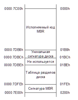
So, the first section of the MBR structure is a section with executable code, which will guide the further download. The size of this section can be a maximum of 440 bytes. Next come 4 bytes reserved for disk identification. In operating systems where identification is not used, executable code may occupy this place. The same goes for the next 2 bytes.
Starting at offset 01BEh, the partition table itself is located. The table consists of 4 records (one for each possible disk partition) of 16 bytes in size.
Record structure for one section:
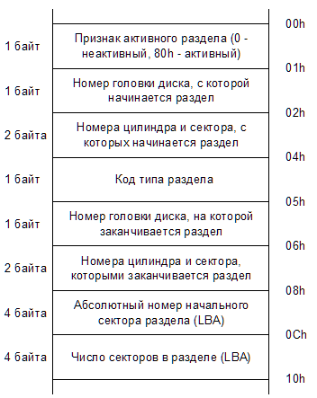
The first byte in this structure is a sign of partition activity. This symptom determines from which section the download should continue. There can only be one active partition, otherwise the download will not continue.
The next three bytes are the so-called CHS coordinates of the first section sector.
At offset 04h is the section type code. It is by this type that you can determine what is in this section, what file system is on it, etc. A list of reserved section types can be viewed, for example, on Wikipedia using the Section types link .
After the type of section, 3 bytes follow, defining the CHS-coordinates of the last sector of the section.
So, currently LBA-addressing is widely used for sectors on the disk and in the structure of the partition record the address of its first sector is written at offset 08h, and the size of the partition is written at offset 0Ch.
For disks up to 8GB in size (when CHS addressing is still possible), the structure fields with CHS coordinates and LBA addresses must correspond to each other in value (correctly convert from one format to another). For drives larger than 8 GB, the values of all three bytes of the CHS-coordinates should be equal to FFh (for the head, the FEh value is also allowed).
At the end of the MBR structure is always the AA55h signature. To some extent, it allows you to verify that the MBR sector is not damaged and contains the necessary data.
Partitions marked with 05h and 0Fh in the table are the so-called extended partitions. With their help, you can create more partitions on the disk than the MBR allows. In fact, there are several more extended partitions, for example, there are partitions with types C5h, 15h, 1Fh, 91h, 9Bh, 85h. Basically, all these types of partitions were used at one time by various operating systems (such as OS / 2, DR-DOS, FreeDOS) for the same purpose - to increase the number of partitions on a disk. However, over time, various formats disappeared and only sections with types 05h and 0Fh remained. The only exception is type 85h. It can still be used on Linux to form a second chain of logical drives hidden from other operating systems. Partitions of type 05h are used for drives less than 8GB (where addressing via CHS is still possible),
The first sector of the extended partition contains the EBR (Extended Boot Record) structure. It is largely similar to the MBR structure, but has the following differences:
At the end of the EBR structure, as well as in the MBR, there should be a “magic” value AA55h.
Unlike MBR, where it is allowed to create no more than four partitions, the EBR structure allows you to organize a list of logical partitions, limited only by the size of the container section (the same one with type 05h or 0Fh). To organize such a list, the following record format is used: the first record in the EBR partition table indicates the logical partition associated with this EBR, and the second record indicates the next EBR partition in the list. If this logical partition is the last in the list, then the second entry in the EBR partition table must be filled with zeros.

The format of the section records in the EBR is similar to the format of the records in the MBR structure, but logically it is slightly different.
The partition activity indicator for sections of the EBR structure will always be 0, since loading was carried out only from the main disk partitions. The CHS coordinates from which the section begins are used if LBA addressing is not involved, as well as in the MBR structure.
But the fields where the number of the initial sector and the number of sectors of the section should be in the LBA addressing mode are used slightly differently in the EBR structure.

For the first record of the EBR partition table, the distance in the sectors between the current EBR sector and the beginning of the logical partition referenced by the record is recorded in the field of the initial sector of the section (offset 08h). In the field of the number of sectors of the partition (offset 0Ch) in this case, the size of this logical partition in the sectors is written.
For the second entry in the EBR section table, the distance between the sector of the very first EBR and the sector of the next EBR in the list is recorded in the field of the initial sector of the section. In this case, the size of the disk area from the sector of this next EBR structure to the end of the logical partition related to this structure is written in the field of the number of sectors of the partition.
Thus, the first record of the partition table describes how to find and what size the current logical partition occupies, and the second record describes how to find and what size the next EBR in the list occupies, together with its partition.
In modern computers, the BIOS was replaced by the new UEFI specification, and with it the new partition device on the hard disk - the GUID Partition Table (GPT). In this structure, all the shortcomings and limitations imposed by the MBR were taken into account, and it was developed with a large margin for the future.
The GPT structure now uses only LBA addressing, there are no more CHS and no problems with their conversion either. Moreover, 64 bits are allocated for LBA addresses, which allows you to work with them without any tricks, like with 64-bit integers, and also (if it comes to that) will make it possible in the future to expand the 48-bit LBA addressing to 64 without problems bit.
In addition, unlike MBR, the GPT structure stores two of its copies on the disk, one at the beginning of the disk and the other at the end. Thus, in case of damage to the main structure, it will be possible to restore it from a saved copy.
Let us now consider the structure of the GPT in more detail. The entire structure of the GPT on the hard disk consists of 6 parts:
The first sector on the disk (with LBA address 0) is the same MBR sector. It was left for compatibility with old software and is designed to protect the GPT structure from accidental damage when working with programs that do not know anything about GPT. For such programs, the partition structure will look like one partition, which takes up all the space on the hard drive.
The structure of this sector is no different from the regular MBR sector. A single entry with a partition type of 0xEE must be created in its partition table. The section must begin with the address LBA 1 and have a size of 0xFFFFFFFF. In the fields for CHS-addressing, the section should accordingly start with the address 0/0/2 (sector 1 is occupied by the MBR itself) and have the final CHS-address FF / FF / FF. The attribute of the active section must be set to 0 (inactive).
When a computer is running UEFI, this MBR sector is simply ignored and no code is executed in it either.
This header sector contains data on all LBA addresses used to partition the disk.
GPT header structure:
The UEFI system verifies the correctness of the GPT header using checksums calculated using the CRC32 algorithm. If the primary header is damaged, then the checksum of the copy of the header is checked. If the checksum of the header copy is correct, then this copy is used to restore the information in the primary header. Recovery also occurs in the opposite direction - if the primary header is correct and the copy is incorrect, then the copy is restored from the data from the primary header. If both copies of the header are damaged, then the disk becomes inaccessible to work.
The partition table additionally has its own checksum, which is written in the header at offset 0x58. When changing the data in the partition table, this amount is recalculated and updated in the primary header and in its copy, and then the checksum of the GPT headers themselves is calculated and updated.
The next part of the GPT structure is the partition table itself. Currently, Windows and Linux operating systems use the same partition table format - a maximum of 128 partitions, 128 bytes are allocated for each partition entry, respectively, the entire partition table will occupy 128 * 128 = 16384 bytes, or 32 disk sectors.
Section Record Format:
Section attributes written at offset 0x30 can have the following bit values:
With the remaining parts of the markup, everything is clear without a detailed description. The content of the sections speaks for itself. Copy of the partition table - also understandable, stores a copy of the partition table. Well, the last sector of the disk is a copy of the GPT header.
There are two ways to partition disks today. The first way is to use MBR. This method has been used almost since the advent of hard drives and works with any operating systems. The second way is to use the new markup system - GPT. This method is supported only by modern operating systems, since it is still relatively young.
MBR structure
Until recently, the MBR structure was used on all personal computers in order to be able to divide one large physical hard disk (HDD) into several logical parts - disk partitions (partition). Currently, the MBR is being actively superseded by a new partitioning structure - GPT (GUID Partition Table). However, MBR is still used quite widely, so let's see what it is.
MBR is always in the first sector of the hard drive. When the computer boots, the BIOS reads this sector from disk to memory at the address 0000: 7C00h and transfers control to it.
So, the first section of the MBR structure is a section with executable code, which will guide the further download. The size of this section can be a maximum of 440 bytes. Next come 4 bytes reserved for disk identification. In operating systems where identification is not used, executable code may occupy this place. The same goes for the next 2 bytes.
Starting at offset 01BEh, the partition table itself is located. The table consists of 4 records (one for each possible disk partition) of 16 bytes in size.
Record structure for one section:
The first byte in this structure is a sign of partition activity. This symptom determines from which section the download should continue. There can only be one active partition, otherwise the download will not continue.
The next three bytes are the so-called CHS coordinates of the first section sector.
At offset 04h is the section type code. It is by this type that you can determine what is in this section, what file system is on it, etc. A list of reserved section types can be viewed, for example, on Wikipedia using the Section types link .
After the type of section, 3 bytes follow, defining the CHS-coordinates of the last sector of the section.
The CHS coordinates of the sector are deciphered as the Cylinder Head Sector and accordingly indicate the cylinder (track) number, head (surface) number and sector number. Cylinders and heads are numbered from scratch, the sector is numbered from one. Thus, CHS = 0/0/1 means the first sector on the zero cylinder on the zero head. This is where the MBR sector is located.The problem with CHS coordinates is that with this record you can address a maximum of 8 GB of disk. In the DOS era, this was acceptable, but pretty soon it was no longer enough. To solve this problem, a Logical Block Addressing (LBA) system was developed that used flat 32-bit disk sector numbering. This made it possible to address disks up to 2 TB in size. Later, the bit capacity of the LBA was increased to 48 bits, however, the MBR did not affect these changes. It still has 32-bit sector addressing.
All sections of the disk, with the exception of the first, usually begin with a zero head and the first sector of a cylinder. That is, their address will be N / 0/1. The first partition of the disk begins with head 1, that is, at 0/1/1. This is all due to the fact that at the zero head place is already taken by the MBR sector. Thus, between the MBR sector and the beginning of the first section there are always additional unused 62 sectors. Some OS loaders use them for their needs.
An interesting format for storing cylinder numbers and sectors in the structure of a section record. The cylinder number and sector number are divided by two bytes, but not equally, but like 10: 6. That is, the sector number has the lower 6 bits of the low byte, which allows you to set the sector numbers from 1 to 63. And the cylinder number is allocated 10 bits - 8 bits of the high byte and the remaining 2 bits from the low byte: "CCCCCCCC CCSSSSSS", and in the low Byte are the most significant bits of the cylinder number.
So, currently LBA-addressing is widely used for sectors on the disk and in the structure of the partition record the address of its first sector is written at offset 08h, and the size of the partition is written at offset 0Ch.
For disks up to 8GB in size (when CHS addressing is still possible), the structure fields with CHS coordinates and LBA addresses must correspond to each other in value (correctly convert from one format to another). For drives larger than 8 GB, the values of all three bytes of the CHS-coordinates should be equal to FFh (for the head, the FEh value is also allowed).
At the end of the MBR structure is always the AA55h signature. To some extent, it allows you to verify that the MBR sector is not damaged and contains the necessary data.
Extended sections
Partitions marked with 05h and 0Fh in the table are the so-called extended partitions. With their help, you can create more partitions on the disk than the MBR allows. In fact, there are several more extended partitions, for example, there are partitions with types C5h, 15h, 1Fh, 91h, 9Bh, 85h. Basically, all these types of partitions were used at one time by various operating systems (such as OS / 2, DR-DOS, FreeDOS) for the same purpose - to increase the number of partitions on a disk. However, over time, various formats disappeared and only sections with types 05h and 0Fh remained. The only exception is type 85h. It can still be used on Linux to form a second chain of logical drives hidden from other operating systems. Partitions of type 05h are used for drives less than 8GB (where addressing via CHS is still possible),
The first sector of the extended partition contains the EBR (Extended Boot Record) structure. It is largely similar to the MBR structure, but has the following differences:
- There is no executable code in EBR. Some loaders can write it there, but usually this place is filled with zeros
- Disk signatures and two unused bytes must be filled with zeros
- Only the first two entries can be filled in the partition table. The remaining two entries must be filled with zeros
At the end of the EBR structure, as well as in the MBR, there should be a “magic” value AA55h.
Unlike MBR, where it is allowed to create no more than four partitions, the EBR structure allows you to organize a list of logical partitions, limited only by the size of the container section (the same one with type 05h or 0Fh). To organize such a list, the following record format is used: the first record in the EBR partition table indicates the logical partition associated with this EBR, and the second record indicates the next EBR partition in the list. If this logical partition is the last in the list, then the second entry in the EBR partition table must be filled with zeros.
The format of the section records in the EBR is similar to the format of the records in the MBR structure, but logically it is slightly different.
The partition activity indicator for sections of the EBR structure will always be 0, since loading was carried out only from the main disk partitions. The CHS coordinates from which the section begins are used if LBA addressing is not involved, as well as in the MBR structure.
But the fields where the number of the initial sector and the number of sectors of the section should be in the LBA addressing mode are used slightly differently in the EBR structure.
For the first record of the EBR partition table, the distance in the sectors between the current EBR sector and the beginning of the logical partition referenced by the record is recorded in the field of the initial sector of the section (offset 08h). In the field of the number of sectors of the partition (offset 0Ch) in this case, the size of this logical partition in the sectors is written.
For the second entry in the EBR section table, the distance between the sector of the very first EBR and the sector of the next EBR in the list is recorded in the field of the initial sector of the section. In this case, the size of the disk area from the sector of this next EBR structure to the end of the logical partition related to this structure is written in the field of the number of sectors of the partition.
Thus, the first record of the partition table describes how to find and what size the current logical partition occupies, and the second record describes how to find and what size the next EBR in the list occupies, together with its partition.
GPT structure
In modern computers, the BIOS was replaced by the new UEFI specification, and with it the new partition device on the hard disk - the GUID Partition Table (GPT). In this structure, all the shortcomings and limitations imposed by the MBR were taken into account, and it was developed with a large margin for the future.
The GPT structure now uses only LBA addressing, there are no more CHS and no problems with their conversion either. Moreover, 64 bits are allocated for LBA addresses, which allows you to work with them without any tricks, like with 64-bit integers, and also (if it comes to that) will make it possible in the future to expand the 48-bit LBA addressing to 64 without problems bit.
In addition, unlike MBR, the GPT structure stores two of its copies on the disk, one at the beginning of the disk and the other at the end. Thus, in case of damage to the main structure, it will be possible to restore it from a saved copy.
Let us now consider the structure of the GPT in more detail. The entire structure of the GPT on the hard disk consists of 6 parts:
| LBA address | Size (sectors) | Appointment |
| LBA 0 | 1 | Security MBR Sector |
| LBA 1 | 1 | Primary GPT Header |
| LBA 2 | 32 | Disk partition table |
| LBA 34 | Nn | Disk Partition Content |
| LBA -34 | 32 | Copy of the partition table |
| LBA -2 | 1 | Copy GPT Header |
Security MBR Sector
The first sector on the disk (with LBA address 0) is the same MBR sector. It was left for compatibility with old software and is designed to protect the GPT structure from accidental damage when working with programs that do not know anything about GPT. For such programs, the partition structure will look like one partition, which takes up all the space on the hard drive.
The structure of this sector is no different from the regular MBR sector. A single entry with a partition type of 0xEE must be created in its partition table. The section must begin with the address LBA 1 and have a size of 0xFFFFFFFF. In the fields for CHS-addressing, the section should accordingly start with the address 0/0/2 (sector 1 is occupied by the MBR itself) and have the final CHS-address FF / FF / FF. The attribute of the active section must be set to 0 (inactive).
When a computer is running UEFI, this MBR sector is simply ignored and no code is executed in it either.
Primary GPT Header
This header sector contains data on all LBA addresses used to partition the disk.
GPT header structure:
| Offset (byte) | Field Size (Bytes) | Filling example | Field Name and Description |
| 0x00 | 8 bytes | 45 46 49 20 50 41 52 54 | The signature of the header. Used to identify all EFI-compatible GPT headers. It should contain the value 45 46 49 20 50 41 52 54, which in the form of text stands for "EFI PART". |
| 0x08 | 4 bytes | 00 00 01 00 | Header format version (not UEFI specification). Header version 1.0 is currently in use. |
| 0x0C | 4 bytes | 5C 00 00 00 | GPT header size in bytes. Matches 0x5C (92 bytes) |
| 0x10 | 4 bytes | 27 6D 9F C9 | The checksum of the GPT header (at addresses from 0x00 to 0x5C). The checksum algorithm is CRC32. When calculating the checksum, the initial value of this field is taken equal to zero. |
| 0x14 | 4 bytes | 00 00 00 00 | Reserved. Must have a value of 0 |
| 0x18 | 8 bytes | 01 00 00 00 00 00 00 00 00 | Address of the sector containing the primary GPT header. LBA 1 always matters. |
| 0x20 | 8 bytes | 37 C8 11 01 00 00 00 00 | The address of the sector containing the copy of the GPT header. The address of the last sector on the disk always matters. |
| 0x28 | 8 bytes | 22 00 00 00 00 00 00 00 00 | The address of the sector where the partitions on the disk begin. In other words, the address of the first partition of the disk |
| 0x30 | 8 bytes | 17 C8 11 01 00 00 00 00 | Address of the last sector of the disk allocated for partitions |
| 0x38 | 16 bytes | 00 A2 DA 98 9F 79 C0 01 A1 F4 04 62 2F D5 EC 6D | GUID of the disk. Contains a unique identifier given to the disk and GPT header when marking up |
| 0x48 | 8 bytes | 02 00 00 00 00 00 00 00 00 | Partition table start address |
| 0x50 | 4 bytes | 80 00 00 00 | The maximum number of partitions a table can contain |
| 0x54 | 4 bytes | 80 00 00 00 | Section Record Size |
| 0x58 | 4 bytes | 27 C3 F3 85 | Partition table checksum. Checksum Algorithm - CRC32 |
| 0x5C | 420 bytes | 0 | Reserved. Must be filled with zeros |
The UEFI system verifies the correctness of the GPT header using checksums calculated using the CRC32 algorithm. If the primary header is damaged, then the checksum of the copy of the header is checked. If the checksum of the header copy is correct, then this copy is used to restore the information in the primary header. Recovery also occurs in the opposite direction - if the primary header is correct and the copy is incorrect, then the copy is restored from the data from the primary header. If both copies of the header are damaged, then the disk becomes inaccessible to work.
The partition table additionally has its own checksum, which is written in the header at offset 0x58. When changing the data in the partition table, this amount is recalculated and updated in the primary header and in its copy, and then the checksum of the GPT headers themselves is calculated and updated.
Disk partition table
The next part of the GPT structure is the partition table itself. Currently, Windows and Linux operating systems use the same partition table format - a maximum of 128 partitions, 128 bytes are allocated for each partition entry, respectively, the entire partition table will occupy 128 * 128 = 16384 bytes, or 32 disk sectors.
Section Record Format:
| Offset (byte) | Field Size (Bytes) | Filling example | Field Name and Description |
| 0x00 | 16 bytes | 28 73 2A C1 1F F8 D2 11 BA 4B 00 A0 C9 3E C9 3B | The partition type GUID. The example shows the type of partition "EFI System partition". A list of all types can be found here. |
| 0x10 | 16 bytes | C0 94 77 FC 43 86 C0 01 92 E0 3C 77 2E 43 AC 40 | Unique GUID of the section. Generated when creating a partition |
| 0x20 | 8 bytes | 3F 00 00 00 00 00 00 00 00 | Section LBA start address |
| 0x28 | 8 bytes | CC 2F 03 00 00 00 00 00 00 | Last LBA section address |
| 0x30 | 8 bytes | 00 00 00 00 00 00 00 00 00 | Bitmask section attributes |
| 0x38 | 72 bytes | EFI system partition | The name of the section. 36-character unicode string |
Section attributes written at offset 0x30 can have the following bit values:
| Indicates the need for a partition for the system to function. OEMs can thus protect their partitions from being overwritten by disk utilities. | |
| Marks the section as read-only. Used only for the "Microsoft Basic Data Partition" with type {EBD0A0A2-B9E5-4433-87C0-68B6B72699C7} | |
| Marks the section as hidden. Used only for the "Microsoft Basic Data Partition" with type {EBD0A0A2-B9E5-4433-87C0-68B6B72699C7} | |
| Prevents automatic assignment of a drive letter to this partition. Used only for the "Microsoft Basic Data Partition" with type {EBD0A0A2-B9E5-4433-87C0-68B6B72699C7} |
With the remaining parts of the markup, everything is clear without a detailed description. The content of the sections speaks for itself. Copy of the partition table - also understandable, stores a copy of the partition table. Well, the last sector of the disk is a copy of the GPT header.