Mobile devices from the inside. The image structure of partitions containing the file system. Part 1
Table of contents
Part 1 1.
Introduction.
2. Cutting into pieces (chunks).
3. Compression of images.
3.1.Sparse files.
Introduction.
2. Cutting into pieces (chunks).
3. Compression of images.
3.1.Sparse files.
Part 2
3.2._sparsechunk files.
4. Creation of dat files.
5. Sources of information.
The image structure of partitions containing the file system.
1. Introduction
Partition images of mobile devices (MUs) containing the ext4 file system (FS) are large, for example, the size of the system partition image can reach several GB, and the userdata partition image size is already several tens of GB.
These features require the firmware developer to use “tricks” when performing the operations of initial loading of MU firmware or installing updates, as the sizes of the images of partitions become not only commensurate with the amount of RAM of the MU, but they also significantly exceed them.
Developers of stock (factory) firmware to reduce the size of partition images currently use the following methods:
- division (cutting) of the image into parts (chunks);
- whole image compression;
- use of dat files.
The first method is based on reducing the size of the image by dividing it into several parts called chunks , and the size of each piece should not exceed a pre-selected allowable value. This allows you to reduce the size of the portion of information transmitted to the MU in one session.
The second method uses the property of the FS image that it is a sparse file [1]. This allows coding to be applied without data loss, which leads to a reduction in the size of the entire partition image due to a reduction in the volume of “empty” blocks containing either zero or duplicate data.
The peculiarity of the third method is that after encoding, all “empty” blocks are removed from the image (when installing the firmware) or only image changes are transferred (when performing updates).
I think that as a further training, custom firmware developers will be interested in familiarizing themselves with the internal structure of images of this type and clarifying some aspects of working with them ...
2. Cutting into pieces (chunks)
This method implies that the original image having the ext4 format is divided into parts of no more than a predetermined value, called the border . Most often, the border has a value of 128 or 256 MB. At the same time, for reverse recovery, a so-called placement file is additionally created that describes the location of these parts in the original image.
The process of cutting the image of the partition into parts can be described by the following algorithm:
- a boundary value is selected that must satisfy the following criteria:
- a multiple of the FS block size;
- Do not exceed the permissible file size for transferring during OTA-update or download in fastboot mode ;
- the image of the section is viewed in RAW format and is divided into parts with a size not exceeding the border ;
- from each part an output chunk is formed according to special rules:
- if the piece in question contains data that is mostly non-zero, then it is completely copied to the output piece (type 1 chunk);
- if the piece in question contains only null data, then the output chunk will be the size of one block consisting of zeros (type 2 chunk);
- if the piece in question contains a bit of information and a lot of zero data, then the output piece will contain only the information part (type 3 chunk);
- the size of a piece of any type is always a multiple of the size of the block.
- the entire cutting process is written to the file location. The name of the piece, the offset in the firmware, and the size of the original input piece corresponding to the created piece are saved in the form of attributes.
After such a partitioning of the partition image and due to clipping of zero data, a substantial decrease in the sum of the lengths of the pieces occurs, i.e. total output file size.
The recovery process is very simple and is performed according to the following algorithm:
- a new empty image is created that has the size of the original one;
- then the pieces are sequentially read and placed in it according to the information from the location file.
For example, let's look at the process of restoring the original partition image using the firmware for Lenovo s90 based on the Qualcomm MSM8916 processor [2], which contains the rawprogram0.xml placement file. And for the "border" of the part, Qualcomm adopted the value of 128 MB.
The rawprogram0.xml placement file is an xml file, a quote from which is given below:
	...

	...
Strictly speaking, this is a Qualcomm chip memory markup description file. I will not describe all the parameters of this file, because we only need the following:
- filename - file name;
- label - section label;
- start_sector - file offset in memory, expressed in sectors of 512 bytes.
The filename parameter specifies the name of the file containing the image or its part, the label of which is represented by the label parameter .
The start_sector parameter contains the ABSOLUTE offset of the beginning of the file in the memory of the MU.
Because we will not flash part files into memory, but only collect from them a single section image file, then to place each part in this image file, we need to use a relative offset. The base is the beginning of the image of a particular section, i.e. image offset in the memory of MU. The calculation is carried out according to the following formula:
Relative Offset = Abs.part_partition_offset - Abs.partition_start_offset
The firmware body contains several files containing ext4 filesystems:
- cache.img , consisting of 4 parts (cache_1.img - cache_4.img);
- preload.img , consisting of 6 parts (preload_1.img - preload_6.img);
- system.img , consisting of 29 parts (system_1.img - system_29.img).
Let's try to build the cache partition image , i.e. from the parts cache_1.img - cache_4.img we will collect one cache.img file. Specifically, for it, we will select the following values from the rawprogram0.xml placement file above:
- absolute offset of the beginning of the cache section - 6193152;
- the beginning of the first part of the cache image has an absolute offset of 6193152, respectively, the relative offset is zero;
- the beginning of the second part 6455296, respectively, the relative offset 262144.
- the beginning of the third part 6455496, respectively, the relative offset 262344;
- the beginning of the fourth part 6717440, respectively, the relative offset 524288;
To restore, do the following:
- open the first part with any hex editor, i.e. file cache_1.img and read the value of the uint32 type at the address 0x0404, which is the size of the FS image of the ext4 type of the cache section, expressed in blocks. In Fig. 1 it is marked in red:

Fig. 1. Cache partition image size - create a new empty file containing FS of type ext4, size 0x010600 blocks, i.e. 0x010600 * 0x1000 = 0x010600000 (274 726 912 bytes or 262MB), calling it cache.img;
- copy the entire contents of the first part and paste into a new file, starting with the relative offset calculated above, i.e. 0x0000;
- open the file containing the next part of the file is cache_2.img.
- copy the entire contents of this part and paste into the created file, starting also with the relative offset of the second part (262144) calculated above;
- repeat the previous two steps for all other parts of the cache.img file, given their priority.
After completing all the steps, you will receive a file cache.img , size 262MB, containing the image of the cache partition in the form of FS type ext4.
3.Compression of images
Cutting into parts partially solves the problems of developers, reducing the size of one part transferred during a transfer session during firmware or update. However, the total file size does not change.
The problem of reducing the size of an image can be solved by compressing it (encoding). To do this, use the following methods:
- converting a Raw-format file to a sparse file;
- Convert Raw format file to _sparsechunk files.
Sparse -files widely used, for example, in the apparatus Moto G Lenovo firm and _sparsechunk -files applied Moto Z .
3.1.Sparse files
To remove “empty” values, the number of which in partition images can reach 90%, the images themselves are converted (compressed) into files of the Sparse type , the structure of which is described in [3]. In this case, the source file is considered as an array of elements representing four-byte numbers, and the array is viewed block by block, i.e. 4096 bytes or 1024 elements each.
Depending on the content, blocks are divided into the following types:
- blocks with repeating elements, i.e. containing zeros or the same (repeating) elements, i.e. Fill blocks;
- blocks with information elements, i.e. containing different data within the entire block, i.e. Raw blocks.
3.1.1 structure of sparse files
The sparse image of the FS partition after conversion to a sparse file is a sequence (list) of pieces of type Raw and Fill , which are interspersed. To identify and ensure the inverse transformation (image recovery), all this is supplemented with a header.
So, the Sparse file consists of:
- file header;
- data areas i.e. list of pieces.
Despite the fact that when converting an image of a Raw format to sparse , only two types of pieces are used, there are 4 types of pieces of sparse files, which will be discussed below.
Sparse file header
The header has the following structure:
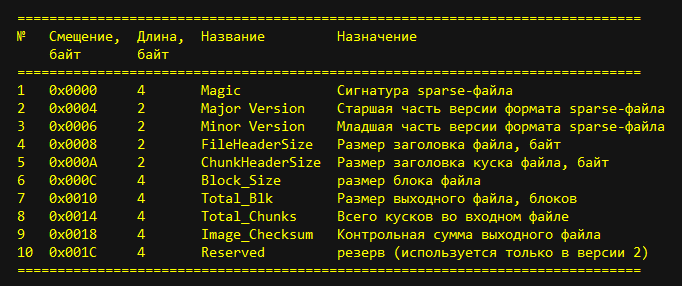
Fig. 2. Header of the sparse file
Briefly consider all the header fields.
The Magic field , 4 bytes long, contains the signature (number 0xed26ff3a) and is used to identify the sparse file as a file type.
The Major Version and Minor Version fields, each 2 bytes long, contain the version number of the sparse file format . Now it is version 1.0.
Field FileHeaderSize 2 bytes long, contains the size of the sparse headerfile in bytes. Currently, there are two versions of the header, differing only in its size: 0x1C (28) bytes and 0x20 (32) bytes. Accordingly, this field also contains the number or 0x1C, or 0x20.
The 2-byte ChunkHeaderSize field contains the size of the header for pieces of a sparse file. Regardless of the type of pieces, it contains the number 0x0C (12).
The Block_Size field , 4 bytes long, contains the block size of the sparse file. To compress FS images of the ext2-ext4 type into a sparse file, the value of this field is 0x1000 (4096).
The Total_Blk field , 4 bytes long, contains the size of the source file (img) in blocks. Total_Chunks
field4 bytes long, contains the number of parts into which the source (input) file was divided. The same number of pieces are contained in the output file ( sparse ).
The Image_Checksum field contains the checksum of the output file data (sparse) calculated by the Crc32 algorithm for the entire file (header + data).
Structure of the data area of sparse file pieces
Following the header is a data area consisting of a list of pieces of a sparse file.
Each piece has a piece header and piece data.
The header has a length of 0x0C (12) bytes, as indicated in the ChunkHeaderSize field of the sparse- file header and contains the following fields:

Fig. 3. Chunk Header Structure
The Chunk_Type field , 2 bytes long, contains the identifier of the chunk and can take the following values:
- 0xCAC1 - a piece of type Raw , designed to store non-repeating data. The chunk size is equal to the amount of data in bytes + the size of the chunk header;
- 0xCAC2 - a piece of type Fill describes the repeated part of the input data, contains zero or repeated data in encoded form. The chunk size is equal to the size of the header + 4 bytes per placeholder;
- 0xCAC3 - a piece of type DontCare contains no data at all. The size of the chunk is the size of the header of the chunk, i.e. 12 bytes;
- 0xCAC4 - a piece of type Crc contains the checksum of the file, calculated according to the Crc32 algorithm. The size of the chunk is the size of the header + 4 bytes per checksum value.
The Reserved field , 2 bytes long, is not used and is always zero.
The 4-byte Chunk_Size field contains the size of the source chunk in the input file (img), expressed in blocks.
The Total_Size field , 4 bytes long, contains the size of the received piece in the output sparse file, expressed in bytes. The calculation takes into account both the length of the header and the length of the piece data.
Following the header are data that varies depending on the type of piece.
Because piece type Raw intended for non-recurring data storage, the data pieces fully coincide with the data of its corresponding portion of the input file. It has the largest size since the amount of data can reach the value of the selectedborders .
A piece of type Fill as data contains only one four-byte number (4-byte placeholder), repeated in the corresponding part of the input file. It replaces the entire area occupied by these duplicate data without listing them, which leads to their compression.
A piece of type Crc as a data contains a checksum of a piece calculated according to the Crc32 algorithm for all the data of the piece .
An exception is a piece of type DontCare , which does not contain data at all, but the Chunk_Size field is still populated. It is a pointer (offset) to the beginning of the next piece of data in the input file.
3.1.2 Sparse File Algorithms
When working with a sparse-file operation is performed coding "wet» ( Raw ) img-file in the sparse -file and decoding of sparse -file in the source file.
The encoding of the input Raw image of the sparse format section is performed according to the following algorithm:
- The input image of the section is viewed block by block and the type of each block is determined.
- Running blocks of the same type are grouped together. The current group ends if a block type change occurs and a new one begins.
Contract running Fill blocks are combined into Fill groups. This takes into account the repeating value, which within the same group should be the same. If the next coming Fill block has a different repeating value, a new Fill group is created.
Contracts going Raw blocks are combined into Raw groups. - All received groups are converted into chunks of the sparse format file . In this case, the Raw group containing the non-repeating data is copied completely, without changes, to the data area of the Raw piece . And the whole Fill- group is replaced with one piece of the Fill type , containing one repeating element in the data area of this piece.
- The header of the sparse file is populated.
Decoding a sparse file to the original image is performed according to the following algorithm:
- A new empty file is created, the size of which in blocks is taken from the Total_Blk field of the sparse- file header .
- Each piece of the list from the data area of the sparse file is decoded sequentially , filling the output file sequentially, starting at address 0x0000. In this case, the title is read for the piece, and then:
- Raw chunk data is completely copied from the input file to the output.
In this case, the read pointer of the input file and the write pointer of the output file are moved by the number of bytes copied. - For a piece of type Fill , the filler element is copied to Total_Size divided by 4 times.
In this case, the read pointer of the input file moves to 4 bytes of placeholder. The output file write pointer moves to the number of bytes occupied by the placeholders. - For chunks of type DontCare, the read pointer of the input file does not move, and in the output file, the write pointer moves to the number of byte blocks specified in the Chunk_Size field of the chunk.
- Raw chunk data is completely copied from the input file to the output.
3.1.3 Examples of working with sparse files
When working with sparse files, two questions most often arise:
- How to restore the original image from a sparse file?
- How to convert the source image to a sparse file?
Consider them according to admission ...
How to restore the original image from a sparse file?
For example, consider the process of restoring an oem partition image from a sparse file of Lenovo Moto Z MU [4]. All actions are performed using a hex editor, for example, WinHex.
The oem.img source file containing a compressed oem partition image is 69MB in size. Let's see its title:

Fig. 4. Header Moto Z
From the address 0x0000 there is a file signature indicating that the file is of the sparse file type and consists of pieces. The signature is marked in blue.
Next, the fields containing the version of the sparse-file (1.0) are highlighted in green.
Then the fields FileHeaderSize and ChunkHeaderSize are highlighted in redcontaining the size of the file header (0x001C) and the size of the piece header (0x000C), respectively.
At offset 0x000C, the Block_Size field is located , indicating the block size of the sparse file. The block size value is 0x00001000.
At offset 0x0010, the Total_Blk field is located , containing the size of the source file in blocks. It is highlighted in yellow and has a value of 0x0000С021.
At offset 0x0014, the Total_Chunks field is located , containing the number of pieces contained in the sparse file. It is highlighted in purple and has a value of 0x0000001F.
At offset 0x0018, the Image_Checksum field is locatedcontaining the checksum of the sparse file. This field contains 0, which means that the CS was not calculated and is not taken into account when loading this file into the memory of the MU.
Starting with the address 0x001C, the header of the first piece of the sparse file is located:

Fig. 5. Chunk Title CAC1
It can be seen that the Chunk_Type field contains the 0xCAC1 value highlighted in blue. The next 2 bytes are empty, and then the Chunk_Size field is marked in red, containing the number of blocks of the input file (0x00000001) encoded in a piece.
Next is the Total_Size fieldcontaining the length of the piece along with the header, expressed in bytes (0x0000100C). It is highlighted in green. We always need a size without a header, so the length of only the data is: 0x100C - 0x000C = 0x1000.
Immediately after the header, starting at address 0x0028, there is an array of piece data.
So, to restore the original image, perform the following steps:
- open the source sparse file oem.img in a hex editor;
- select the field values from the file header, create a new empty file of size
and save it under the name, for example, oem_ext4.img;Total_Blk * Block_Size = 0x000C021 * 0x1000 = 0х0C021000 байт (192)МБ - go to the processing of the first piece;
- its type is CAC1, so copy the data array (starting at offset 0x0028 with size 0x1000) and paste it into the generated output file;
- move on to the next piece. Its type is CAC2, respectively, the placeholder is 0xFFFFFFFF, and the number of placeholders is 0x1D blocks:

Fig. 6. The second piece of CAC2
Insert the placeholders in the created file in the amount of0x001D * 0x1000 = 0x01D000 или 118784 байта - Etc. we will perform the described steps to decode the pieces to the end of the source file.
The result is a file containing a file system of type ext4, size 192MB.
How to convert the source image to a sparse file?
For simplicity, we’ll take the oem_ext4.img image we just received and try to turn it into a sparse file. In this case, it is necessary to create a new file of size 0x001C (28) bytes, place the header of the sparse file in it, and then sequentially view the source file, dividing it into pieces and encoding them, place in the new file all the created sparse bites. And of course, save the new file under the name, for example, oem_sparse.img .
To fill in the file header, enter the signature of the sparse file in the first 4 bytes :

Fig. 7. Header of the sparse file
Next, sequentially write the values:
- номера версии sparse-файла ( занимает 4 байта):

рис.8 Номер версии sparse-файла - размер заголовка sparse-файла (2 байта):

рис.9 Размер заголовка sparse-файла - размер заголовка куска (2 байта):

рис.10 Размер заголовка куска - размер блока в байтах (4 байта):

рис.11 Размер блока
We leave the remaining fields free, because their values will appear with us only after the final creation of the output file.
Let's now look at how to code, i.e. create, different types of pieces.
Any type of piece has a title. Therefore, we will create it first of all: create a file with a size of 12 bytes in the hex editor:

Fig . 12 Blank title for a piece.
Next, we will examine how and what to fill in pieces.
A piece of type Raw
In the first 2 bytes of the header, write its type (CAC1):

Fig . 13 Type of the piece CAC1
Then insert the data size (0x00000001) expressed in blocks in the field:

Fig . 14 Size in blocks
Well, finally, the size of the piece in bytes (0x0000100C), i.e. header length + data length:

Fig. 15 Piece size САС1
After the header, insert the data, i.e. 0x1000 (4096) bytes from the source file:

Fig . 16 Chunk data САС1
Let us proceed to the creation of the next chunk.
A piece of type Fill
In the first 2 bytes of the header, write its type (CAC2):

Fig . 17 Chunk type CAC2
Insert the size of the piece data (0x001D), expressed in blocks:

Fig. 18 Size in CAC2 blocks
Insert the size of the piece in bytes (0x0010), t .e. header length + data length:

Fig.19 piece size CaC2
Adding a piece of data. For CAC2, this is a placeholder (0xFFFFFFFF):

Fig . 20 Data of a piece of САС2
Let's move on to creating the next piece.
Кусок типа DontCare
В первые 2 байта заголовка запишем его тип (CAC3):

рис.21 Тип куска CAC3
Вставляем значение смещения до следующего куска (0ххххх), выраженное в блоках, по адресу 0х0004 заголовка.
Вставляем размер куска в байтах (0х000С), т.е. просто длина заголовка, т.к. кусок этого типа данных не имеет, по адресу 0х0008 заголовка:

рис.22 Размер куска САС3
Перейдем к созданию следующего куска.
Кусок типа Crc
В первые 2 байта заголовка запишем его тип (CAC4):

рис.23 Тип куска CAC4
Вставляем размер данных куска (0х001D), выраженное в блоках:

рис.24 Размер в блоках САС4
Insert the size of the piece in bytes (0x0010), i.e. header length + data length:

fig.25 piece size SAS4
Adding a piece of data. For CAC4, this is the checksum of the piece calculated according to the CRC32 algorithm:

Fig . 26 Data of the CAC4 piece We
have already sorted everything by bones: we create the header of the sparse piece; and immediately after it we add the data he needs
Now the process of encoding the source file into a sparse file is as follows:
- create an output file of 0x001C bytes in the hex editor and fill in the header fields of the sparse file in it as described above;
- open the source file in a hex editor;
- look through 4096 bytes (one block) and determine the type of piece.
- create a piece of type САС1 in the output file;
- просматриваем следующие 4096 байт (один блок) и определяем тип куска.
- создаем в выходном файле кусок типа САС2;
- выполняем поблочный просмотр исходного файла до конца. Все блоки кодируем в куски и складываем их в выходном файле.
- просматриваем выходной файл и объединяем куски одного типа, расположенные последовательно, в одну группу, а куски другого типа — в другую группу. В группе остается один заголовок от первого куска, в котором корректируются значения двух полей:
- Chunk_Size — общий размер группы исходных кусков входного файле (img), выраженный в блоках;
- Total_Size — размер полученной группы в выходном sparse-файле, выраженный в байтах.
- appends a field Total_Blk header source file size in blocks, as in the Total_Chunks file number of pieces of header;
To be continued...
3.2._sparsechunk files
4.creation of dat files
5. Sources of information
1. "Sparse_file" .
2. "s90-a_row_s125_141114_pc_qpst - firmware . "
3. system / core / libsparse / sparse_format.h
4. “Firmware for Lenovo Moto Z device” .
5. Victara_Retail_China_XT1085_5.1_LPE23.32-53_CFC.xml.zip - firmware for the Lenovo Moto X device.