September 19, 2017 at 11:20
Prototyping in Python-Arduino
- Tutorial
Hello, Habr! I want to tell by examples about the simplest way to create something complex. The essence of the terrible word "prototyping" comes down to the use of analogies or patterns in the Arduino project.
I don’t want to frighten the beginners of Python-Arduino users with long words, so we’ll follow the examples right away.
Zoomer [1]. emits sound when equipped with a digital HIGH value (that is, +5 V), which can be provided using the Arduino digital pins [2].
However, instead of performing simple digital output, as was done with the motion sensor, we implement Python programming tricks to generate various sound patterns and create various sound effects.
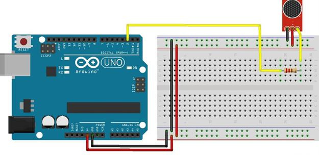
To complete these steps, we are going to implement a special Python function that will take the pin number, repetition time, and sample number as input.
Before proceeding to explain the code, you must open the program file, buzzerPattern.py, from the code folder. At the beginning of the code, you can find the Python function buzzerPattern (), which will be called from the main program with the appropriate parameters. This function is the core of the entire program.
The function contains two arrays of hard-code arrays, pattern1 and pattern2. Each of them contains the on and off time of the buzzer for a second, which is the working cycle of the template.
For example, in pattern1, 0.8 represents the time during which the buzzer should be turned on, and 0.2 represents the opposite.
The function will repeat this buzzer pattern for the repetition periods specified by the function argument. After starting the for loop with a repeat value, the function checks the pattern number from the function argument and executes the pattern.
Once the entire repetition cycle is completed, again completely disable the buzzer, if it is enabled, and safely disable the board using the exit () method:
The rest of the program is relatively simple because it contains code for importing libraries and initializing the Arduino board. Once the board is initialized, execute the function buzzerPattern () with the input argument (2, 10, 1). This argument will ask the function to play pattern1 10 times on pin number 2:
DC [3] is widely used in robotic applications. They are available in a wide range of voltage characteristics, depending on the application.
In this example, we use a 5V DC motor because we want to supply power using the Arduino board itself. Since the Arduino digital output can have only two states, that is, HIGH (+ 5V) or LOW (0V), it is not possible to control the motor speed using only OUTPUT mode.
As a solution, we are going to implement PWM mode using digital pins that are capable of supporting PWM. When using pyFirmata, pins configured in PWM mode accept any floating-point input values from 0 to 1.0, which represent 0 and 5 V., respectively.
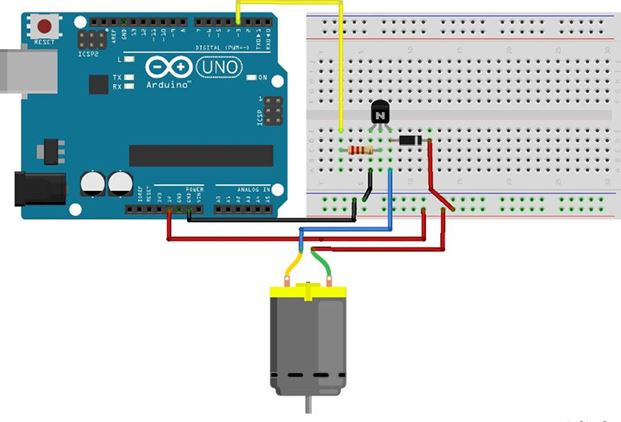
In order not to damage the Arduino board due to a large random current loss, we will use a transistor as a switch, which uses only a small amount of current to control the large current in the DC motor.
To complete the circuit connection, as shown in the following diagram, you need an NPN transistor (TIP120, N2222 or similar), one diode (1N4001 or similar) and a 220 ohm resistor with a DC motor.
Connect the base of the transistor to digital pin 3, which also supports PWM mode. Connect the remaining components as shown in the diagram:
The user- defined function, dcMotorControl () , takes the speed and duration of the engine as input parameters, as described in the following code fragment:
We use the same code to import the necessary library and initialize the Arduino board.
After initialization, we assign the digital output mode 3 as PWM, as can be seen from the use of the get_pin ('d: 3: p') method. This code reflects the indirect pin mode assignment mode, which we learned about in the previous section:
In the process of collecting manual data from the user, we run a combination of the try / except operator (to free the board on exit) and the while statement (to receive continuous data from the user).
The code template introduces the input () method to retrieve custom values (engine speed and engine start time) from the Python interactive terminal. Once these values are received from the user, the program calls the dcMotorControl () function to perform a motor action: try:
try:
In the previous template, we controlled the speed of the DC motor using PWM. Similarly, you can control the brightness of the LED. Instead of asking the user to enter brightness, we will use the Python module randomly in this template.
We will use this module to generate a random number from 1 to 100, which will later be used to write this value to the output and randomly change the brightness of the LED.
This randint () function is a really useful function provided by a random module, and it is widely used when testing prototypes by quickly sending random signals.
You will need a pull-up resistor to connect the LED to the Arduino pin. It is necessary to connect the anode of the LED (longer knife) to the digital output 11 through one resistor with a resistance of 220 Ohms and connect the cathode (shorter leg) to ground:
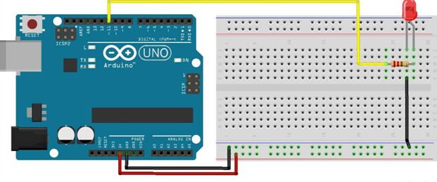
It is important to note that digital pin 11 on the Arduino Uno is also capable of PWM along with digital with pins 3, 5, 6, 9 and 10.
We use a Python code called ledBrightnessPWM.py The float value between 0 and 1.0 is randomly selected before passing it to the PWM output.
The first few lines of code import the necessary libraries and initialize the board.
In this example, we use the direct pin assignment method. In the following code snippet, digital pin 11 is assigned to PWM mode:
After the end of the cycle, you must safely disconnect the Arduino board after turning off the LED for the last time.
In this publication, using simple examples, the most common approach to programming sensors, control devices to them is described. Python codes are presented that can be easily used in Arduino's own projects. For illustrative purposes, various sensors and code templates were used.
I don’t want to frighten the beginners of Python-Arduino users with long words, so we’ll follow the examples right away.
Buzzer - Generates an audible alarm.
Zoomer [1]. emits sound when equipped with a digital HIGH value (that is, +5 V), which can be provided using the Arduino digital pins [2].
However, instead of performing simple digital output, as was done with the motion sensor, we implement Python programming tricks to generate various sound patterns and create various sound effects.
Connections
Python code
To complete these steps, we are going to implement a special Python function that will take the pin number, repetition time, and sample number as input.
Before proceeding to explain the code, you must open the program file, buzzerPattern.py, from the code folder. At the beginning of the code, you can find the Python function buzzerPattern (), which will be called from the main program with the appropriate parameters. This function is the core of the entire program.
The function contains two arrays of hard-code arrays, pattern1 and pattern2. Each of them contains the on and off time of the buzzer for a second, which is the working cycle of the template.
For example, in pattern1, 0.8 represents the time during which the buzzer should be turned on, and 0.2 represents the opposite.
The function will repeat this buzzer pattern for the repetition periods specified by the function argument. After starting the for loop with a repeat value, the function checks the pattern number from the function argument and executes the pattern.
Once the entire repetition cycle is completed, again completely disable the buzzer, if it is enabled, and safely disable the board using the exit () method:
def buzzerPattern(pin, recurrence, pattern):
  pattern1 = [0.8, 0.2]
  pattern2 = [0.2, 0.8]
flag = True
  for i in range(recurrence):
    if pattern == 1:
      p = pattern1
    elif pattern == 2:
      p = pattern2
    else:
      print "Please enter valid pattern. 1 or 2."
      exit
    for delay in p:
      if flag is True:
        board.digital[pin].write(1)
        flag = False
        sleep(delay)
      else:
        board.digital[pin].write(0)
        flag = True
        sleep(delay)
  board.digital[pin].write(0)
board.exit()
The rest of the program is relatively simple because it contains code for importing libraries and initializing the Arduino board. Once the board is initialized, execute the function buzzerPattern () with the input argument (2, 10, 1). This argument will ask the function to play pattern1 10 times on pin number 2:
from pyfirmata import Arduino
from time import sleep
port = '/dev/cu.usbmodemfa1331'
board = Arduino(port)
sleep(5)
buzzerPattern(2, 10, 1)
DC Motor - Motor Speed Control Using PWM Motors
DC [3] is widely used in robotic applications. They are available in a wide range of voltage characteristics, depending on the application.
In this example, we use a 5V DC motor because we want to supply power using the Arduino board itself. Since the Arduino digital output can have only two states, that is, HIGH (+ 5V) or LOW (0V), it is not possible to control the motor speed using only OUTPUT mode.
As a solution, we are going to implement PWM mode using digital pins that are capable of supporting PWM. When using pyFirmata, pins configured in PWM mode accept any floating-point input values from 0 to 1.0, which represent 0 and 5 V., respectively.
Connections
In order not to damage the Arduino board due to a large random current loss, we will use a transistor as a switch, which uses only a small amount of current to control the large current in the DC motor.
To complete the circuit connection, as shown in the following diagram, you need an NPN transistor (TIP120, N2222 or similar), one diode (1N4001 or similar) and a 220 ohm resistor with a DC motor.
Connect the base of the transistor to digital pin 3, which also supports PWM mode. Connect the remaining components as shown in the diagram:
Python code
The user- defined function, dcMotorControl () , takes the speed and duration of the engine as input parameters, as described in the following code fragment:
def dcMotorControl(r, deltaT):
pwmPin.write(r/100.00)
sleep(deltaT)
  pwmPin.write(0)
We use the same code to import the necessary library and initialize the Arduino board.
After initialization, we assign the digital output mode 3 as PWM, as can be seen from the use of the get_pin ('d: 3: p') method. This code reflects the indirect pin mode assignment mode, which we learned about in the previous section:
# Set mode of pin 3 as PWM
pwmPin = board.get_pin('d:3:p')
In the process of collecting manual data from the user, we run a combination of the try / except operator (to free the board on exit) and the while statement (to receive continuous data from the user).
The code template introduces the input () method to retrieve custom values (engine speed and engine start time) from the Python interactive terminal. Once these values are received from the user, the program calls the dcMotorControl () function to perform a motor action: try:
try:
 while True:
    r = input("Enter value to set motor speed: ")
    if (r > 100) or (r <= 0):
      print "Enter appropriate value."
      board.exit()
      break
t = input("How long? (seconds)")
    dcMotorControl(r, t)
except KeyboardInterrupt:
board.exit()
  os._exit
LED - controlling the brightness of the LED using PWM
In the previous template, we controlled the speed of the DC motor using PWM. Similarly, you can control the brightness of the LED. Instead of asking the user to enter brightness, we will use the Python module randomly in this template.
We will use this module to generate a random number from 1 to 100, which will later be used to write this value to the output and randomly change the brightness of the LED.
This randint () function is a really useful function provided by a random module, and it is widely used when testing prototypes by quickly sending random signals.
Connections
You will need a pull-up resistor to connect the LED to the Arduino pin. It is necessary to connect the anode of the LED (longer knife) to the digital output 11 through one resistor with a resistance of 220 Ohms and connect the cathode (shorter leg) to ground:
It is important to note that digital pin 11 on the Arduino Uno is also capable of PWM along with digital with pins 3, 5, 6, 9 and 10.
Python code
We use a Python code called ledBrightnessPWM.py The float value between 0 and 1.0 is randomly selected before passing it to the PWM output.
The first few lines of code import the necessary libraries and initialize the board.
from pyfirmata import Arduino, INPUT, PWM
from time import sleep
import random
port = '/dev/cu.usbmodemfa1311'
board = Arduino(port)
sleep(5)
In this example, we use the direct pin assignment method. In the following code snippet, digital pin 11 is assigned to PWM mode:
pin = 11
Board.digital [pin] .mode = PW
After the end of the cycle, you must safely disconnect the Arduino board after turning off the LED for the last time.
board.digital[pin] .write(0)
board.exit()
conclusions
In this publication, using simple examples, the most common approach to programming sensors, control devices to them is described. Python codes are presented that can be easily used in Arduino's own projects. For illustrative purposes, various sensors and code templates were used.