Night light with scheduled shutdown
With the birth of a child there was a question about a nightlight. Somewhere read that it is necessary for a restful sleep. Quickly accustomed to sleep with a dim light. It is very convenient to wake up from screams and howls in the middle of the night and see what the baby is complaining about (if you can understand). Also in dim light, you can soothe, turn over and continue to sleep.
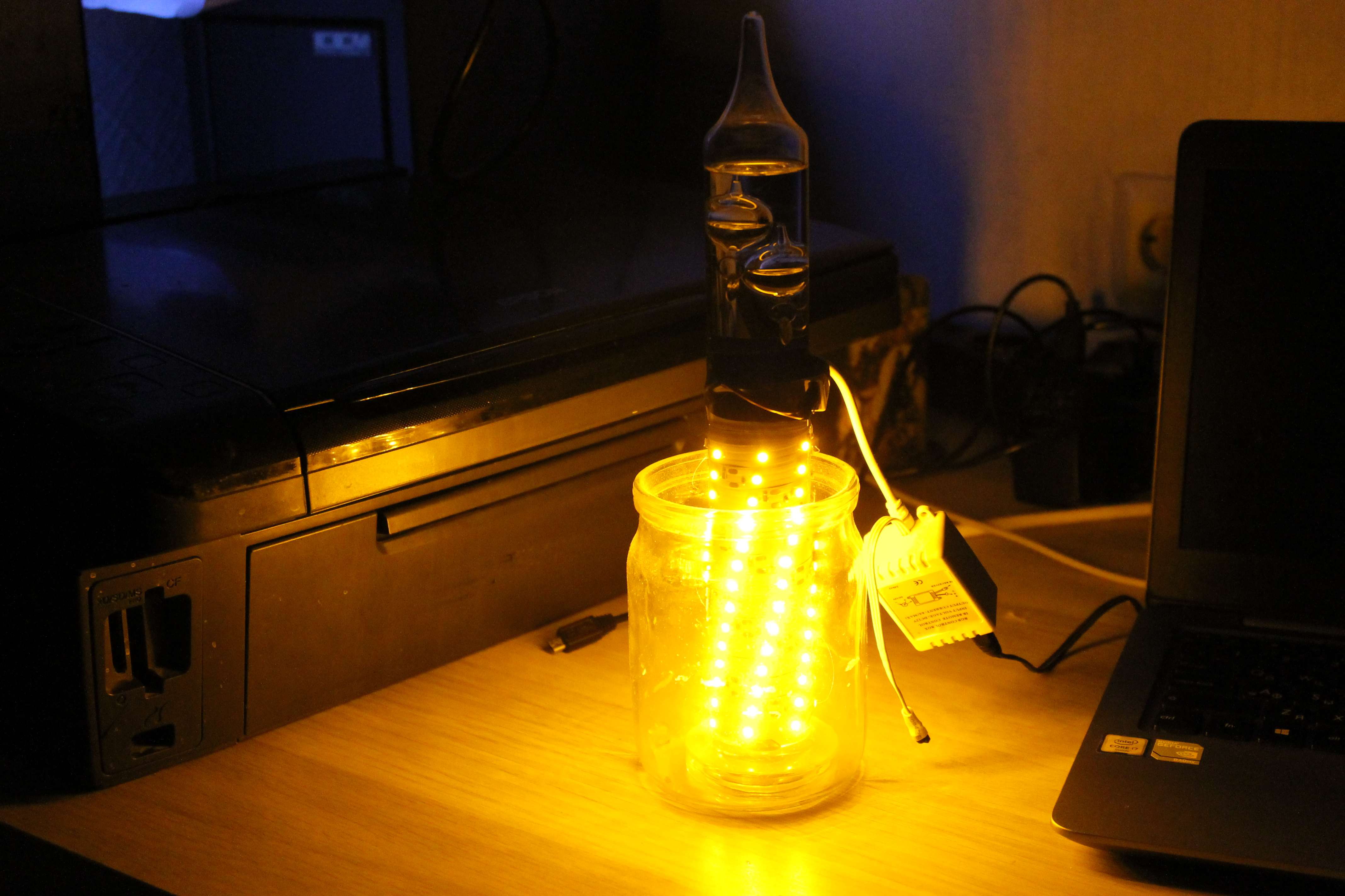
First, a test sample of the lamp was made from a piece of yellow LED strip (12 volts), which was used for 1.5 years.
In addition to the fragility of the design, it became annoying every morning to remove the power supply unit from the outlet. I get up in the morning, from the street in the room comes enough light. Thus, the lamp is wasted for several hours every day. Once again in half a year, the Chinese controller of the RGB tape forgot the current setting and it was necessary to search for the control panel to remind it how to work. I decided to make a new lamp with automatic shutdown, with color adjustment using potentiometers as well as radio.
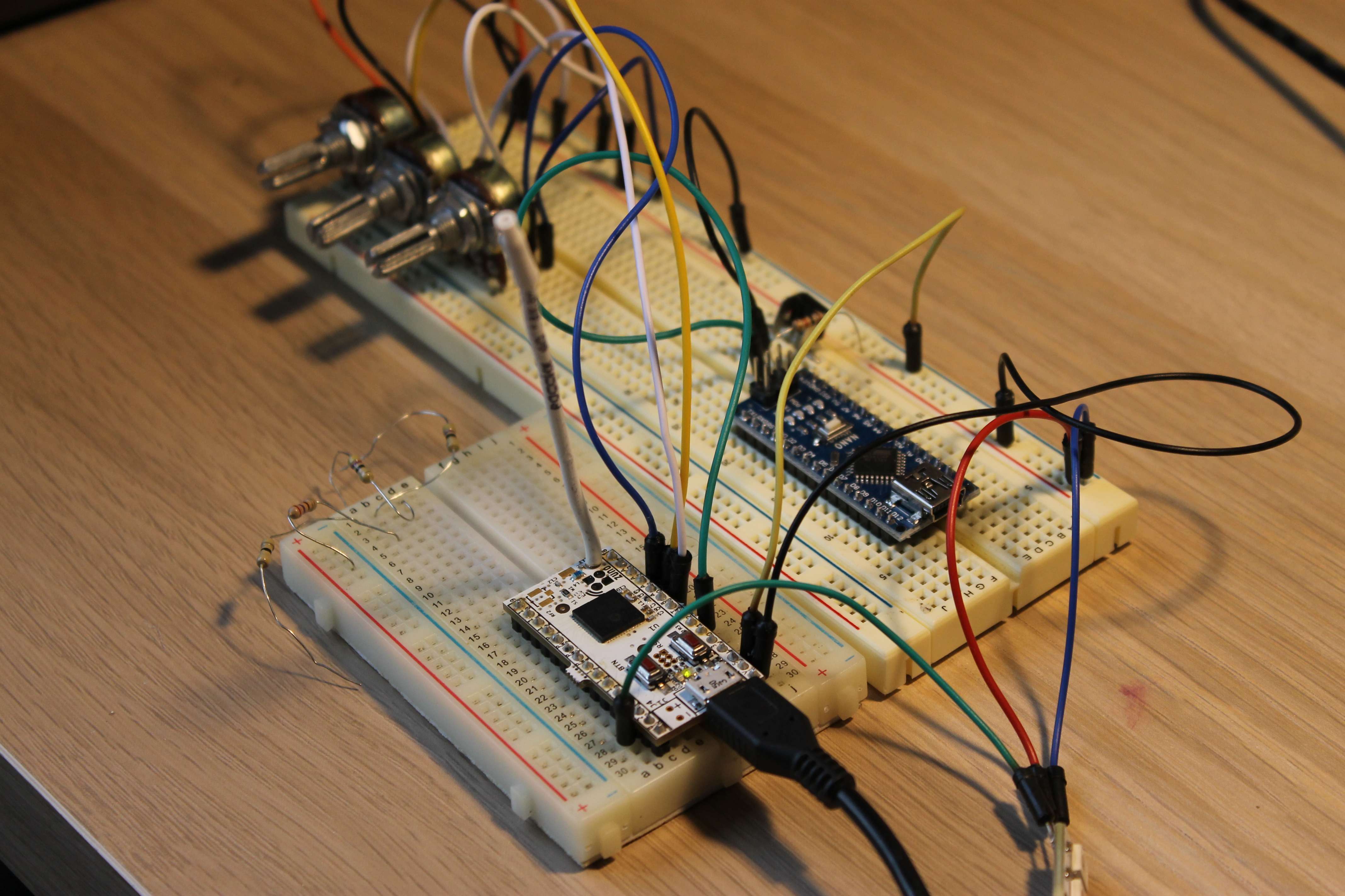
Quickly assembled a prototype based on arduino nano. Debugged basic functionality.
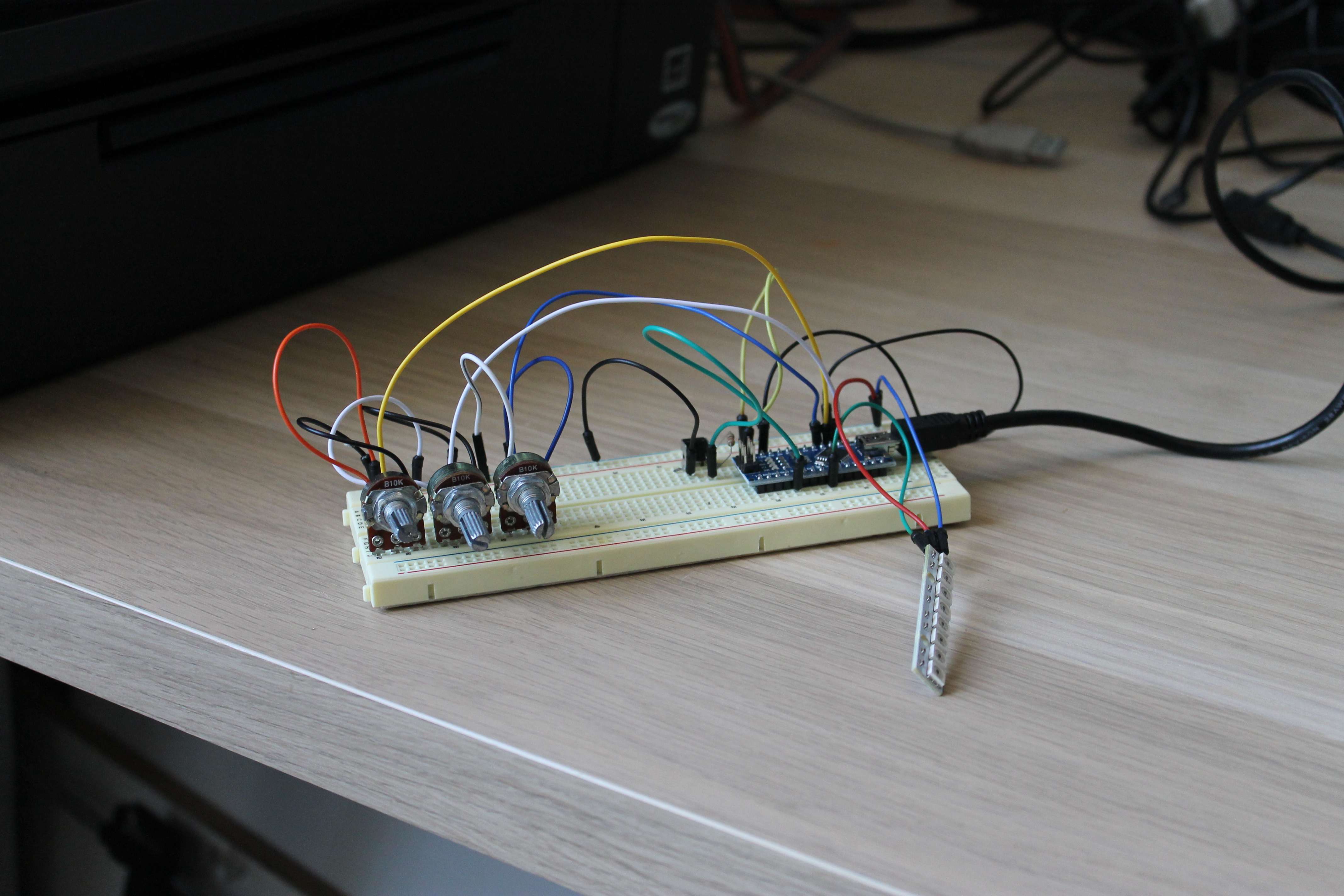
Taking this opportunity I tried Fritzing. It was not pleasant, but pictures turn out evident and "cheerful". Apparently nothing new has been invented.

Replaced “nano” with a little-known, arduino-compatible module with a built-in radio transceiver (8-bit controller, performance and hardware versus “nano”). At home, I already have one device operating at a frequency of 868 MHz, this will be the second. Brief characteristics from the manufacturer's website:
Brief characteristics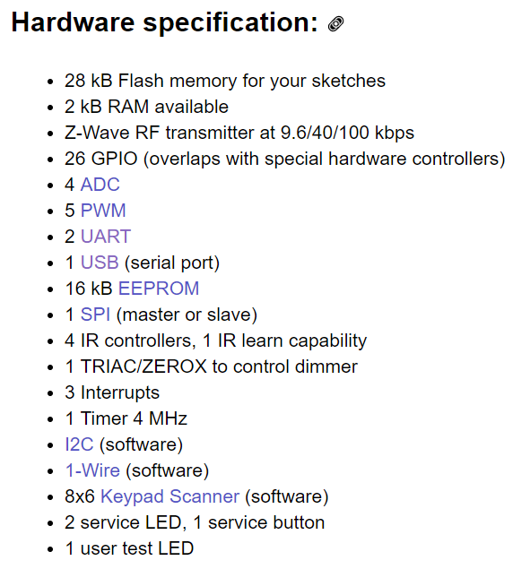
I do not see big problems to do the same on ESP8266 (there is a convenient online firmware builder for scripts on LUA). A little harder on Bluetooth (for flashing the HM-10 module you need an inexpensive programmer, an environment for developing and understanding the protocol). Although you can use the Bluetooth module with arduine. But I used ZUNo, because it’s been waiting for me for a long time, and the entire infrastructure for connecting and managing similar devices to one network is ready (I’m talking about the network controller of a smart home).
For all used legs on the Arduino there were analogues in the module.
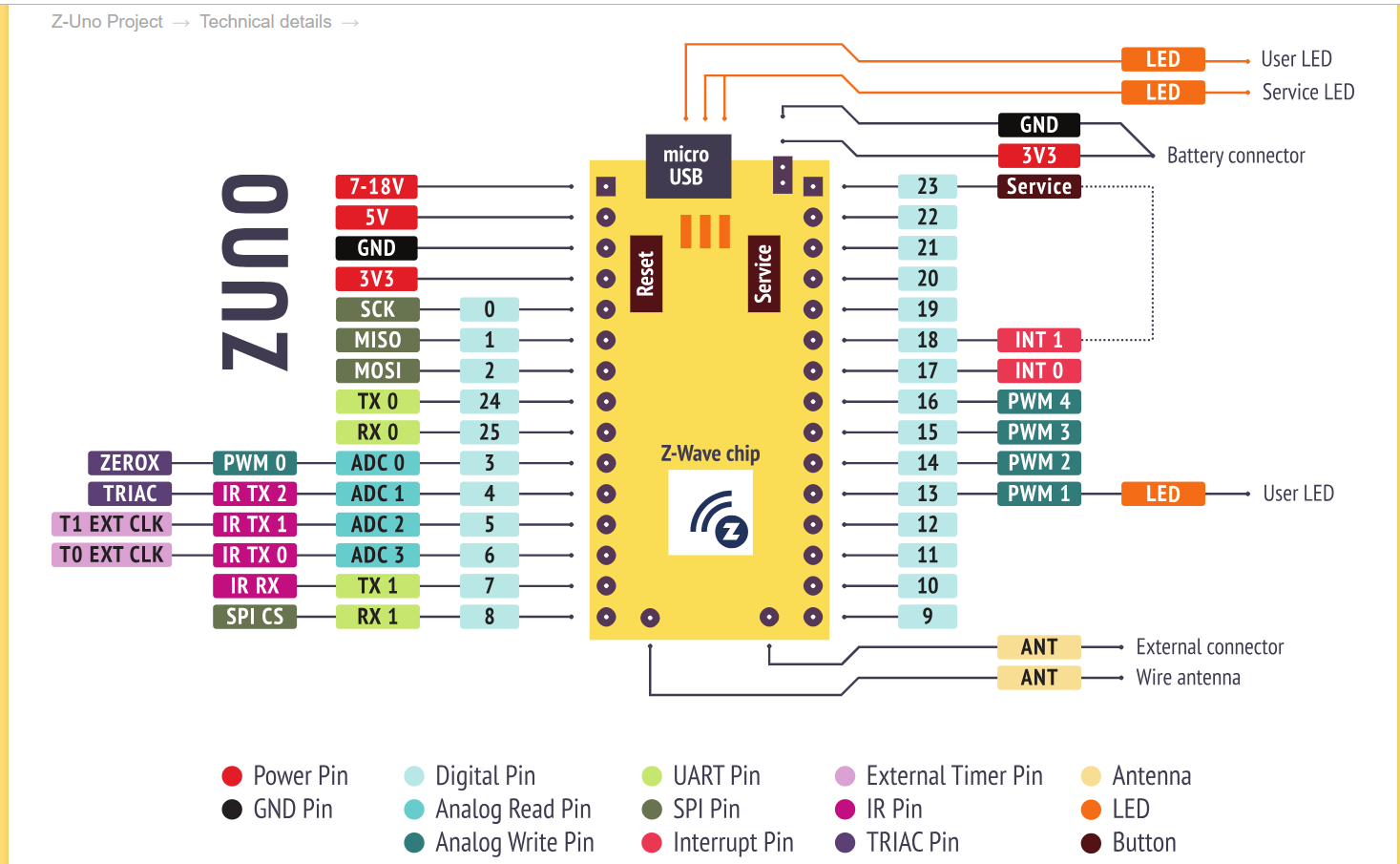
To work with the module from the Arduino IDE you need to configure it (a description of the settings is on the manufacturer's website). The miracle did not happen. When trying to compile, I received the error “doesn't support“ for ”statement with empty columns or without body!”. I used the Adafruit_NeoPixel library. I climbed into it and saw how many cycles it had and closed it. I had to go back to the manufacturer's site and look for examples of working with LEDs (the example was quickly found). So, I'm not the first who faced a similar problem.
In order for this lamp to be controlled by radio in the Arduino code, you need to add a macro and implement several functions:
ZUNO_SETUP_CHANNELS(
      ZUNO_SWITCH_MULTILEVEL(getRed, setRed),
      ZUNO_SWITCH_MULTILEVEL(getGreen, setGreen),
      ZUNO_SWITCH_MULTILEVEL(getBlue, setBlue),
      ZUNO_SWITCH_BINARY(switch_getter, switch_setter)
);
This macro describes a Z-Wave device with three multi-level switches (RGB control) and one simple switch (simple on / off).
I have the simplest implementation of functions (as in the examples on the manufacturer’s website). You can see in the attached listing.
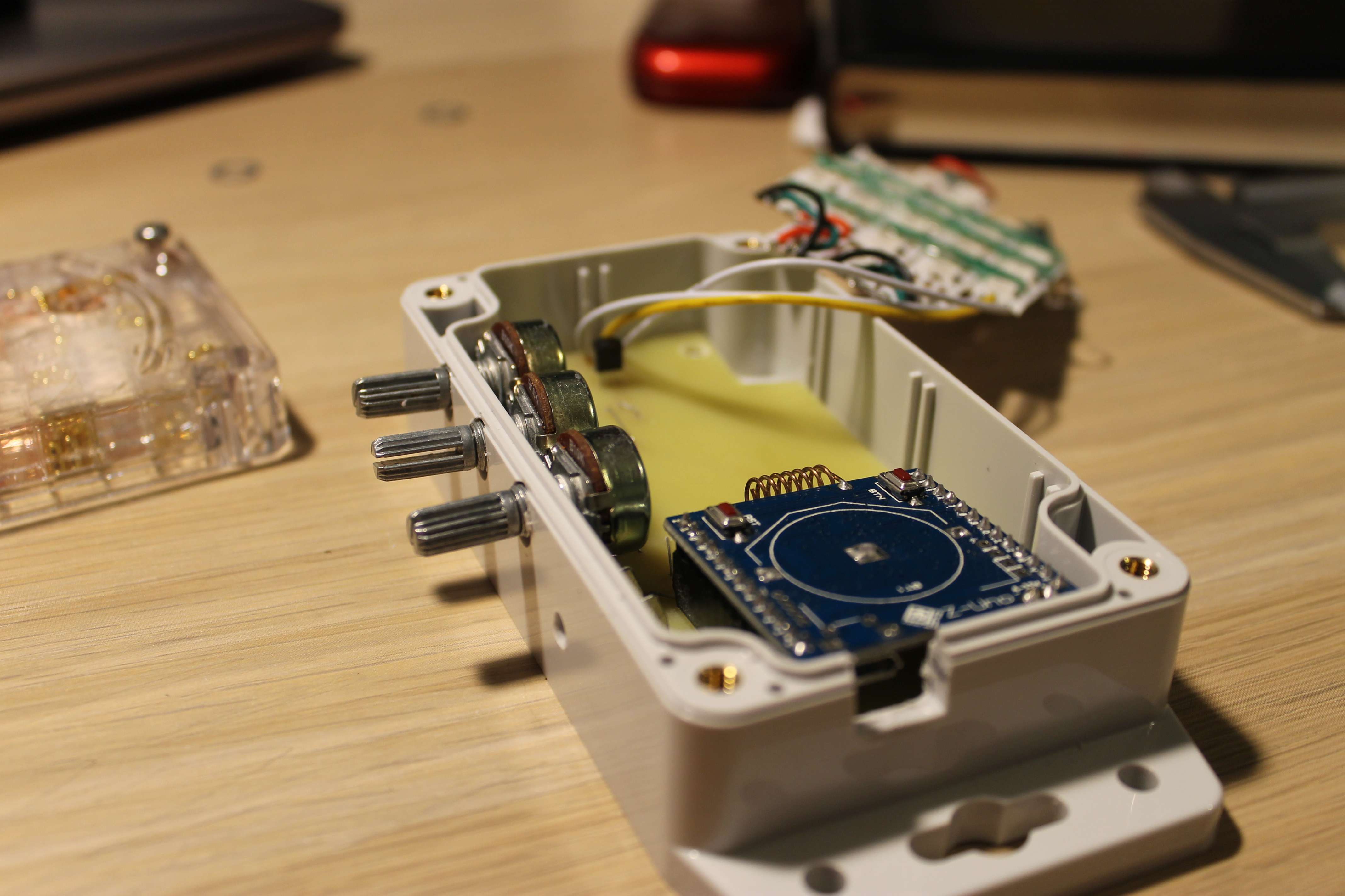
Case selection
I already had a case. Sealed with a transparent cover . Under the cover fit 25 LEDs. The tests were successful. The lamp has a large margin in brightness for my room. The cover of this case is transparent, so I decided to dissipate the light a little.
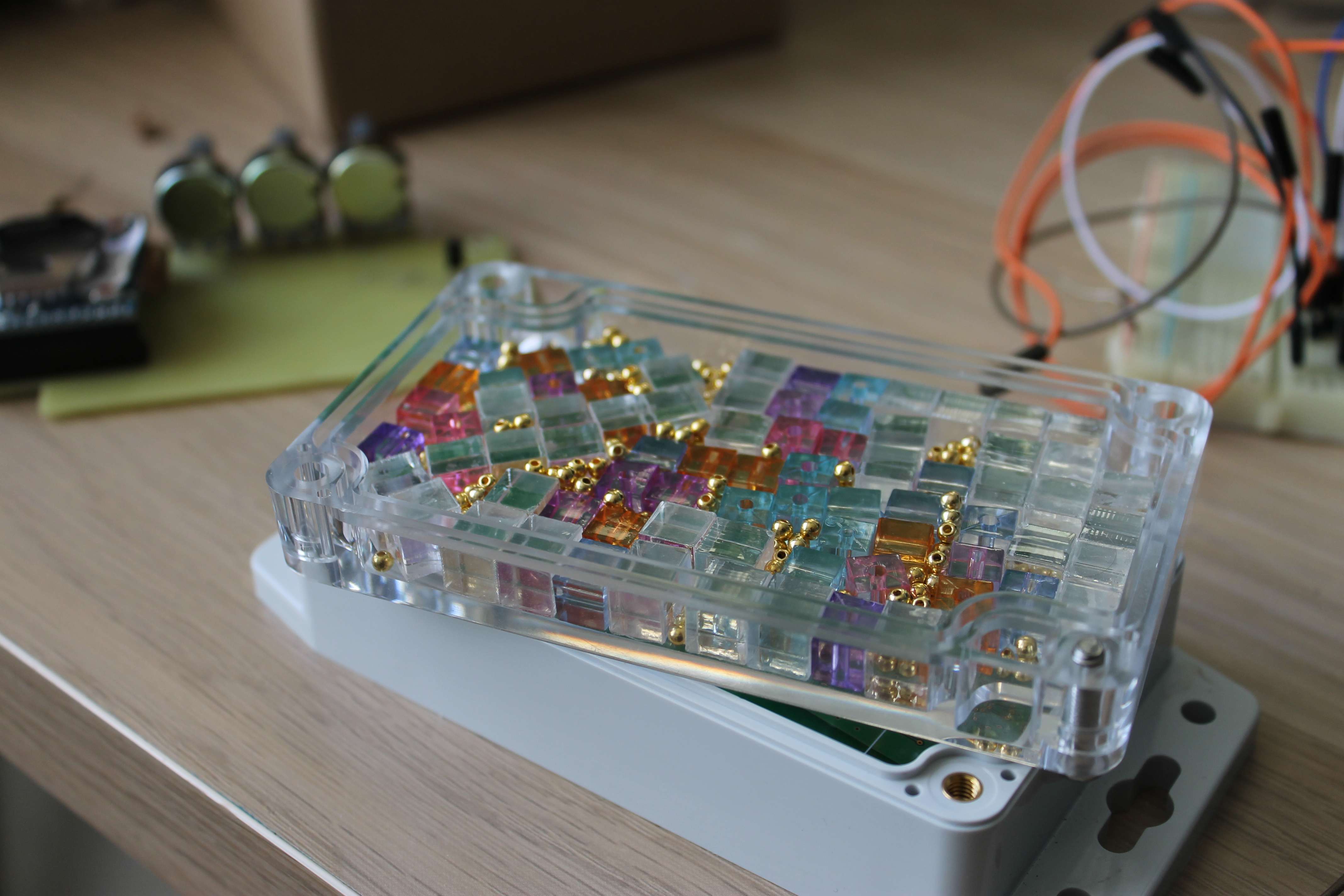
Sketched colored beads and acrylic cubes, filled with transparent epoxy. Paint from the colored beads under the influence of resin dissolved.

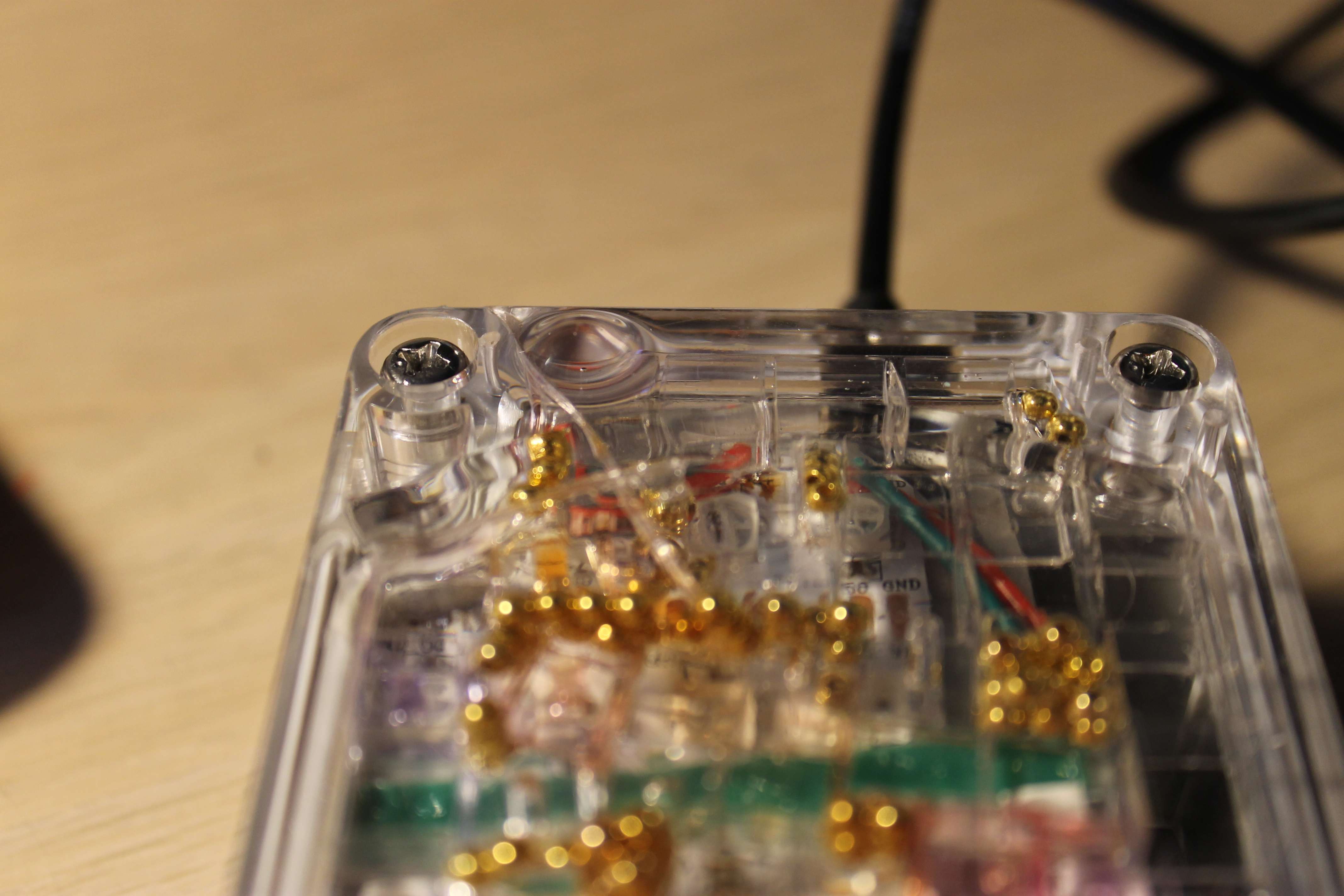
The most interesting thing is that the cover from the hermetic case leaked and almost all of the resin leaked. I do not know where I managed to hit the lid, but after drying the crack is clearly visible.
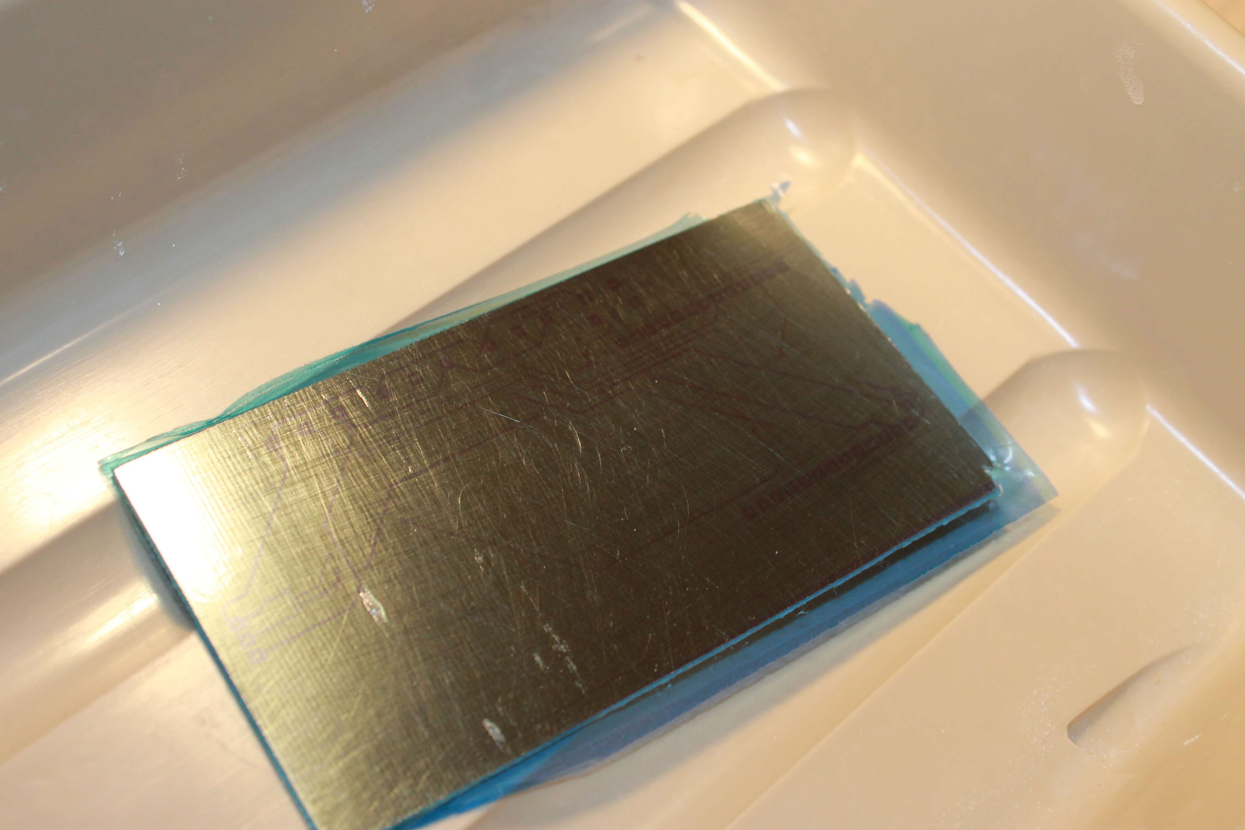
Printed circuit board made photoresistive.
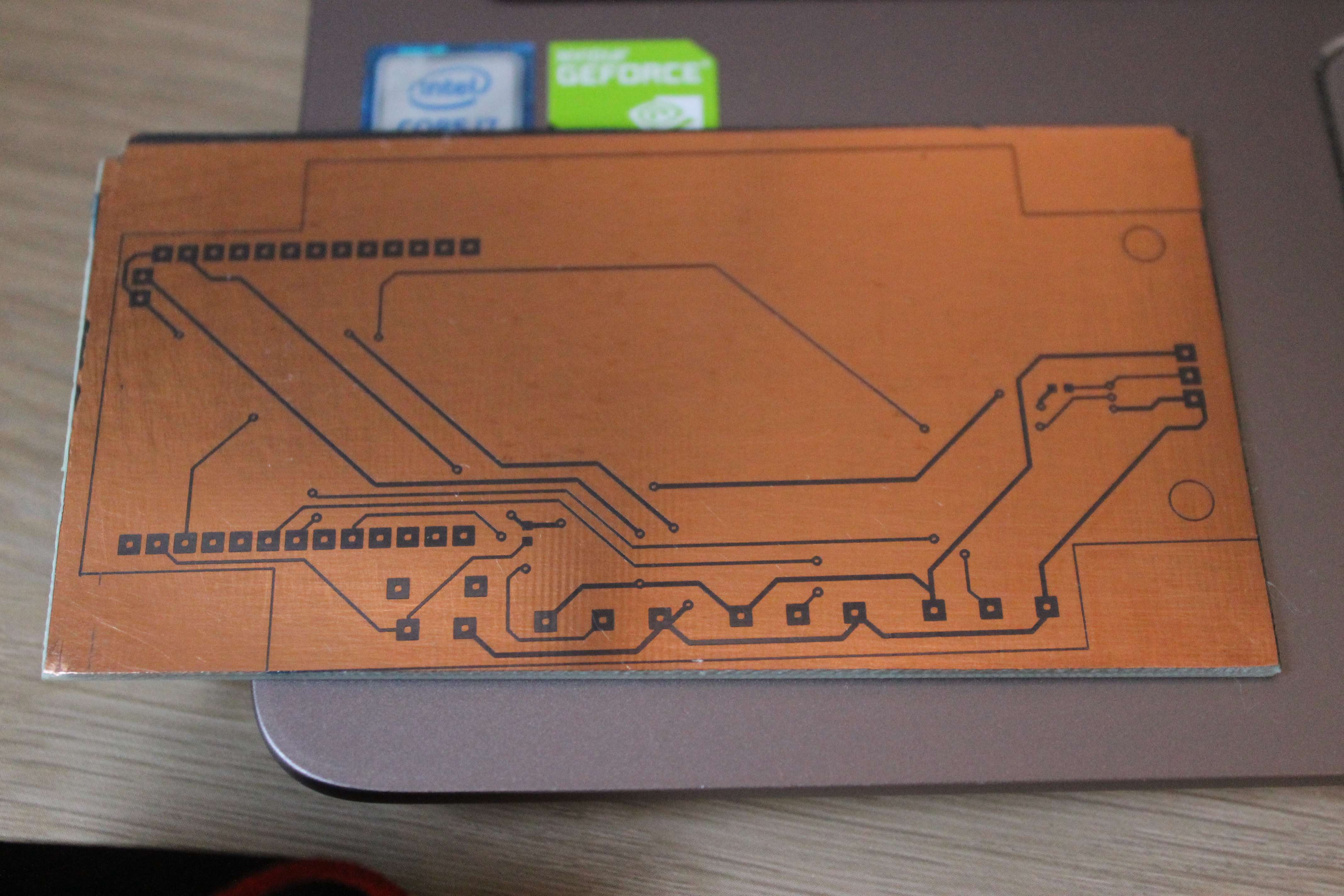
After etching and machining

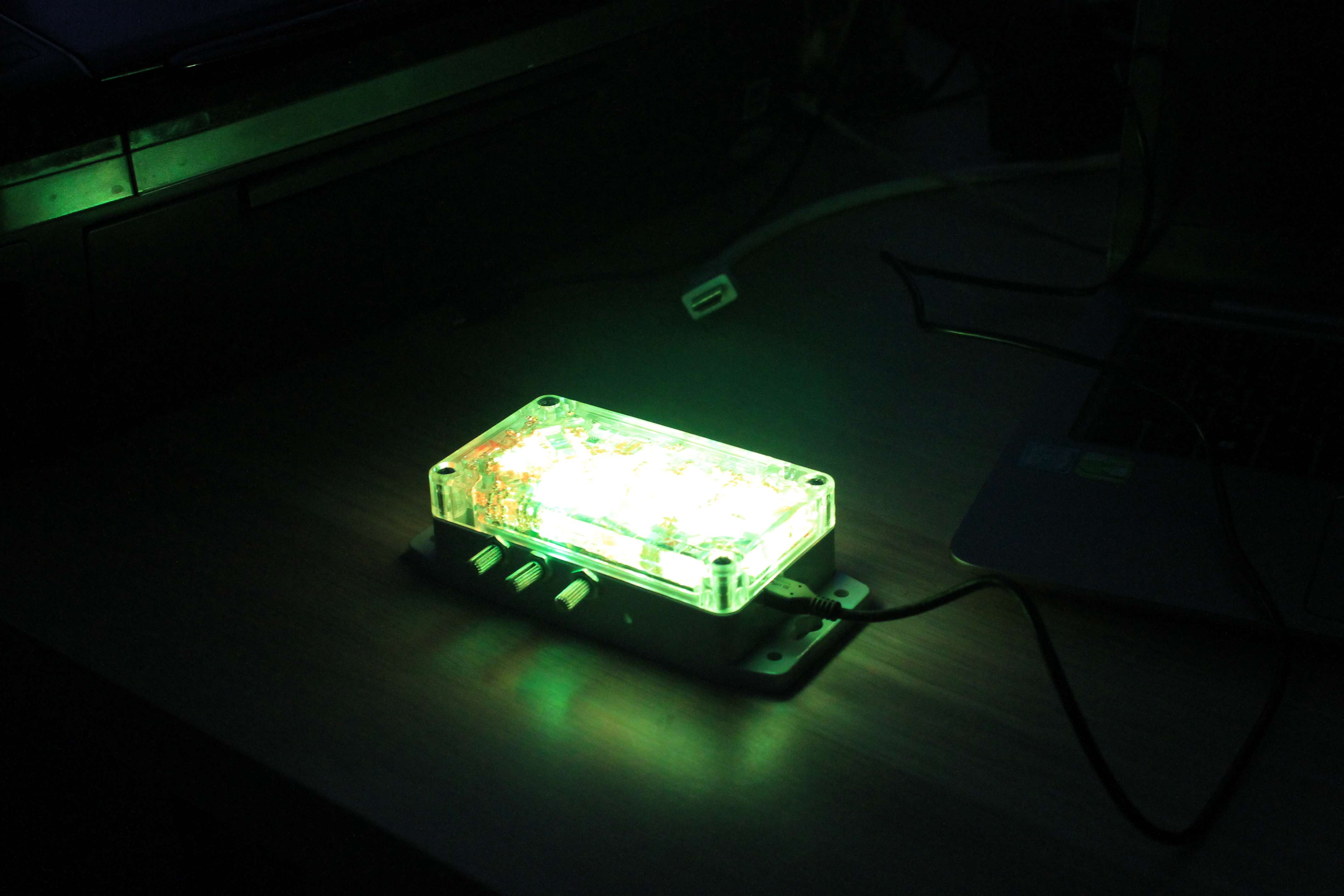
I replaced the module with the microcontroller with its prototype, lying in the closet (because it’s not a pity, but ZUNo should be protected). The first version of ZUNo, but the dimensions are bigger and worse than the antenna, and you can not buy it already. The tests were more or less successful. The last segment had to be soldered. It was originally soldered to the wrong side. And adjust the number of LEDs in the firmware.
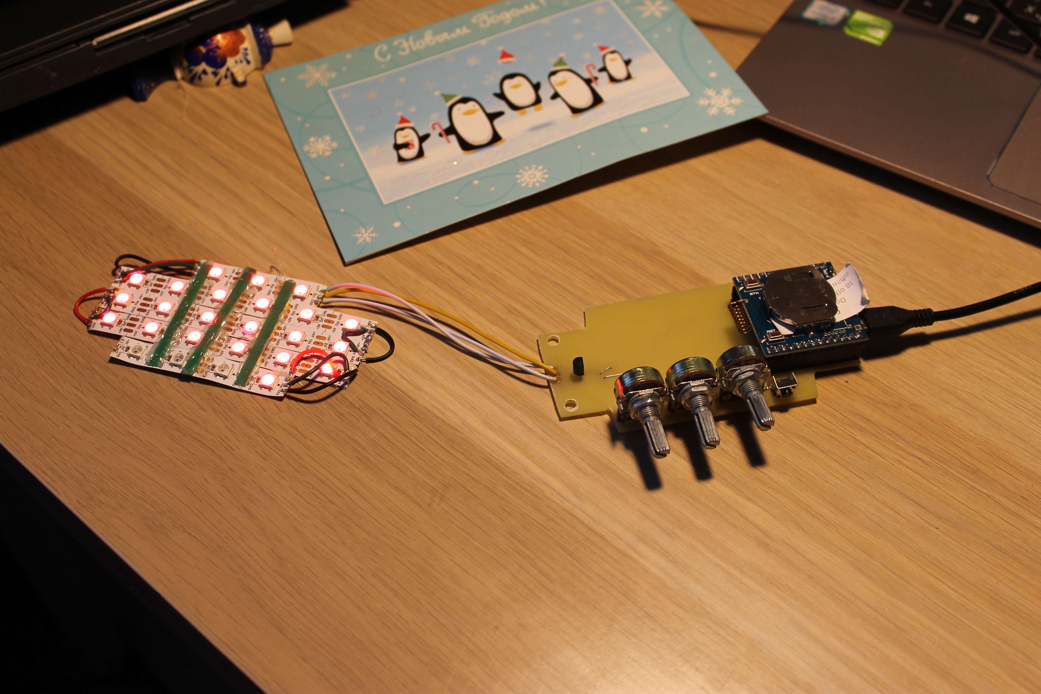
Here's what happened:
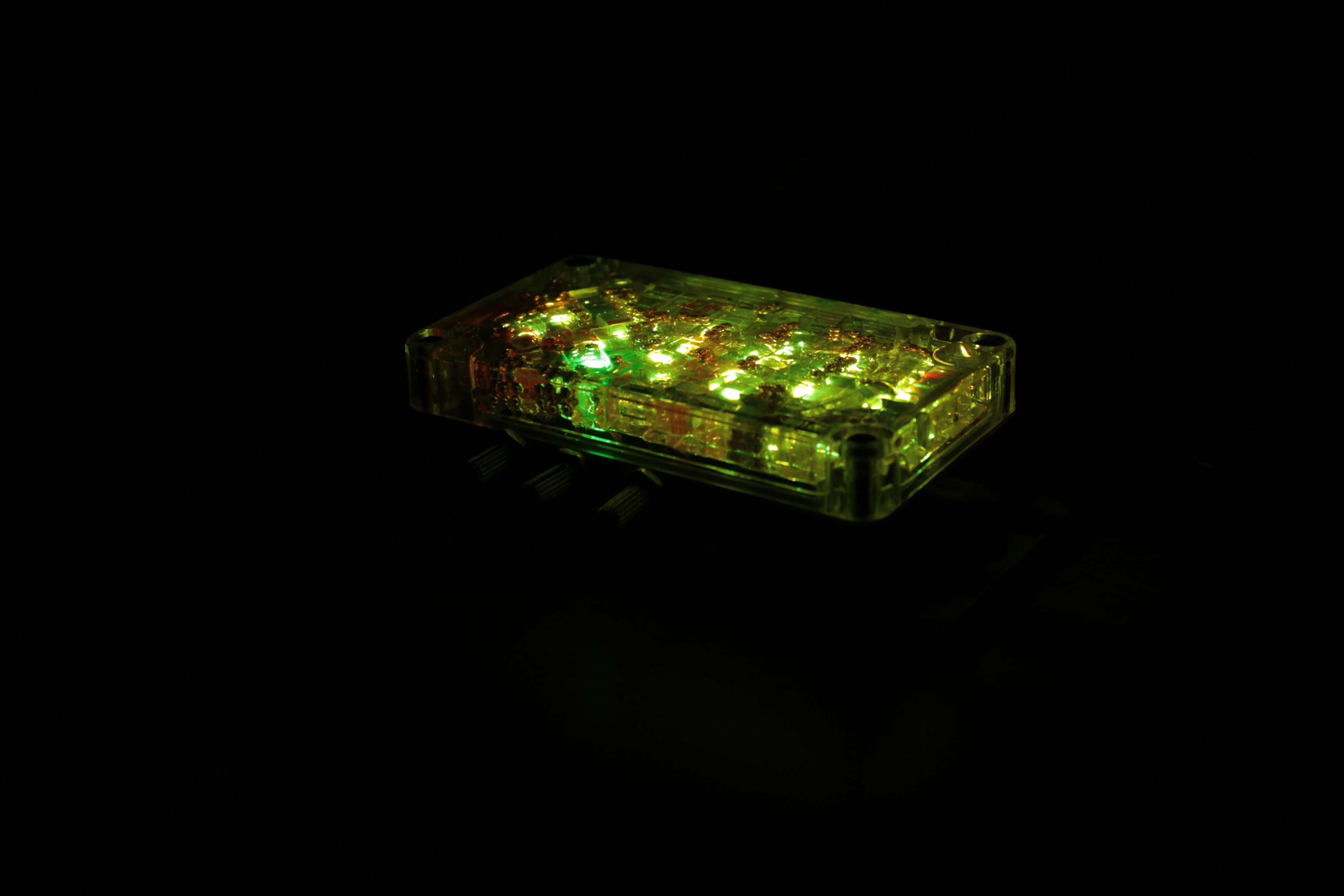
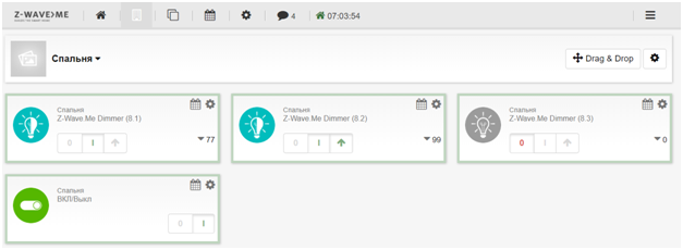
Radio control
Main window with luminaire control channels
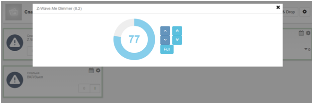
Adjusting the brightness of one channel of the LED strip
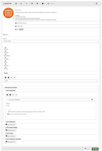
Setting the morning light off
Conclusion
The device is working. It is compact and neat. Powered by charging a mobile phone.
Of the problems seen:
- During the assembly, I cut off some of the tracks on variable resistors, so in manual mode only one channel can be controlled.
- Of the 25 LEDs, only 20 work normally. I have a lot of this, so I will most likely leave it to reveal more serious flaws
Night light sketch
#include"ZUNO_NeoPixel.h"#define MAX_PIXELS 20 // NB! Z-Uno can not control more than 25 WS2811 without harming RF communications#define PIXEL_SIZE 3  // Three colors per pixel#define BUFF_SIZE (MAX_PIXELS * PIXEL_SIZE)
byte pixel_buff[BUFF_SIZE];
NeoPixel pixels(pixel_buff, BUFF_SIZE);
#define B_PRESSED 1#define BUTTON_PIN   1    // Digital IO pin connected to the button.  This will be#define DEF_RED 30#define DEF_GREEN 20
byte red = DEF_RED;
byte green = DEF_GREEN;
byte blue = 0;
#define POWER_ON 1#define POWER_OFF 0
byte light_power = POWER_ON;
byte last_light_power = POWER_OFF;
ZUNO_SETUP_CHANNELS(
      ZUNO_SWITCH_MULTILEVEL(getRed, setRed),
      ZUNO_SWITCH_MULTILEVEL(getGreen, setGreen),
      ZUNO_SWITCH_MULTILEVEL(getBlue, setBlue),
      ZUNO_SWITCH_BINARY(switch_getter, switch_setter)
);
voidswitch_setter(byte value){
  Serial.println("switch");
  Serial.print("value= ");
  Serial.println(value);
  if(value > 1)
    light_power = POWER_ON;
  else
    light_power = POWER_OFF;
}
byte switch_getter(){
  return light_power;
}
intgetRed(){
  return red/2.56;
}
intgetGreen(){
  return green/2.56;
}
intgetBlue(){
  return blue/2.56;
}
voidsetRed(byte value){
  red = value * 2,56;
  for(uint8_t i = 0; i < MAX_PIXELS; i++)
    pixels.setPixelColor(i, pixels.Color(red, green, blue));
  pixels.show();
  Serial.print("set red = ");
  Serial.println(value);
}
voidsetGreen(byte value){
  green = value * 2,56;
  for(uint8_t i = 0; i < MAX_PIXELS; i++)
    pixels.setPixelColor(i, pixels.Color(red, green, blue));
  pixels.show();
  Serial.print("set red = ");
  Serial.println(value);
}
voidsetBlue(byte value){
  blue = value * 2,56;
  for(uint8_t i = 0; i < MAX_PIXELS; i++)
    pixels.setPixelColor(i, pixels.Color(red, green, blue));
  pixels.show();
  Serial.print("set red = ");
  Serial.println(value);
}
voidset_LEDS(){
   for(uint8_t i = 0; i < MAX_PIXELS; i++)
    pixels.setPixelColor(i, pixels.Color(red, green, blue));
   pixels.show();
}
voidread_resistors(){
  red = (analogRead(A0) >> 2) & 0xff;
  green = (analogRead(A1) >> 2) & 0xff;
  blue =  (analogRead(A3) >> 2) & 0xff;
  Serial.print(red);
  Serial.print(" ");
  Serial.print(green);
  Serial.print(" ");
  Serial.print(blue);
  Serial.print(" ");
  Serial.println();
  set_LEDS();
}
#define DEBOUNCE_ACK 10byte check_button(){
  staticbool oldState = HIGH;
  byte debounce_cnt = 0;
  static byte ret = 0;
  if(digitalRead(BUTTON_PIN) == LOW)
  {
    if(ret != B_PRESSED)
      while(digitalRead(BUTTON_PIN) == LOW)
      {
        if(debounce_cnt == DEBOUNCE_ACK)
        {
          ret = B_PRESSED;
          break;
        }
        else
          debounce_cnt++;
       delay(10);
      }
  }
  else
  {
    debounce_cnt = 0;
    ret = 0;
  }
  return ret;
}
voidsetup(){
  Serial.begin(9600);
  pixels.begin();
  pixels.clear();
  pinMode(BUTTON_PIN, INPUT_PULLUP);
}
voidloop(){
  if(check_button() == B_PRESSED)
    read_resistors();
  if(last_light_power != light_power)
  {
    Serial.println("set power");
    if(light_power == POWER_OFF)
    {
      Serial.println("power off");
      red = 0;
      green = 0;
      blue = 0;
    }
    else
    {
      Serial.println("power on");
      red = DEF_RED;
      green = DEF_GREEN;
      blue = 0;
    }
    set_LEDS();
    last_light_power = light_power;
  }
}