 June 15, 2017 at 10:26
Optical character recognition on the microcontroller
Today, optical character recognition is part of the solution of such applied tasks as text recognition and digitization, document recognition, license plate recognition, determining bank card numbers, reading meter readings, determining house numbers for creating maps (Google Street View), etc. d.
Character recognition means the analysis of its image in order to obtain a certain set of signs for comparing them with the signs of the class [ 1 ]. The choice of such a set and the methods for its determination are distinguished by different recognition methods, but for most of them, simultaneous information about all the pixels of the image is needed.
The latter circumstance and a sufficiently large amount of calculations make it impossible to use low-power computing devices (microcontrollers) for optical character recognition. “Yes, and why?”, An informed reader will exclaim, “the power of computing devices is constantly growing, but their price is falling!” [ 2 , 3 ]. Suppose the answer is this: just wondering, is it possible to simplify the recognition method to such an extent that a microcontroller can be used?
It turned out possible, moreover, it turned out to be possible what seems to belong to the field of science fiction, namely:
- recognition regardless of font;
- recognition of a character string without separation into individual characters;
- recognition of “escaped” characters, for example, character in character;
- recognition of "broken" characters;
- recognition of characters consisting of several parts;
- recognition without changing signs when turning up to 15 °. The ability to
recognize rotated characters at a larger angle by changing its features; - character recognition in a video stream from one frame;
- handwriting recognition;
- a limited number of signs for describing a class of characters, for Arabic numerals
and Latin - one, for Cyrillic - a maximum of two (for example, for some
spelling variants F); - simple "manual" definition of features for a new class;
- automatic determination of characteristics for a new class;
- expanding character classes by simply adding features to the database;
And all this on the microcontroller.
The main idea of the method
Now more about the method itself. Consider, for example, the various styles of A:

Despite the visible differences, it is possible to distinguish common signs of a structural type, which are necessary signs of a capital letter A (for unbroken characters), namely: if the symbol in question is a capital letter A, then it will contain a closed region and the region open down.

We emphasize once again that these signs are necessary, but not sufficient: if we describe the contours around two areas of the specified type,

then it will not necessarily be capital letters A, for example, D, Z, R, lowercase handwritten A, are possible ..:

However, the use of areas as elements of a symbol allows you to generate sufficient signs, and for the overwhelming number of alphanumeric characters, you can generate the only sufficient sign! It is very simple to form for each class and, unlike the structural features used by ABBYYTeam for handwriting recognition [ 1 ], its variability is very low and it is possible to form it automatically! In other words, such characters work well for both print and handwritten characters.
Recognition device
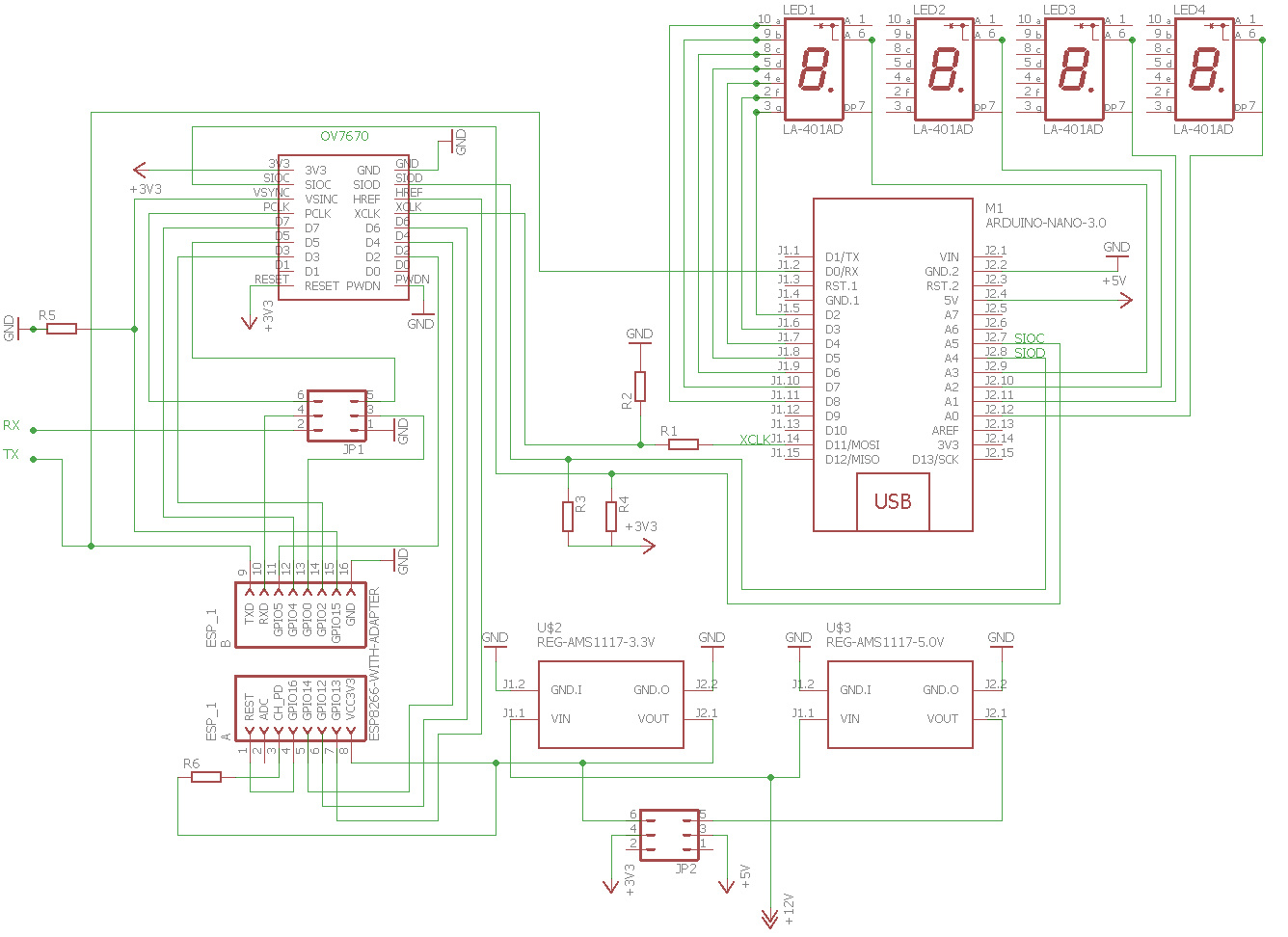
The first test of the method was described in [ 4]. The method was tested on single digits obtained by a primitive camera from a mouse from a seven-segment indicator or printed on paper. After the first success, a natural desire arose to test the possibility of recognizing a sequence of characters, and for this you need to use another camera. We used an OV7670 camera (0.3MP). The remaining main components of the circuit remained unchanged - these are Arduino and ESP8266, but their functions have changed. Arduino is now used to initialize the camera as a master oscillator, receive recognized characters and display them on indicators. ESP8266 is engaged in receiving images from the camera and its recognition, in addition, it provides data transfer to Arduino for display and transmission of recognized information via WiFi to external devices, for example, a smartphone.
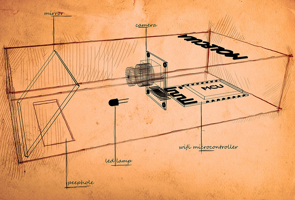
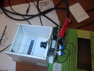
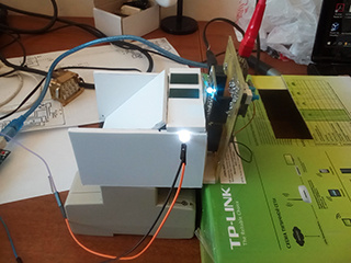
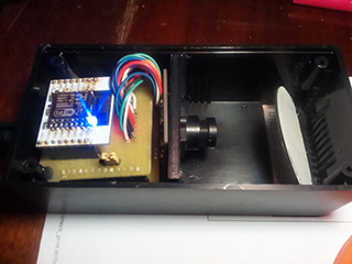
The image enters the device through a slit in its lower part and, reflected from the mirror, enters the camera. The image is illuminated by an LED through the same mirror. The mechanical circuit of the device is shown in the figure.
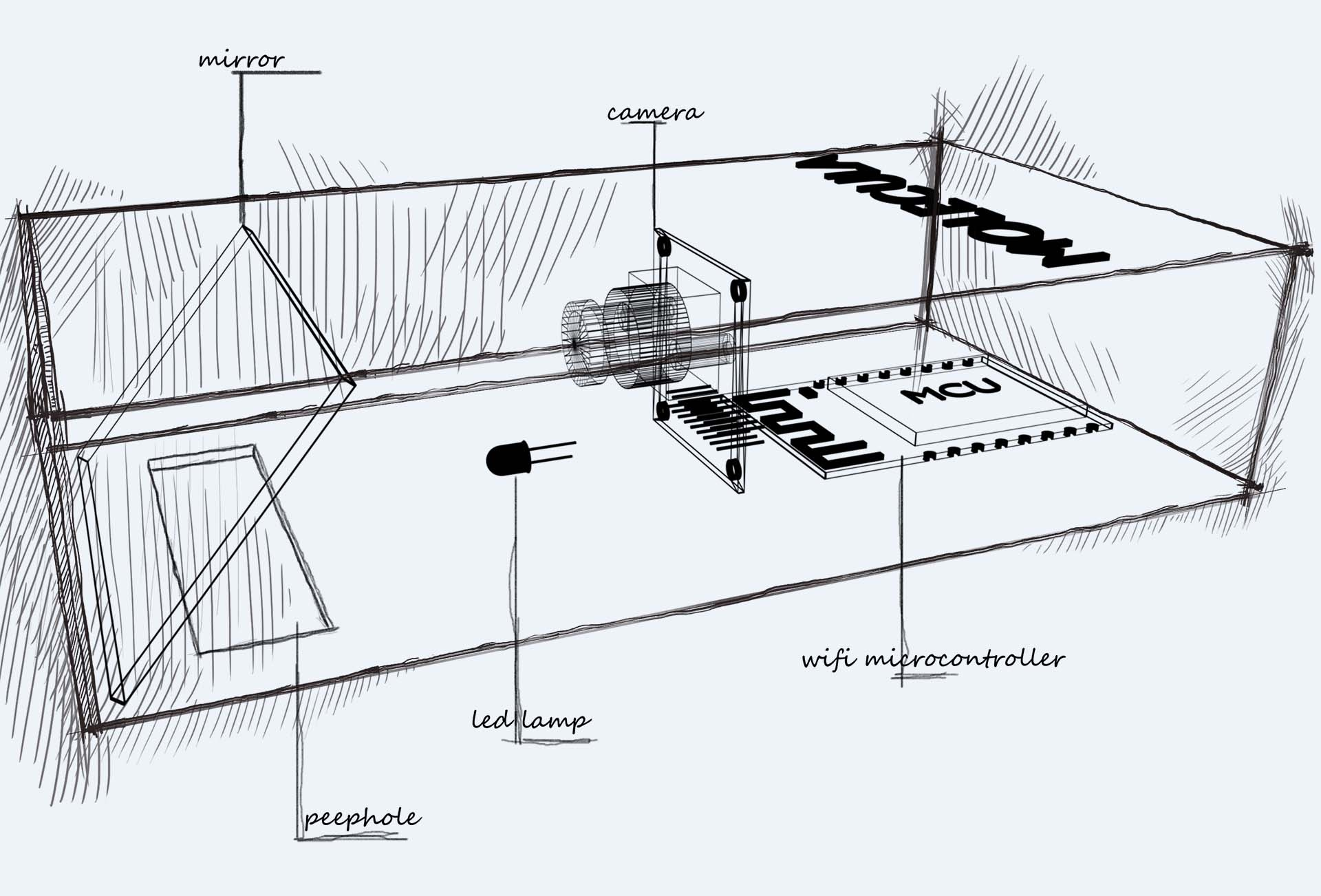
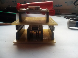
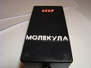
Photo of the working prototype
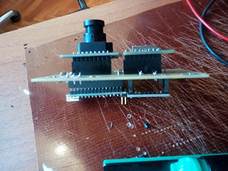

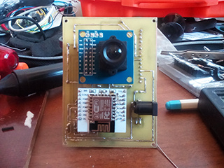
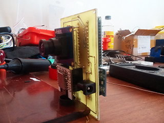
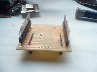
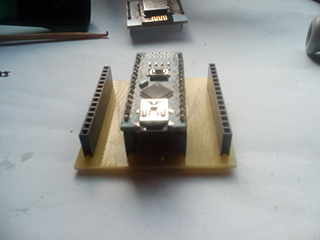
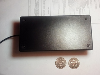
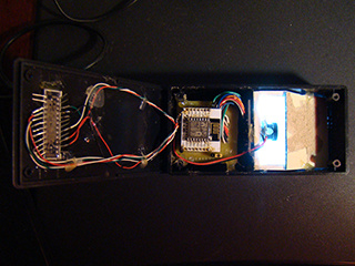

The first version of the working prototype:
The second version of the working prototype:
Getting images on the ESP8266
Camera settings during initialization are taken from [ 5 ]. The frame rate is approximately 0.4 fps. Since the number of pins on the ESP8266 is not enough, only the 6 most significant bits of each brightness byte of the image are processed (the camera is configured in YUV mode). To obtain an image, a finite state machine (state machine) is used.

According to OV7670 camera datasheet [ 6 ]


The following camera conditions, conditions and signals during its operation can be distinguished:
| Status Name, Number | Status Description | Signal to transition to another state |
| camoff, 0 | the camera is not ready for work | vzz (vsync = 1, href = 0, pclk = 0) |
| frapause 1 | pause between frames. waiting for the start of the frame. | zzz (vsync = 0, href = 0, pclk = 0) |
| framebeg, 2 | reading frame. waiting for the start of a line in a frame. | zhz (vsync = 0, href = 1, pclk = 0) |
| framebeg, 2 | reading frame. waiting for the end of the frame after reading the last pixel | vzz (vsync = 1, href = 0, pclk = 0) |
| fbyteread, 3 | brightness byte read. waiting for a pause before the color difference byte. | zhz (vsync = 0, href = 1, pclk = 0) |
| fpause 4 | pause before color difference byte. waiting for the start of reading the color difference byte. | zhp (vsync = 0, href = 1, pclk = 1) |
| sbyteread, 5 | color difference byte read. waiting for a pause before the brightness byte. | zhz (vsync = 0, href = 1, pclk = 0) |
| spause, 6 | pause before luminance byte. waiting for the end of the line. | zzz (vsync = 0, href = 0, pclk = 0) |
| spause, 6 | pause before luminance byte. waiting for the start of reading the brightness byte. | zhp (vsync = 0, href = 1, pclk = 1) |
The implementation of the machine is based on the same principles that are described in [ 7 ]. The whole machine is described by its gene - a three-dimensional vector, the first component of which contains keys, and the second - the names of new states, the third - the names of functions. The key contains information from the current state and the transition signal. To generate the key and signal, bit operations are used. Implementation details are clear from the camera reader module code.
user_main.c
#include "ets_sys.h"
#include "osapi.h"
#include "os_type.h"
#include
#include "driver/uart_register.h"
#include "user_config.h"
#include "user_interface.h"
#include "driver/uart.h"
#include "readCam.h"
#define DELAY 5000 /* milliseconds */
LOCAL os_timer_t cam_timer;
uint16_t frN;
extern uint8_t pixVal;
uint8_t rN[10];
LOCAL void ICACHE_FLASH_ATTR getNFrame(void *arg){
  uint16_t sig, sV,sH,sP;
  uint16_t pVal;
  uint16_t d7,d6,d5,d4,d3,d2;
  stateMashine camSM;
  ets_uart_printf("getNFrame...\r\n");
  initSMcm(&camSM);
  while(frN<20){
	  system_soft_wdt_feed();
	  pVal= *GPIO_IN;
	  sV=((pVal&(1UL<>VSYNC);
	  sH=((pVal&(1UL<>HREF);
	  sP=((pVal&(1UL<>PCLK);
	  sig=4*sV+2*sH+sP*sH;
	  d7=((pVal&(1UL<>D7);
	  d6=((pVal&(1UL<>D6);
	  d5=((pVal&(1UL<>D5);
	  d4=((pVal&(1UL<>D4);
	  d3=((pVal&(1UL<>D3);
	  d2=((pVal&(1UL<>D2);
	  pixVal=128*d7+64*d6+32*d5+16*d4+8*d3+4*d2;
	  exCAM(&camSM,sig,&frN,rN);
	 }
}
uint32 ICACHE_FLASH_ATTR user_rf_cal_sector_set(void)
{
    enum flash_size_map size_map = system_get_flash_size_map();
    uint32 rf_cal_sec = 0;
    switch (size_map) {
        case FLASH_SIZE_4M_MAP_256_256:
            rf_cal_sec = 128 - 8;
            break;
        case FLASH_SIZE_8M_MAP_512_512:
            rf_cal_sec = 256 - 5;
            break;
        case FLASH_SIZE_16M_MAP_512_512:
        case FLASH_SIZE_16M_MAP_1024_1024:
            rf_cal_sec = 512 - 5;
            break;
        case FLASH_SIZE_32M_MAP_512_512:
        case FLASH_SIZE_32M_MAP_1024_1024:
            rf_cal_sec = 1024 - 5;
            break;
        default:
            rf_cal_sec = 0;
            break;
    }
    return rf_cal_sec;
}
void ICACHE_FLASH_ATTR user_init(void){
	void (*cbGetFrame)(void *arg);
	cbGetFrame=(void*)getNFrame;
	UARTInit(BIT_RATE_921600);
	user_gpio_init();
	os_timer_disarm(&cam_timer);
	os_timer_setfn(&cam_timer, (os_timer_func_t *)cbGetFrame, NULL);
	os_timer_arm(&cam_timer, DELAY, 0);
}
readCam.h
#ifndef INCLUDE_READCAM_H_
#define INCLUDE_READCAM_H_
#define GPIO_IN 				((volatile uint32_t*) 0x60000318)
#define WP 		320
#define HP 		240
#define PIXTYP 0
//image __________________________________________
#define IMAGEY0 60
#define IMAGEH HP/3
//____________________pins_____________________
#define VSYNC 15
#define HREF 13
#define PCLK 3
#define D7 4
#define D6 12
#define D5 0
#define D4 14
#define D3 2
#define D2 5
//*************signals OV7670*****************
#define ZZZ 0
#define VZZ 4
#define ZHZ 2
#define ZHP 3
//*************states OV7670*******************
#define CAMOFF 0
#define FRAPAUSE 1
#define FRAMEBEG 2
#define FBYTEREAD 3
#define FPAUSE 4
#define SBYTEREAD 5
#define SPAUSE 6
#define SSCC 40//max state_signal_condition count
#define STATE_L 5
#define STATE_V 0x1F
#define SIG_L 8
#define SIG_V 0xFF
typedef struct {
	uint8 pix[WP] ;
}linePixel;
typedef struct gen{
	uint8_t state;
	uint8_t sig;
	uint8_t stateX;
	void *fp;
}gen;
typedef struct stateMashine{
	uint8_t count;
	uint16_t ssc[SSCC];
	uint8_t stateX[SSCC];
	void *fPoint[SSCC];
	void *fpd;
}stateMashine;
#endif /* INCLUDE_READCAM_H_ */
readCam.c
#include "ets_sys.h"
#include "osapi.h"
#include "os_type.h"
#include
#include "driver/uart_register.h"
#include "user_config.h"
#include "user_interface.h"
#include "driver/uart.h"
#include "readCam.h"
void sendLine(uint16_t lN);
void ICACHE_FLASH_ATTR sendFramMark(void);
void ICACHE_FLASH_ATTR sendCtr3Byte(uint8_t typ,uint16_t len);
void user_gpio_init(void);
void sendByte(uint8_t bt);
void  ICACHE_FLASH_ATTR initSMcm(stateMashine *psm);
void exCAM( stateMashine *psm,uint8_t sig,uint16_t *frameN,uint8_t *rN);
int   indexOf(stateMashine *psm,uint16_t ssc);
linePixel lp;
uint8_t pixVal;
void exCAM( stateMashine *psm,uint8_t sig,uint16_t *frameN,uint8_t *rN){
	 int16_t ind;
	 uint16_t lN;
	 uint16_t pN;
	 static uint8_t state=CAMOFF,stateX=CAMOFF;
	 static void (*pfun)()=NULL;
	 uint16_t stateSigCond=0;
	 stateSigCond|=((state&STATE_V)<<(16-STATE_L))|((sig&SIG_V)<<(16-STATE_L-SIG_L));
	 ind=indexOf(psm,stateSigCond);
	 if(ind>-1)	 stateX=(*psm).stateX[ind];
	 if(ind>-1)	 pfun=(*psm).fPoint[ind];
	 else pfun=(*psm).fpd;
	 pfun(frameN,&lN,&pN,rN);
	 state=stateX;
}
void  _cm0(){}
void  _cm1(uint16_t *fN,uint16_t *lN,uint16_t *pN){//new frame
	sendFramMark();
	sendCtr3Byte(PIXTYP,0);
	(*lN)=0;
}
void  _cm2(uint16_t *fN,uint16_t *lN,uint16_t *pN){//frame end
	if(*lN==HP-1)(*fN)++;
}
void  _cm3(uint16_t *fN,uint16_t *lN,uint16_t *pN){//new line
	uint16_t pixN;
	 (*pN)=0;
	 //	pixN=(*pN);//right image
	 pixN=WP-1-(*pN);//revers image
	 (lp).pix[pixN]=pixVal;
	 (*pN)++;
}
void  _cm4(uint16_t *fN,uint16_t *lN,uint16_t *pN){// first byte
	uint16_t pixN;
//	pixN=(*pN);//right image
	pixN=WP-1-(*pN);//reverse image
	(lp).pix[pixN]=pixVal;
//	if(pixN>UART_TXFIFO_CNT_S)
					& UART_TXFIFO_CNT;
	}
		buf[lenBuff] =bt;
		uart0_tx_buffer(buf, lenBuff + 1);
}
void  sendLine(uint16_t lN){
	uint16_t j;
	uint8_t sByt;
	for(j=0;j(IMAGEY0+IMAGEH))sByt=0xFF;
		sendByte(sByt);
	}
}
void ICACHE_FLASH_ATTR user_gpio_init(void) {
	ets_uart_printf("GPIO  initialisation...\r\n");
	PIN_FUNC_SELECT(PERIPHS_IO_MUX_GPIO0_U, FUNC_GPIO0);
	gpio_output_set(0, 0, 0, BIT0); // Set GPIO0 as input
	PIN_FUNC_SELECT(PERIPHS_IO_MUX_GPIO2_U, FUNC_GPIO2);
	gpio_output_set(0, 0, 0, BIT2); // Set GPIO2 as input
	PIN_FUNC_SELECT(PERIPHS_IO_MUX_U0RXD_U, FUNC_GPIO3);
	gpio_output_set(0, 0, 0, BIT3); // Set GPIO3 as input
	PIN_FUNC_SELECT(PERIPHS_IO_MUX_GPIO4_U, FUNC_GPIO4);
	gpio_output_set(0, 0, 0, BIT4); // Set GPIO4 as input
	PIN_FUNC_SELECT(PERIPHS_IO_MUX_GPIO5_U, FUNC_GPIO5);
	gpio_output_set(0, 0, 0, BIT5); // Set GPIO5 as input
	PIN_FUNC_SELECT(PERIPHS_IO_MUX_MTDI_U, FUNC_GPIO12);
	gpio_output_set(0, 0, 0, BIT1); // Set GPIO13 as input
	PIN_FUNC_SELECT(PERIPHS_IO_MUX_MTMS_U, FUNC_GPIO14);
	gpio_output_set(0, 0, 0, BIT14); // Set GPIO14 as input
	PIN_FUNC_SELECT(PERIPHS_IO_MUX_MTCK_U, FUNC_GPIO13); // Set GPIO13 function
	gpio_output_set(0, 0, 0, BIT13); // Set GPIO13 as input
	PIN_FUNC_SELECT(PERIPHS_IO_MUX_MTDO_U, FUNC_GPIO15);
	gpio_output_set(0, 0, 0, BIT15); // Set GPIO15 as input
	ets_uart_printf("...init done!\r\n");
}
void ICACHE_FLASH_ATTR sendFramMark(void){
	sendByte(42);
	sendByte(42);
}
void ICACHE_FLASH_ATTR sendCtr3Byte(uint8_t typ,uint16_t len){
	uint8_t lLen,hLen;
	sendByte(typ);
	lLen=len&0xFF;
	hLen=(len&(0xFF<<8))>>8;
	sendByte(lLen);
	sendByte(hLen);
}
Image processing
Image processing consists of line-by-line binarization, combining the obtained segments, analysis and synthesis of the obtained figures. The purpose of processing is the formation of integral features, including the properties of the areas included in the figures. Despite the simplicity of the main idea, its implementation contains a number of specific points that cannot be disclosed in the framework of this article.
Recognition process visualization
To debug the recognition process, we used the visualization on the PC of the source image, the binarized image, and the image that the microcontroller “sees” or “understands”. Despite the fact that the latter does not greatly please our eyes, its details are enough to recognize the symbols. The figure shows examples of visualization.


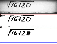
It should be noted that sometimes due to camera synchronization errors, situations arise when lines with color difference rather than brightness bytes appear in the original picture. In this case, the picture is blurred and recognition does not occur. The task of handling such situations at the present stage was not posed.

Also, recognition does not occur if the text is incorrectly positioned:
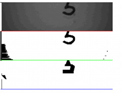
For visualization, we used a small program written in Java Script using nodeWebkit.
app.js
* to work with a COM port, you need to assemble the nodeJS "serialport" module under nodewebkit
var btn = document.getElementById('com');
var gui = require("nw.gui");
var select_com = document.getElementById('select_com');
var bdr = document.getElementById('bdr');
var canvas = document.getElementById('canvas');
var dev = document.getElementById('dev');
var ctx = canvas.getContext('2d');
var width = 320,
    height = 240;
var byteCount = (width * height)/3;
var lastStr=byteCount-width;
var dataArr;
var dataStr;
var indArr = 0;
var dataArrLen = 0;
var byteCounter = 0;
var newStr = 0;
var sendTyp=0;
document.addEventListener('DOMContentLoaded', function() {
    btn.addEventListener('click', function() {
        connectCom(function(vector) {
            drawImg(vector);
        });
    });
    dev.addEventListener('click', function(){
             var win = gui.Window.get();
             win.showDevTools();
    });
});
function drawImg(imgArr) {
    var imgData = ctx.createImageData(width, height);
    var ind;
     for (var i = 0; i < imgArr.length; i++) {
            imgData.data[4 * i] = imgArr[i];
            imgData.data[4 * i + 1] = imgArr[i];
            imgData.data[4 * i + 2] = imgArr[i];
            imgData.data[4 * i + 3] = 255;
        if(ilastStr){ //red line
            imgData.data[4 * i] = 255;
            imgData.data[4 * i + 1] = 0;
            imgData.data[4 * i + 2] = 0;
            imgData.data[4 * i + 3] = 255;
        }
        if(i<2*byteCount&&i>byteCount+lastStr){ //green line
            imgData.data[4 * i] = 0;
            imgData.data[4 * i + 1] = 255;
            imgData.data[4 * i + 2] = 0;
            imgData.data[4 * i + 3] = 255;
        }
        if(i<3*byteCount&&i>2*byteCount+lastStr){ //blue line
            imgData.data[4 * i] = 0;
            imgData.data[4 * i + 1] = 0;
            imgData.data[4 * i + 2] = 255;
            imgData.data[4 * i + 3] = 255;
        }
    }
    ctx.putImageData(imgData, 0, 0);
    imgArr.length=0;
}
function connectCom(callback) {
    const PIXTYPE=0,BINTYPE=1,FIGTYPE=2;
    var imgTyp=PIXTYPE;
    var  serialport = require('serialport');
    var imgArr = [];
    var framCount=0,strNum,colNum;
    var pix=false;
    var comm = 'COM' + select_com.value;
    var boudrate = +bdr.value;
    var SerialPort = serialport.SerialPort;
    var port = new SerialPort(comm, {
        baudRate: boudrate,
        dataBits: 8,
        stopBits: 1,
        parity: "none",
        bufferSize: 65536,
        parser: SerialPort.parsers.byteLength(1)
    });
    port.on('open', function() {
        console.log('Port ' + comm + ' Open');
    });
    port.on('data', function(data) {
        if(imgTyp==PIXTYPE||imgTyp==BINTYPE){
            if (data[0] == 42 && newStr == 0) {
                newStr = 1;
                data[0]=255;
            }
            if (newStr == 1 && data[0] == 42) {
                newStr = 2;
            }
            if (newStr == 2 && byteCounter <2*byteCount) {
                colNum=byteCounter%width;
                strNum=(byteCounter-colNum)/width;
                if(strNum%2==0){
                    imgArr[(strNum/2)*width+colNum]=data[0];
                }
                if(strNum%2==1){
                    imgArr[((strNum-1)/2)*width+byteCount+colNum]=data[0];
                }
                 byteCounter++;
            }
            if (newStr == 2 && byteCounter == 2*byteCount) {
                newStr = 0;
                byteCounter = 0;
                framCount++;
                console.log('Frame Num ', framCount);
                imgTyp=FIGTYPE;
             }
        }
          if(imgTyp==FIGTYPE){
            if (data[0] == 42 && newStr == 0) {
                newStr = 1;
                data[0]=255;
            }
            if (newStr == 1 && data[0] == 42) {
                newStr = 2;
            }
            if (newStr == 2 && byteCounter < byteCount) {
                imgArr[byteCounter+2*byteCount] = data[0];
                byteCounter++;
            }
            if (newStr == 2 && byteCounter == byteCount) {
                newStr = 0;
                byteCounter = 0;
                framCount++;
                console.log('Frame Num ', framCount);
                imgTyp=PIXTYPE;
                 callback(imgArr);
            }
        }
    });
    port.on('error', function() {
        alert('Ошибка подключения к порту СОМ');
    });
}
An example of the operation of the device is shown in a short video.
Video with prototype No. 1
Video with prototype No. 2
Conclusion
The results obtained show the high efficiency of the recognition method on devices that would seem completely unintended for this. A small improvement of the method associated with the use of information from several frames for additional “peering” into the areas of interest will allow us to raise the quality of recognition to the level of commercial products.
The approach for analyzing and recognizing multi-character objects, such as handwritten text strings or hieroglyphics, is also understandable, but for this we need devices with a larger memory capacity than our esp (512K, program volume more than 250K).
Thanks for attention.
Links:
1. Text recognition in ABBYY FineReader (2/2)
2.Omega2: the smallest microcomputer in the world with Linux and Wi-Fi
3. Orange Pi 2G-IoT is the ideal single-board for IoT
4. Digit recognition on the microcontroller
5. Arduino sketch for working with the OV7670 camera
6. OV7670 camera dataset
7. Dynamics reflection in ACS models









