DIY KVM IP
- From the sandbox
- Tutorial
This article was written under the impression of another - many thanks to the author! In this article, I almost managed to make my own IP KVM Switch, and that's cool! But I will explain why almost. Yes, everything works there as the author wrote ... Until the reboot into the BIOS, all the magic is scattered there and no matter how hard you try, nothing happens.
It was decided to correct this annoying misunderstanding and as cheaply and compactly as possible. Let's start with the stereotypes of Raspberry Pi and Arduino, and the next article will continue on another hardware.
So, what we need:
1. A video capture card is mandatory with support for the UVC driver, like this one. The options are
full on aliexpress and other Chinese stores.
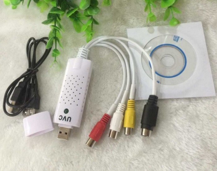
UVC is a standardized open source driver that is included by default in most Linux distributions; there may be problems with other drivers.
2. VGA to AV Converter:
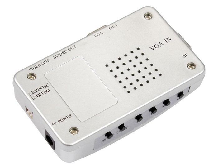

Pay attention! What is needed is VGA to AV, and not vice versa.
3. Arduino UNO, namely UNO, since it has an Atmega16u2 chip, it interests us first of all. Here it is next to the USB port, there are also arduins with the Atmega8u2 chip that will suit both.

four. And of course Raspberry Pi, I had version 2 b, so everything written in this article is relevant for him, but in general I think there should not be any special difficulties with other raspberry models.
Well, the input is given, let's get started. I used the 2015-05-05-raspbian-wheezy distribution, probably it doesn’t matter, further manipulations should be suitable for any distribution based on Debian.
We connect the video capture card to the burberry, it is better to connect it directly to USB without using USB extension cables, especially the one that comes with the board, otherwise video braking, freezing of the burberry, etc. may occur.
Go to the console, update packages:
We check whether the board has determined:
It should produce something like: / dev / video0.
We set Motion, we will transmit the captured image through it:
Edit autorun config:
In the line
Edit the config of motion itself (a):
Change the parameter values as follows:
The parameter determines the launch of the application as a service:
These parameters determine the resolution of the transmitted image, it makes no sense to set a higher resolution, because video capture is limited to PAL or SECAM standards, the resolution of which is 720x576. This incidentally is an annoying flaw, but more on that later.
Frame Rate:
Disable saving screenshots:
Image Transmission Quality:
Frame Rate:
Removing restrictions on connecting from other ip
Save the changes Ctrl + x, y, Enter.
Reboot the crack:
We are waiting for a couple of minutes if everything is done correctly, the LED on the video capture board should light up.
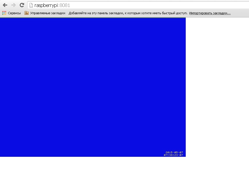
We connect the browser to port 8081 raspberry and we see a gray or blue rectangle with time running from below.
The process has begun, we are looking for a victim to capture the signal from the VGA port, we connect to the converter “VGA IN” port, and the video capture card to “VIDEO OUT”. It should be something like this, don’t be afraid I have a bad cable, so the image is “double”, I tried with another image was better, but the resolution can not be changed. 720x576 is the limitation of the converter and the video capture card, which, with all desire, can not be overcome.

Well learned to transmit the image, it remains the case for small - to transfer control.
For this, you guessed it, we will use arduino. The choice fell on the Arduino UNO for a reason, there is a very necessary chip for our purposes called Atmega16u2, only thanks to it I managed to get the BIOS of the computer to identify arduino as a USB keyboard. By default, as part of the arduino board, this chip acts as a USB to Serial converter for uploading firmware to the Atmega328p microcontroller, a large rectangular chip on the arduino board. In fact, Atmega16u2 is the same microcontroller, but with an important difference, it is able to directly work with the USB bus. Atmega16u2, with the necessary firmware, can emulate almost any USB device. Do you understand what I'm leading to? We will sew this miracle of engineering and force us to work for the good of society.
On the Internet, a firmware was found that turns Atmega16u2 into a USB keyboard that accepts commands of a certain type through the Serial Port.
The instructions in this article are written for windows, Linuxsoids can take advantage of this .
And so let's proceed, for the firmware you will need a utility from the manufacturer called Flip . We download, install, launch, and here we have the program window:

First, the buttons (daws) are not active, this is normal, we connect the arduino to the computer and close - we open the two extreme contacts from the USB port, RESET and GND.
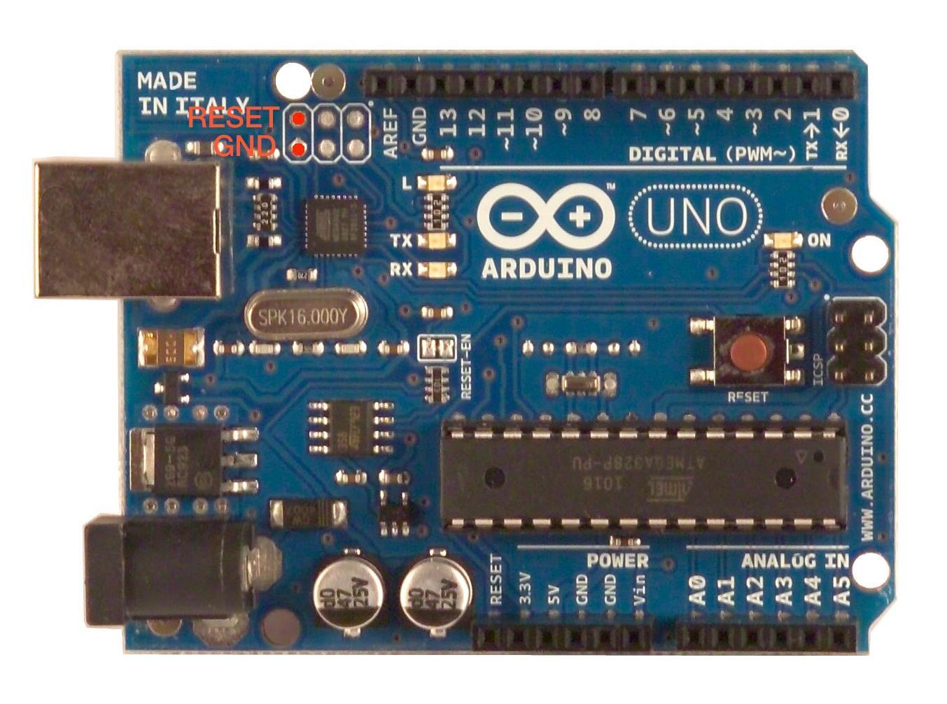
Strange as it may seem, a new device should appear in the system, ATmega16u2 install the driver (in the program folder), select the tab “Settings” → “Communication” → “USB” → “open” in the flip program, the buttons should become active. Just in case, you can backup the firmware so that everything can be returned to its place. In the “File” menu, click “Load HEX File”, the program is demanding on paths, it is best to put the firmware file in the root of the C: drive, select the desired hex file with the firmware, check if the “Erase”, “Program”, “Verify” daws and click "Run." Disconnect - connect arduino and voila ... Now we can no longer download firmware to arduino via the built-in USB, but we got an excellent keyboard without buttons.
Do not worry about arduino firmware, the firmware can be downloaded from the Arduino IDE via a separate USB To TTL adapter, although I must say, now it will be less convenient.
We connect the USB To TTL adapter, for example, this:
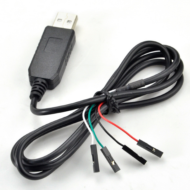
We need White, green and black contacts, these are RX, TX and GND, respectively, we connect them to the pins with the same designations on the arduino, only vice versa RX to TX, and TX to RX. Red contact should not be used!
We connect USB To TTL to the computer, install the driver, a new COM Port should appear in the device manager. Open the arduino IDE and expose: Board - Arduino / Genuino Uno, Port - our new serial port.
Add the necessary library to the arduino IDE: Follow the link github.com/SFE-Chris/UNO-HIDKeyboard-Library click "Clone or download" → "Download ZIP". then in the arduino IDE, select the “Sketch” tab → “Connect library” → “Add .ZIP library” and select the just downloaded zip archive.
Preparation is complete, go directly to the firmware. Copy my scribble:
insert into arduino IDE and press the check button. Right now the most crucial stage will begin, here the most important thing is to catch the moment, few people get it right the first time. We press the download button in the arduino IDE, first the white lines with the compilation log will run, orange will follow, this is the connection to the serial port, this is the moment you need to catch and manage to press the RESET button on the arduino board. The firmware download should happen, if everything is successful, you will see an inscription like this
If after several attempts the firmware download did not happen, try swapping the RX and TX contacts, and also check if the GND pin is connected securely.
We open the console on raspberry and write:
The raspberry settings menu opens, select “Advanced Options” → “Serial” and select “No”.
Perhaps these manipulations will not be needed, so reinsurance. This parameter determines whether the OS on raspberries will interact with the serial port, this interaction is mainly needed for debugging, so we can safely disable it, it will only interfere with us, because we will communicate with arduino through this port, and the system will clog the ether.
Install the minicom program.
Minicom is a simple program for working with serial port.
We set access rights to the device, / dev / ttyAMA0 is the same serial port.
We start minicom:
The program menu will open, select the “Serial port setup” item, another menu will open, select the “Serial Device” by pressing the A key, prescribe / dev / ttyAMA0, press Enter, then select the Bps / Par / Bits item under the letter E, the next one appears press C and Q on the menu bar Current: it should look like this: “9600 8N1” press Enter. Make sure that the lines F - Hardware Flow Control: and G - Software Flow Control: are No, in general, everything should be as in the screenshot below, press Enter.

Save these settings as the default settings “Save setup as dfl” and close “Exit from Minicom”.
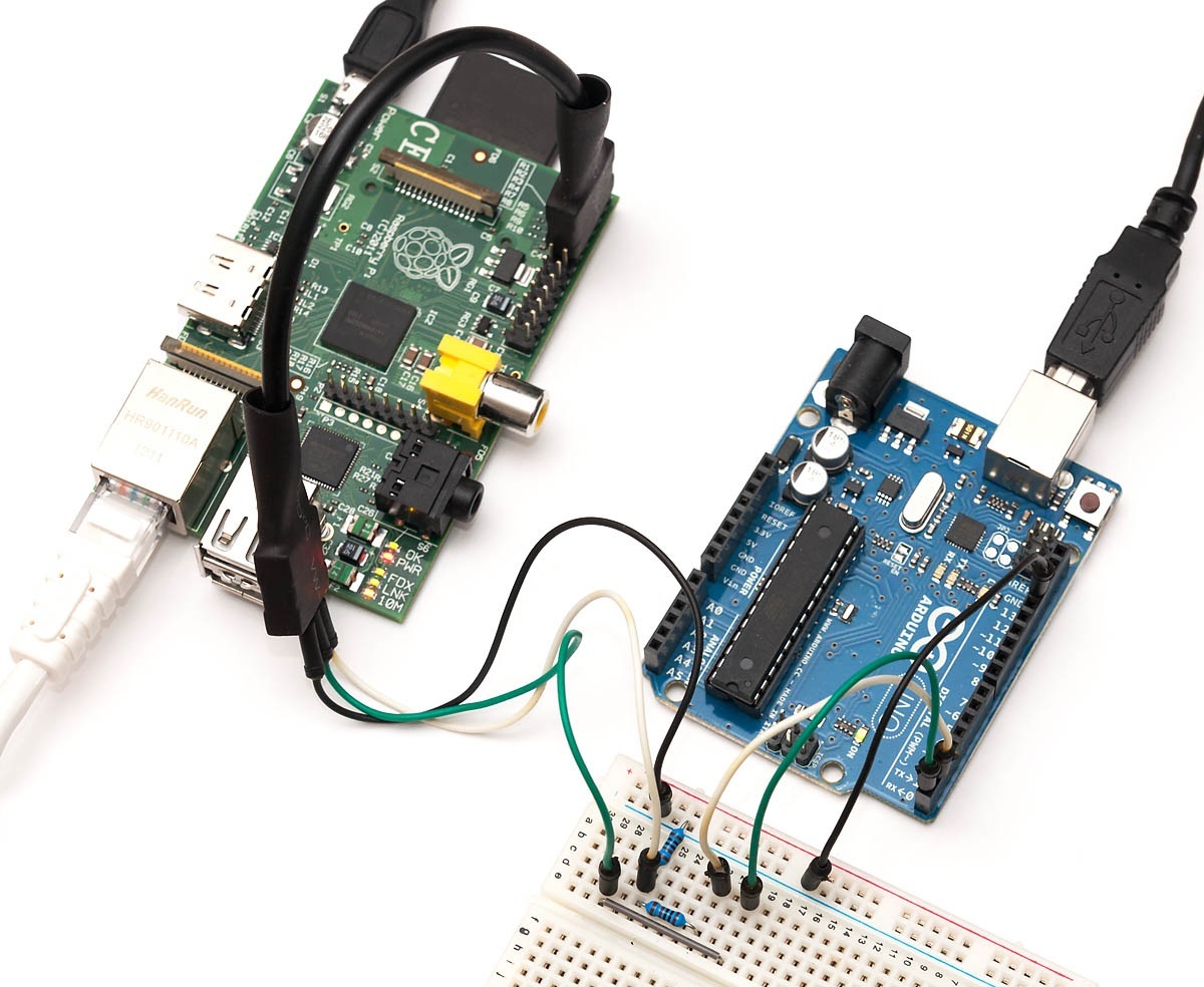
We move on, now we are almost ready, it remains only to connect the arduino to the raspberry serial port, something like this:

There is one point here, arduino and raspberry are different voltage levels and in theory they need to be coordinated, I advise you to read the article .
Although everything worked directly for me without coordination, I should not imitate a bad example and purchase a logic level converter, the simplest one looks like this:

Or at least assemble a voltage divider on resistors.
Everything is ready, you can begin.
We check all the connections, turn on raspberry pi, go to the raspberry console, run minicom. Immediately make a reservation, I connected to raspberries through ssh, I used KiTTY (a modified version of PuTTY) as a client, this is important because with other terminals, the values of the transmitted keys may be different, and accordingly, it will be necessary to make a correction for the wind - change the switch case switch number.
In general, I pass into your hands as they say "as is". Well, I’ll probably end with this, the homemade IP KVM is ready.
Lastly, I will describe what happened in the dry residue.
- Price
- The device turned out to be relatively inexpensive
- Raspberry Pi: about 2700 rubles.
- Arduino UNO: approximately 400 rubles.
- VGA to AV converter: approximately 700rub.
- Video capture fee: 500 rubles.
- Total: 4300 rubles.
- Fine-tuning
You can intercept almost any combination and assign almost any keys to them up to KEYBOARDPOWER and VOLUMEUP, by the way, you can see the possible values in the HIDKeyboard.h header file, or you can add your own.
- Inhibition of both video and transmission of clicks
- The second and largest is the image quality , a sad smiley is simply necessary here, it is terrible, even if you reduce the resolution on the target computer to a minimum, the maximum that can be done is to configure the BIOS and select the item in bootloader. But isn't KVM really necessary for this? .. And for everything else there is a radmin and the like.
To be continued ...
It was decided to correct this annoying misunderstanding and as cheaply and compactly as possible. Let's start with the stereotypes of Raspberry Pi and Arduino, and the next article will continue on another hardware.
So, what we need:
1. A video capture card is mandatory with support for the UVC driver, like this one. The options are
full on aliexpress and other Chinese stores.
UVC is a standardized open source driver that is included by default in most Linux distributions; there may be problems with other drivers.
2. VGA to AV Converter:
Pay attention! What is needed is VGA to AV, and not vice versa.
3. Arduino UNO, namely UNO, since it has an Atmega16u2 chip, it interests us first of all. Here it is next to the USB port, there are also arduins with the Atmega8u2 chip that will suit both.
four. And of course Raspberry Pi, I had version 2 b, so everything written in this article is relevant for him, but in general I think there should not be any special difficulties with other raspberry models.
Fill the distribution
Well, the input is given, let's get started. I used the 2015-05-05-raspbian-wheezy distribution, probably it doesn’t matter, further manipulations should be suitable for any distribution based on Debian.
We connect the video capture card to the burberry, it is better to connect it directly to USB without using USB extension cables, especially the one that comes with the board, otherwise video braking, freezing of the burberry, etc. may occur.
Go to the console, update packages:
sudo apt-get update && sudo apt-get upgrade –yVideo transfer
We check whether the board has determined:
ls /dev/video*It should produce something like: / dev / video0.
We set Motion, we will transmit the captured image through it:
sudo apt-get install motion -yEdit autorun config:
sudo nano /etc/default/motionIn the line
start_motion_daemonwe put 'yes'. Save the changes Ctrl + x, y, Enter. Edit the config of motion itself (a):
sudo nano /etc/motion/motion.confChange the parameter values as follows:
The parameter determines the launch of the application as a service:
daemononThese parameters determine the resolution of the transmitted image, it makes no sense to set a higher resolution, because video capture is limited to PAL or SECAM standards, the resolution of which is 720x576. This incidentally is an annoying flaw, but more on that later.
width800
height 600
Frame Rate:
framerate25Disable saving screenshots:
output_normaloffImage Transmission Quality:
webcam_quality100Frame Rate:
webcam_maxrate25Removing restrictions on connecting from other ip
webcam_localhostoffSave the changes Ctrl + x, y, Enter.
Reboot the crack:
sudo rebootWe are waiting for a couple of minutes if everything is done correctly, the LED on the video capture board should light up.
We connect the browser to port 8081 raspberry and we see a gray or blue rectangle with time running from below.
The process has begun, we are looking for a victim to capture the signal from the VGA port, we connect to the converter “VGA IN” port, and the video capture card to “VIDEO OUT”. It should be something like this, don’t be afraid I have a bad cable, so the image is “double”, I tried with another image was better, but the resolution can not be changed. 720x576 is the limitation of the converter and the video capture card, which, with all desire, can not be overcome.
Well learned to transmit the image, it remains the case for small - to transfer control.
Control transfer
For this, you guessed it, we will use arduino. The choice fell on the Arduino UNO for a reason, there is a very necessary chip for our purposes called Atmega16u2, only thanks to it I managed to get the BIOS of the computer to identify arduino as a USB keyboard. By default, as part of the arduino board, this chip acts as a USB to Serial converter for uploading firmware to the Atmega328p microcontroller, a large rectangular chip on the arduino board. In fact, Atmega16u2 is the same microcontroller, but with an important difference, it is able to directly work with the USB bus. Atmega16u2, with the necessary firmware, can emulate almost any USB device. Do you understand what I'm leading to? We will sew this miracle of engineering and force us to work for the good of society.
Atmega16u2 firmware
On the Internet, a firmware was found that turns Atmega16u2 into a USB keyboard that accepts commands of a certain type through the Serial Port.
The instructions in this article are written for windows, Linuxsoids can take advantage of this .
And so let's proceed, for the firmware you will need a utility from the manufacturer called Flip . We download, install, launch, and here we have the program window:
First, the buttons (daws) are not active, this is normal, we connect the arduino to the computer and close - we open the two extreme contacts from the USB port, RESET and GND.
Strange as it may seem, a new device should appear in the system, ATmega16u2 install the driver (in the program folder), select the tab “Settings” → “Communication” → “USB” → “open” in the flip program, the buttons should become active. Just in case, you can backup the firmware so that everything can be returned to its place. In the “File” menu, click “Load HEX File”, the program is demanding on paths, it is best to put the firmware file in the root of the C: drive, select the desired hex file with the firmware, check if the “Erase”, “Program”, “Verify” daws and click "Run." Disconnect - connect arduino and voila ... Now we can no longer download firmware to arduino via the built-in USB, but we got an excellent keyboard without buttons.
Do not worry about arduino firmware, the firmware can be downloaded from the Arduino IDE via a separate USB To TTL adapter, although I must say, now it will be less convenient.
We connect the USB To TTL adapter, for example, this:
We need White, green and black contacts, these are RX, TX and GND, respectively, we connect them to the pins with the same designations on the arduino, only vice versa RX to TX, and TX to RX. Red contact should not be used!
We connect USB To TTL to the computer, install the driver, a new COM Port should appear in the device manager. Open the arduino IDE and expose: Board - Arduino / Genuino Uno, Port - our new serial port.
Getting started with arduino firmware
Add the necessary library to the arduino IDE: Follow the link github.com/SFE-Chris/UNO-HIDKeyboard-Library click "Clone or download" → "Download ZIP". then in the arduino IDE, select the “Sketch” tab → “Connect library” → “Add .ZIP library” and select the just downloaded zip archive.
Preparation is complete, go directly to the firmware. Copy my scribble:
Arduino - Sketch
#include<HIDKeyboard.h>
HIDKeyboard keyboard;
int sbor;
voidsetup(){
 keyboard.begin();
}
voidloop(){
  while (Serial.available()) {//запуск цикла при появлении данных
    sbor += Serial.read();//считывание данных, сложение в десятичном видеif (sbor == 27){//появление символа управляющей последовательностиfor (int i=0; i<=4; i++ ){//сложение последовательностиif (sbor == 165) {//для определения F1-F12 на разных терминалах могут быть разные значения
          sbor += sbor;
      }
        sbor += Serial.read();
        delay(1);
  }
 }
}
  if (sbor > 0) {
    //переход по десятичной сумме последовательностиswitch (sbor){
        case505: keyboard.pressSpecialKey(F1); break;
        case506: keyboard.pressSpecialKey(F2); break;
        case507: keyboard.pressSpecialKey(F3); break;
        case508: keyboard.pressSpecialKey(F4); break;
        case509: keyboard.pressSpecialKey(F5); break;
        case511: keyboard.pressSpecialKey(F6); break;
        case512: keyboard.pressSpecialKey(F7); break;
        case513: keyboard.pressSpecialKey(F8); break;
        case340: keyboard.pressSpecialKey(F9); break;
        case341: keyboard.pressSpecialKey(F10); break;
        case343: keyboard.pressSpecialKey(F11); break;
        case344: keyboard.pressSpecialKey(F12); break;
        case13: keyboard.pressSpecialKey(ENTER); break;
        case22: keyboard.pressSpecialKey(ESCAPE); break;
        case127: keyboard.pressSpecialKey(BACKSPACE); break;
        case9: keyboard.pressSpecialKey(TAB); break;
        case32: keyboard.pressSpecialKey(SPACEBAR); break;
        case26: keyboard.pressSpecialKey(PAUSE); break;
        case292: keyboard.pressSpecialKey(INSERT); break;
        case456: keyboard.pressSpecialKey(HOME); break;
        case295: keyboard.pressSpecialKey(PAGEUP); break;
        case294: keyboard.pressSpecialKey(END); break;
        case296: keyboard.pressSpecialKey(PAGEDOWN); break;
        case182: keyboard.pressSpecialKey(RIGHTARROW); break;
        case183: keyboard.pressSpecialKey(LEFTARROW); break;
        case181: keyboard.pressSpecialKey(DOWNARROW); break;
        case180: keyboard.pressSpecialKey(UPARROW); break;
        case293: keyboard.pressSpecialKey(DELETE); break;
        case320: keyboard.pressSpecialKey((CTRL | ALT), DELETE); break; //для вызова ctl+alt+del нажать alt + del case346: keyboard.pressSpecialKey(ALT, F4); break; //для вызова alt+f4 нажать shift + F4default:  keyboard.pressKey(sbor); break;
  }
  //Serial.println(sbor);//только для отладки без подключения к usb
  keyboard.releaseKey();
  sbor = NULL;
 }
}
insert into arduino IDE and press the check button. Right now the most crucial stage will begin, here the most important thing is to catch the moment, few people get it right the first time. We press the download button in the arduino IDE, first the white lines with the compilation log will run, orange will follow, this is the connection to the serial port, this is the moment you need to catch and manage to press the RESET button on the arduino board. The firmware download should happen, if everything is successful, you will see an inscription like this
avrdude: reading on-chip flash data:
Reading | ################################################## | 100% 0.34s
avrdude: verifying ...
avrdude: 2934 bytes of flash verified
avrdude done.  Thank you.
If after several attempts the firmware download did not happen, try swapping the RX and TX contacts, and also check if the GND pin is connected securely.
Finish line
We open the console on raspberry and write:
sudo raspi-configThe raspberry settings menu opens, select “Advanced Options” → “Serial” and select “No”.
Perhaps these manipulations will not be needed, so reinsurance. This parameter determines whether the OS on raspberries will interact with the serial port, this interaction is mainly needed for debugging, so we can safely disable it, it will only interfere with us, because we will communicate with arduino through this port, and the system will clog the ether.
Install the minicom program.
Minicom is a simple program for working with serial port.
sudo apt-get install minicom -yWe set access rights to the device, / dev / ttyAMA0 is the same serial port.
sudo chown pi /dev/ttyAMA0
sudo chmod 744 /dev/ttyAMA0
We start minicom:
sudo minicom -sThe program menu will open, select the “Serial port setup” item, another menu will open, select the “Serial Device” by pressing the A key, prescribe / dev / ttyAMA0, press Enter, then select the Bps / Par / Bits item under the letter E, the next one appears press C and Q on the menu bar Current: it should look like this: “9600 8N1” press Enter. Make sure that the lines F - Hardware Flow Control: and G - Software Flow Control: are No, in general, everything should be as in the screenshot below, press Enter.
Save these settings as the default settings “Save setup as dfl” and close “Exit from Minicom”.
Connection
We move on, now we are almost ready, it remains only to connect the arduino to the raspberry serial port, something like this:
There is one point here, arduino and raspberry are different voltage levels and in theory they need to be coordinated, I advise you to read the article .
Although everything worked directly for me without coordination, I should not imitate a bad example and purchase a logic level converter, the simplest one looks like this:
Or at least assemble a voltage divider on resistors.
Launch
Everything is ready, you can begin.
We check all the connections, turn on raspberry pi, go to the raspberry console, run minicom. Immediately make a reservation, I connected to raspberries through ssh, I used KiTTY (a modified version of PuTTY) as a client, this is important because with other terminals, the values of the transmitted keys may be different, and accordingly, it will be necessary to make a correction for the wind - change the switch case switch number.
In general, I pass into your hands as they say "as is". Well, I’ll probably end with this, the homemade IP KVM is ready.
PS
Lastly, I will describe what happened in the dry residue.
Pros:
- Price
- The device turned out to be relatively inexpensive
- Raspberry Pi: about 2700 rubles.
- Arduino UNO: approximately 400 rubles.
- VGA to AV converter: approximately 700rub.
- Video capture fee: 500 rubles.
- Total: 4300 rubles.
- Fine-tuning
You can intercept almost any combination and assign almost any keys to them up to KEYBOARDPOWER and VOLUMEUP, by the way, you can see the possible values in the HIDKeyboard.h header file, or you can add your own.
Minuses:
- Inhibition of both video and transmission of clicks
- The second and largest is the image quality , a sad smiley is simply necessary here, it is terrible, even if you reduce the resolution on the target computer to a minimum, the maximum that can be done is to configure the BIOS and select the item in bootloader. But isn't KVM really necessary for this? .. And for everything else there is a radmin and the like.
To be continued ...