About HPE Synergy. Part III - D3940 Disk Storage and SAS Switches
Continuation, beginning - Part I (Introduction)
Continuation, beginning - Part II (Chassis and servers)
Disk storage SY D3940 - one of the key elements of Synergy; the module is optimized for use either as a DAS (Direct Attached Storage - a direct-attached storage system, i.e. disks are connected directly to the server, and any RAID level is organized by the controller installed in the server), or as a software-defined storage, such as HPE StoreVirtual VSA (or similar). You can read about the HPE StoreVirtual VSA here , Alexey described everything in great detail. Personally, the only limitation of 50 TB and memory requirements confuse me with VSA. I thought about where to start talking about D3940 for a long time, then I found on the Internet a photo of a real piece of iron and decided to start the story with the error that the guys in the photo made:
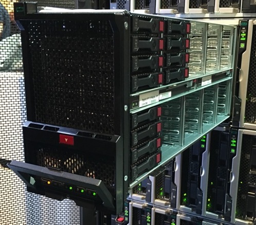
What is the mistake if the location of the disks seems to be correct, because according to the scheme, insert the first disk into bay 1, the second disk into bay 2, and so on?
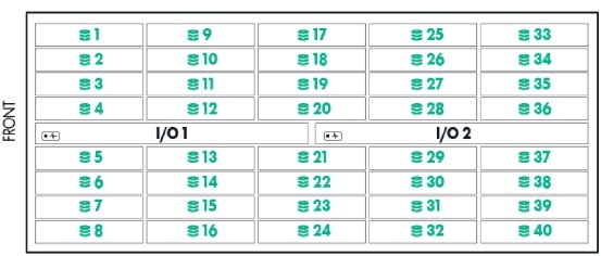
So yes not so. The HPE Synergy Configuration and Compatibility Guide has a completely different filling order: For proper air flow, drives must be populated from back to front. Per the drive numbering below, begin populating bays 33 through 40, and continue to populate back to front, finishing with bays 1 through 8. " In the figure, the arrows indicate a more correct location of the disks.
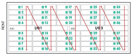
What is the reason for the illogical numbering is not clear. Now about the module. As already mentioned, it supports the installation of 40 pieces of SFF SAS or SATA drives. It is impossible (at least for now) to put in it an SFF module with two uFF disks, described in the second part of the “Chassis and Server”. I suspect that this function will never be realized, since the adapter box is 2 pcs. uFF -> SFF has a RAID adapter inside it that supports RAID levels 0 and 1, and the D3940 has no adapters at all, all disks from the module are presented to the HPE Smart Array P542D Controller with 2GB FBWC adapter installed in the server. The connection and power cables are placed in a flexible segmented sleeve, which is located at the bottom of the module, when pulling the module out of the chassis, the cables are unwound, during the reverse operation, they are unwound, this allows not to disconnect the module for maintenance (for replacing or adding disks, for example).
An example of a flexible segmented sleeve for a machine gun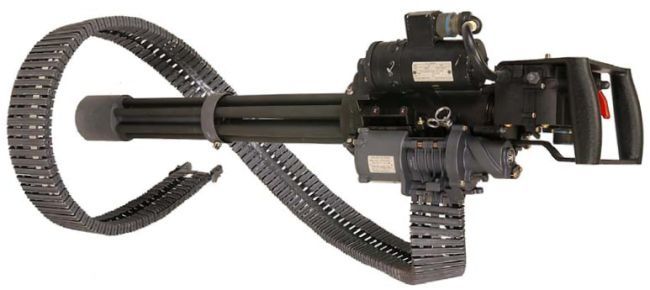

Disks are connected to SAS switches by SAS I / O modules, by default one piece is installed in the I / O 1 bay, which works with the HPE Synergy 12Gb SAS Connection Module SAS switch installed in the ICM 1 slot. If fault tolerance is required, in the bay I / O 2 installs a second I / O module, and a second SAS switch in the ICM 4 bay, in addition, each server that will work with D3940 disks needs to install the HPE Smart Array P542D controller in mezzanine slot 1. The module itself It looks boring, you can see it either in the photo in the first part (installed in ICM 1), or below:

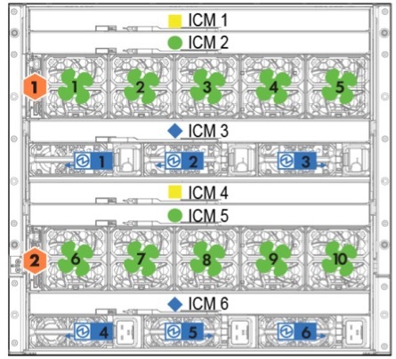
Just in case, once again the ICM (InterConnect modules) layout:
There is also a switching circuit of internal components, which explains why the connections occur this way and not otherwise (The storage module is only supported for connectivity with fabric 1):
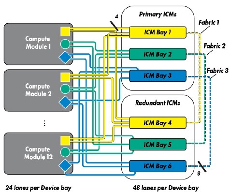
Compute module 1-12, meaning the server SY 480 Gen9 HH (Half Height), as I said, it has three compartments for installing mezzanine cards.
Thus, up to 10 half-size servers can be connected to one fully integrated D3940 disk module in the chassis, or vice versa - you can install five disk modules and two servers.
If you take a fault-tolerant configuration, the options will be as follows:
- SAS Connection Module in ICM 1 compartment connects to the main I / O adapters for compartments 1, 3 and 5;
- SAS Connection Module in ICM 4 compartment connects to the main I / O adapters of bays 7, 9 and 11;
It turns out that if there are more than three disk modules planned, then you will have to install both the second I / O modules and the second SAS switch. According to the documentation, for three or more full-size servers (FH - full height) and two disk modules, a second SAS switch is also required.
The SAS switch has 12 internal 4x12 Gbps SAS ports per link and creates a dynamic virtual JBOD that can connect to servers inside the chassis. Separately, it should be noted that Factory 1 is non-blocking, which allows you to fill up SSD disk modules and enjoy the colossal IOPs and minimal reading time. A SAS switch is controlled through Synergy Composer or a server with OneView version 3.0 or higher.
You cannot connect disk modules in one chassis to servers in another chassis, this is a very big sadness. Perhaps something will change.
Let's get back to the D3940 disk module. As already mentioned, you can install up to 40 SFF disks in a module and up to five modules in a chassis, for a total of 200 disks; inside the module, you can install any of the drives listed above, but we must remember that a logical array can only be created on drives of the same type. At the moment, the list of supported disks is as follows:
44 types of drives supported by the D3940
- HP 500GB 6G SATA 7.2k 2.5in SC MDL HDD
- HP 200GB 12G SAS ME 2.5in EM SC H2 SSD
- HP 400GB 12G SAS ME 2.5in EM SC H2 SSD
- HP 800GB 12G SAS ME 2.5in EM SC H2 SSD
- HP 1.6TB 12G SAS ME 2.5in EM SC H2 SSD
- HP 1.2TB 6G SAS 10K 2.5in DP ENT SC HDD
- HP 600GB 12G SAS 10K 2.5in SC ENT HDD
- HP 1.2TB 12G SAS 10K 2.5in SC ENT HDD
- HP 300GB 12G SAS 10K 2.5in SC ENT HDD
- HP 900GB 12G SAS 10K 2.5in SC ENT HDD
- HP 800GB 12G SAS VE 2.5in SC EV SSD
- HP 1.6TB 12G SAS VE 2.5in SC EV SSD
- HP 300GB 12G SAS 15K 2.5in SC ENT HDD
- HP 450GB 12G SAS 15K 2.5in SC ENT HDD
- HP 600GB 12G SAS 15K 2.5in SC ENT HDD
- HP 600GB 12G SAS 15K 2.5in SC 512e HDD
- HP 100GB 6G SATA ME 2.5in SC EM SSD
- HP 400GB 6G SATA ME 2.5in SC EM SSD
- HP 800GB 6G SATA ME 2.5in SC EM SSD
- HP 200GB 12G SAS WI 2.5in SC SSD
- HP 400GB 12G SAS WI 2.5in SC SSD
- HP 800GB 12G SAS WI 2.5in SC SSD
- HP 1.92TB 12G SAS RI 2.5in SC SSD
- HP 1TB 6G SATA 7.2k 2.5in 512e SC HDD
- HP 2TB 6G SATA 7.2k 2.5in 512e SC HDD
- HP 2TB 12G SAS 7.2K 2.5in 512e SC HDD
- HP 1TB 12G SAS 7.2K 2.5in 512e SC HDD
- HP 1.8TB 12G SAS 10K 2.5in SC 512e HDD
- HPE 480GB 12G SAS RI-3 SFF SC SSD
- HPE 960GB 12G SAS RI-3 SFF SC SSD
- HPE 1.92TB 12G SAS RI-3 SFF SC SSD
- HPE 3.84TB 12G SAS RI-3 SFF SC SSD - the largest drive
- HPE 400GB 12G SAS MU-3 SFF SC SSD
- HPE 800GB 12G SAS MU-3 SFF SC SSD
- HPE 1.6TB 12G SAS MU-3 SFF SC SSD
- HPE 3.2TB 12G SAS MU-3 SFF SC SSD
- HP 120GB 6G SATA VE 2.5in SC EV M1 SSD
- HP 240GB 6G SATA VE 2.5in SC EV M1 SSD
- HP 480GB 6G SATA VE 2.5in SC EV M1 SSD
- HP 800GB 6G SATA VE 2.5in SC EV M1 SSD
- HP 1TB 6G SATA 7.2k 2.5in SC MDL HDD
- HP 146GB 6G SAS 15K 2.5in SC ENT HDD
- HP 500GB 6G SAS 7.2K 2.5in SC MDL HDD
- HP 1TB 6G SAS 7.2K 2.5in SC MDL HDD
44 types of disks are supported, approximately 45% of the type of HDD, and approximately 55% of SSDs. At most one disk module can provide 153.6 TB (in the form of 40 pcs. HPE 3.84TB 12G SAS RI-3 SFF SC SSD in RAID0), or 768 TB - five modules (maximum) per chassis.
Separately, we should mention the HPE Smart Array P542D controller, which is installed in the server and manages the disks connected to it. It has a 2 GB DDR3-1866 MHz cache module, 16 12 Gbit / s SAS ports (2x4 internal, and 2x4 external) on board, but there are the following restrictions - 404 TB per logical disk and 64 logical disks per controller. On the host, the connected controller eats up 4.4 GB of memory. Supports RAID levels 0, 1, 10, 5, 50, 6, 60, 1 ADM, 10 ADM.
This controller has one option, purchased separately - HPE SmartCache - allows you to organize tiering of data (i.e. with frequent demand for data, it moves them to faster SSDs. It consists, respectively, of slow HDDs and fast SSDs connected to the controller, and meta-data about the demand for blocks of information from the array that are held in FBWC (Flash-backed write cache, flash write buffer, the same 2 GB DDR3 module). Personally, I have not tested this functionality, it would be interesting to see how the “temperature” levels of the data are set and how the controller copes with the “jitter” of this level.
All this magnificence is controlled by SY Composer, and on this review of this part will be considered complete.
At the end there was a description of the network part (the most difficult for me), control modules (the most incomprehensible) and the principles of construction and management (the most interesting).
