The game "Life" on the logic elements
I’ll warn you in advance: quite a few pictures.
This article will focus on the implementation of the game "Life" on the logical elements in the simulator "Atanua".
The game "Life" is perhaps one of the most recognizable cellular automata. Not one article has been written about her, including on Habrahabr . Once, too, became interested in her, but somehow for a long time was not enough.
Later I heard somewhere that modern computers have a speed limit caused by, among other things, the presence of a certain communication channel between the memory and the computing core. As a solution, it was proposed to collect a counting memory. I don’t remember exactly whether I myself remembered about Life, or whether it was mentioned in that article, but I wanted to model it in a logical circuit (to be precise, in a matrix of identical circuits). Why is it "Life"? The main reasons were its prevalence and fame, as well as the fact that the “universes” in it are Turing complete, which allows us to perform any calculations on it and solve various problems. It turns out, on the basis of this cellular automaton, you can create a computer. Atanua
simulator ( official site) was chosen as a tool), since it is quite easy to learn and displays the status of all lines. In the end, the following came out:
One convenient feature of the Atanua simulator is that you can connect circuits as a kind of microcircuit to other projects. I took advantage of this by collecting a matrix for debugging and experimentation.
For a more detailed look, the upper left corner:
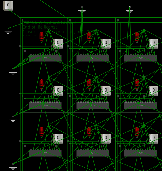
The “r” button is used to reset the circuit. Buttons signed as “0” are used to set the cell to a live state. I want to note, reset by pressing again is not yet implemented. The 3 lower groundings are used as circuit limiters so that a variety of artifacts do not appear. In Atanua, a wire can have 4 states:
Moreover, if an undefined state is applied to the input of a logic element, some may recognize it as 0, and some as 1. For this, limiters were set in the form of setting unused pins to 0.
Do not pay attention to the upper ground. The initial version of the circuit required initialization, for which this output was used. At present, it is a rudiment (so as not to redo the matrix), and its state can be any. Another wire that goes beyond the edge of the picture is the output of the clock signal. He goes to the set of generators on which he tested the maximum speed.
Now more about the cell layout. Due to problems with the quality of screenshots, I will give drawings of individual nodes.
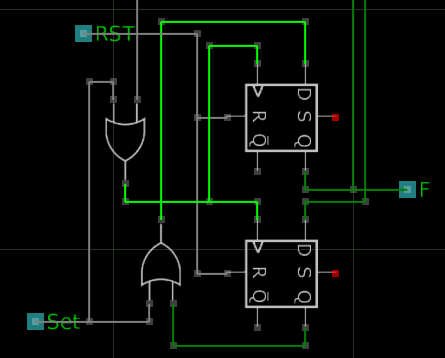
The figure above shows a 2-bit looped shift register on D triggers, which acts as a memory. There is one not good moment associated with it, which I still have to fix: during operation, the circuit seems to blink, because in the active state (when information is written in this register, that is, in the state of a living cell), the triggers are exchanged between 0 and 1 and it turns out that at the output F (output to display the status, to the LED for example) we have either 0 or 1 (this is noticeable in the video at the end of the article). RST is a reset input. SET - input setting the cell in the state of a living cell. As already mentioned, a single cell is not yet reset. On the top left is a clock signal. About the neighboring two wires below.
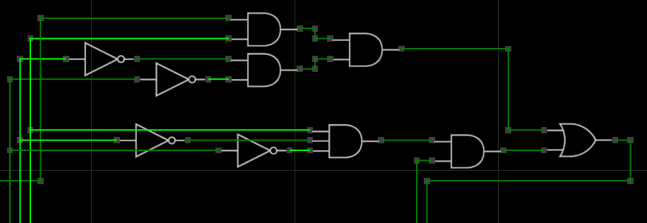
In the check block, a check is made for the condition of the game. Top for birth, bottom for survival. The peculiarity of this block is that it can be adjusted to other rules, thereby organizing similar cellular automata. The outputs from the adders are suitable on the left, on the bottom are the very two wires that go to the register. They, in fact, are connected in the context of one of the transfer lines of the register.
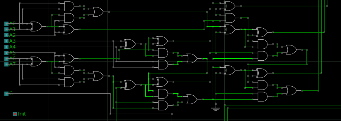
Perhaps the biggest and most controversial part of the circuit are parallel-series adders. Having implemented it, I solved the problem of checking the necessary conditions “on the forehead”, summing up all the inputs of A0-A7 from neighboring cells and checking the result for compliance with the conditions. In this case, the inputs A0 + A1 + A2, A5 + A6 + A7 are summed up first, then the outputs of the second sum, conclusions A3 and A4, and so on. In the end, it turned out in the end 6 adders and 1 half-adder. It is worth noting that one of the adders can also be replaced with a half adder, because one of its inputs is not used. Why I made one grounded input (dark green leaving the bottom of the picture below) - I don’t remember. Initially, I wanted to simplify it with the help of DNF or CNF, but there is no desire to solve the Carnot map 16x16 yet. So I don’t exclude the moment
C is an input of such a frequency; it has nothing to do with the adder circuit; it goes to the register. About Init I wrote above - a rudiment from the previous version.
I do not consider the game "Life" as a worthy cellular automaton for the implementation of counting memory, since the "program" for such a computer will take up a lot of space and is difficult to implement. But still, the circuit allows us to dream about a chip with the implementation of the cells of this game. I think it would be quite interesting to see the hardware implementation of this cellular automaton. And I mean not microcontrollers with the program, but exclusively on cells from logic elements.
As for the scheme, of course there are enough flaws in it, but enough for experiments. Will I modify it? Honestly, I do not know how the soul will lie.
Finally, a few videos with the work:
Glider:
Small ship:
Pentadecathlon also fit:
Project files on Google Drive.
Some explanation on the contents:
live.atanua - cell;
LiveFieldM.atanua - matrix;
LiveField.atanua - a small matrix element (8x8) from which LiveFieldM was created. The edges are not grounded.
To detect, put in one folder. If it does not help, edit the files in any text editor (by structure, regular XML).
This article will focus on the implementation of the game "Life" on the logical elements in the simulator "Atanua".
The game "Life" is perhaps one of the most recognizable cellular automata. Not one article has been written about her, including on Habrahabr . Once, too, became interested in her, but somehow for a long time was not enough.
Let me remind you what Life is:
There is a certain matrix of cells, which is called the "universe" (ideally infinite). At each iteration (called “days”), any cell can be “live” or “dead”, and its state depends on the previous iteration according to the following rules:
The neighborhood of a cell is the 8 surrounding cells (see Moore’s two-dimensional neighborhood of order 1 ).
More information about Life can be found on Wikipedia .
- A cell comes to life if there are 3 living cells in its vicinity.
- A cell continues to live if 2 or 3 cells are alive in its vicinity.
- In other cases, the cell dies.
The neighborhood of a cell is the 8 surrounding cells (see Moore’s two-dimensional neighborhood of order 1 ).
More information about Life can be found on Wikipedia .
Later I heard somewhere that modern computers have a speed limit caused by, among other things, the presence of a certain communication channel between the memory and the computing core. As a solution, it was proposed to collect a counting memory. I don’t remember exactly whether I myself remembered about Life, or whether it was mentioned in that article, but I wanted to model it in a logical circuit (to be precise, in a matrix of identical circuits). Why is it "Life"? The main reasons were its prevalence and fame, as well as the fact that the “universes” in it are Turing complete, which allows us to perform any calculations on it and solve various problems. It turns out, on the basis of this cellular automaton, you can create a computer. Atanua
simulator ( official site) was chosen as a tool), since it is quite easy to learn and displays the status of all lines. In the end, the following came out:
Single cell layout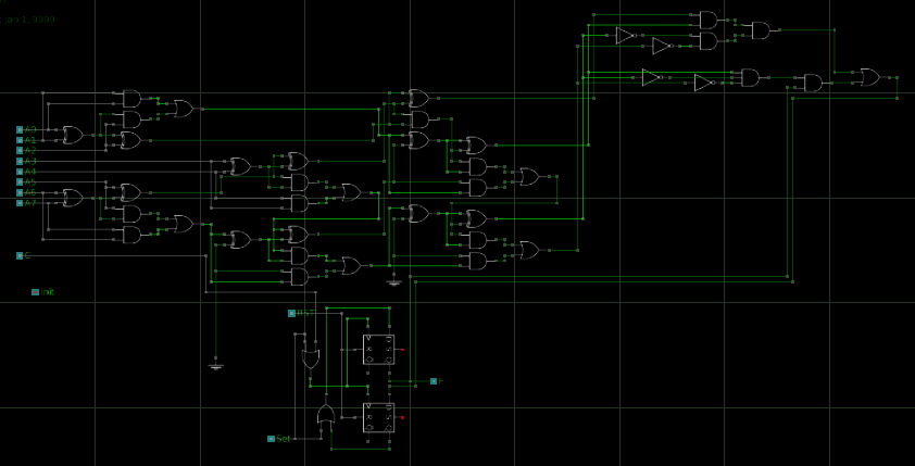
One convenient feature of the Atanua simulator is that you can connect circuits as a kind of microcircuit to other projects. I took advantage of this by collecting a matrix for debugging and experimentation.
Cell matrix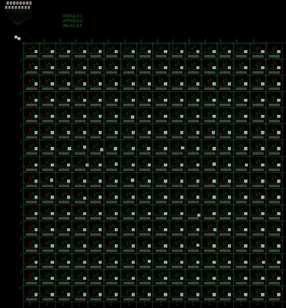
For a more detailed look, the upper left corner:
The “r” button is used to reset the circuit. Buttons signed as “0” are used to set the cell to a live state. I want to note, reset by pressing again is not yet implemented. The 3 lower groundings are used as circuit limiters so that a variety of artifacts do not appear. In Atanua, a wire can have 4 states:
- dark green: log. 0;
- light green: log. 1;
- red: not connected correctly;
- white: not connected (undefined state).
Moreover, if an undefined state is applied to the input of a logic element, some may recognize it as 0, and some as 1. For this, limiters were set in the form of setting unused pins to 0.
Do not pay attention to the upper ground. The initial version of the circuit required initialization, for which this output was used. At present, it is a rudiment (so as not to redo the matrix), and its state can be any. Another wire that goes beyond the edge of the picture is the output of the clock signal. He goes to the set of generators on which he tested the maximum speed.
Now more about the cell layout. Due to problems with the quality of screenshots, I will give drawings of individual nodes.
Register
The figure above shows a 2-bit looped shift register on D triggers, which acts as a memory. There is one not good moment associated with it, which I still have to fix: during operation, the circuit seems to blink, because in the active state (when information is written in this register, that is, in the state of a living cell), the triggers are exchanged between 0 and 1 and it turns out that at the output F (output to display the status, to the LED for example) we have either 0 or 1 (this is noticeable in the video at the end of the article). RST is a reset input. SET - input setting the cell in the state of a living cell. As already mentioned, a single cell is not yet reset. On the top left is a clock signal. About the neighboring two wires below.
Check block
In the check block, a check is made for the condition of the game. Top for birth, bottom for survival. The peculiarity of this block is that it can be adjusted to other rules, thereby organizing similar cellular automata. The outputs from the adders are suitable on the left, on the bottom are the very two wires that go to the register. They, in fact, are connected in the context of one of the transfer lines of the register.
Adders
Perhaps the biggest and most controversial part of the circuit are parallel-series adders. Having implemented it, I solved the problem of checking the necessary conditions “on the forehead”, summing up all the inputs of A0-A7 from neighboring cells and checking the result for compliance with the conditions. In this case, the inputs A0 + A1 + A2, A5 + A6 + A7 are summed up first, then the outputs of the second sum, conclusions A3 and A4, and so on. In the end, it turned out in the end 6 adders and 1 half-adder. It is worth noting that one of the adders can also be replaced with a half adder, because one of its inputs is not used. Why I made one grounded input (dark green leaving the bottom of the picture below) - I don’t remember. Initially, I wanted to simplify it with the help of DNF or CNF, but there is no desire to solve the Carnot map 16x16 yet. So I don’t exclude the moment
C is an input of such a frequency; it has nothing to do with the adder circuit; it goes to the register. About Init I wrote above - a rudiment from the previous version.
Total
I do not consider the game "Life" as a worthy cellular automaton for the implementation of counting memory, since the "program" for such a computer will take up a lot of space and is difficult to implement. But still, the circuit allows us to dream about a chip with the implementation of the cells of this game. I think it would be quite interesting to see the hardware implementation of this cellular automaton. And I mean not microcontrollers with the program, but exclusively on cells from logic elements.
As for the scheme, of course there are enough flaws in it, but enough for experiments. Will I modify it? Honestly, I do not know how the soul will lie.
Finally, a few videos with the work:
Glider:
Small ship:
Pentadecathlon also fit:
Project files on Google Drive.
Some explanation on the contents:
live.atanua - cell;
LiveFieldM.atanua - matrix;
LiveField.atanua - a small matrix element (8x8) from which LiveFieldM was created. The edges are not grounded.
To detect, put in one folder. If it does not help, edit the files in any text editor (by structure, regular XML).