September 22, 2015 at 11:50
Router Reservation Using VRRP
We launched a new service: reservation of a router using the VRRP protocol (it is known abroad as failover IP. As far as we know, no one has done anything like this in Russia before. The service will be of interest primarily to those who would like to ensure constant business availability. -znachimyh Internet resources, but does not possess sufficient for this technical possibilities: either has its own autonomous system, or IP-address block, audio connections to service providers on BGP protocol.
on the peculiarities of its technical assistance with second implementation, we describe in detail in this article.
Choose a reservation scheme
Imagine that we have a critically important Internet resource for business, which should always be available to a large number of users. This resource www.mysite.ru has an IP address 12.34.56.78 issued by the provider as part of block 12.34.56.72/29.
The network settings of the resource (address, mask, and default gateway) look like this:
ifconfig eth0 address 12.34.56.78 mask 255.255.255.248 gw 12.34.56.73
If .78 is the host address, then .73 is the default gateway address. This address is the operator’s area of responsibility, and if the host is located in the data center, then the data center’s area of responsibility. This diagram can be represented graphically as follows:
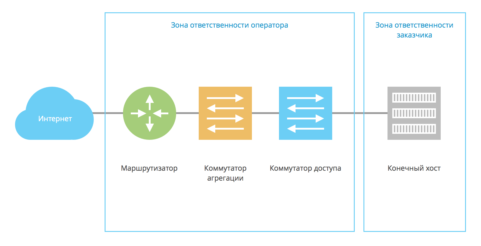
The address 12.34.56.78 is written on the final host, .73 on the router, and a single L2 domain is organized between them (usually a separate VLAN):
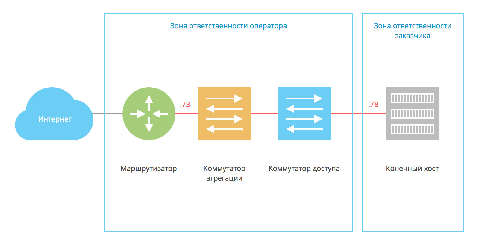
To increase the level of availability of the final host, network infrastructure redundancy is required .
For redundancy at the L2 level, in the simplest case, Virtual Chassis / Fabric / MC-LAG is used. Then the end host connects to the data center network using the LAG (Etherchannel):

Possible points of failure are the end host itself and the router.
Reservation of the end host is the responsibility of the customer. It is highly desirable that the final and backup hosts are located in different data centers. This will avoid many problems (with the network structure, with the availability of a specific physical server, with power supply and cooling at individual sites).
There are several ways to organize IP address transfer between the primary and backup hosts. Within one L2 segment, this can be done using CARP / HSRP / VRRP protocols and their analogues:

Full-fledged reservation at the data center level can only be discussed if if all service components are reserved and they do not have a single point of failure.
The ideal backup scheme can be represented as follows:
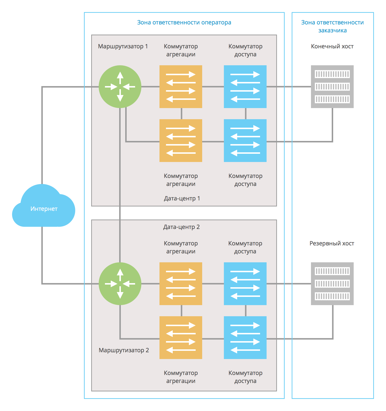
Final and backup customer hosts are located in different data centers. Operator-owned routers are also located in different data centers. Data centers can be connected by several communication channels.
If a malfunction occurs in one of the data centers, the end host will still be available. The described approach can be used for redundancy in both L2 and L3 schemes.
Router Reservation
An example of redundancy at the L3 level is anycast routing using BGP with a higher level operator. Each of the hosts announces a 12.34.56.72/29 network with different priorities on the telecom operator's routers. At the same time, each host connects to the routers of the telecom operator with a separate subnet, a separate VLAN:

This scheme has the following advantages:
- It is widely used on the Internet (BGP);
- scaling is carried out not on two, but on several data centers;
It is not without its drawbacks, among which are:
- low speed (by default, the convergence rate of BGP is from 1.5 minutes);
- difficulty setting
- the need to allocate separate subnets for connection in each data center.
The speed of switching to the backup host can be accelerated if you use not BGP, but another protocol - OSPF or IS-IS . The difficulty here lies in the fact that not every telecom operator will make it possible to use these protocols: they usually transmit service data (for example, MPLS tags or service addresses), and there are no full-fledged restrictions.
When using the L2 scheme, the operator organizes a single L2 domain between the primary and secondary hosts. A VXLAN or MPLS tunnel is organized between the routers:
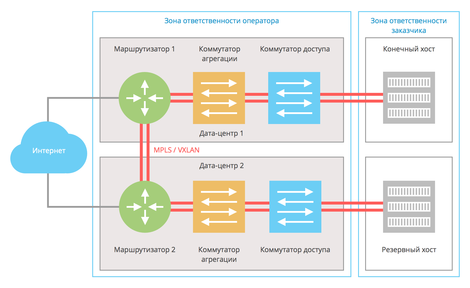
VXLAN / MPLS helps organize redundancy using several communication channels between the provider's routers.
The final and backup hosts use VRRP or its analogs among themselves. Thus, the IP address 12.34.56.78 appears on the currently active host (if both hosts are active, then on the configured master host). The final host receives the IP address from this network - 12.34.56.77, the backup host receives the address from the same network - 12.34.56.76. If Windows is installed on the hosts, then NLB clustering can be used instead of VRRP.

A similar scheme is built by the operator. Both routers participate in the same VRRP domain and share the default gateway address —12.34.56.73 / 29. Router 1 is a preconfigured wizard with a physical IP address of 12.34.56.73, and router 2 is a backup router with a physical address of 12.34.56.74; the address 12.34.56.73 for it is virtual and active only when router 1 is unavailable. The

undoubted advantages of this scheme are:
- use of standard protocols (VRRP);
- ease of setup, both on the part of the customer and the operator;
- high speed of work;
There is only one drawback: the scheme is inconvenient to scale to more than two data centers.
If a malfunction occurs: how it works
In a normal situation, both routers and both customer hosts work. One of the routers at the stage of constructing the scheme is assigned as the main one (master) and responds to the address 12.34.56.73. The situation is the same with the hosts: one of them is the main one and responds to requests to the address 12.34.56.78. The second router and the second host are standby.
Requests from the Internet go through router 1 and go to the primary end host. On routers, there is an ARP record of 12.34.56.78 with a MAC address of 0000: 5E00: 01xx, pointing towards the main host. The main host responds to hosts on the Internet by routing through router 1 (the default gateway 12.34.56.73 is specified for hosts). To reduce network latency, the main router is located in the same data center as the main host.
What happens when one of the hosts is unavailable? VRRP on the standby host determines that the main host has stopped responding to keep-alive requests, and the IP address 12.34.56.78 is set on the standby host:
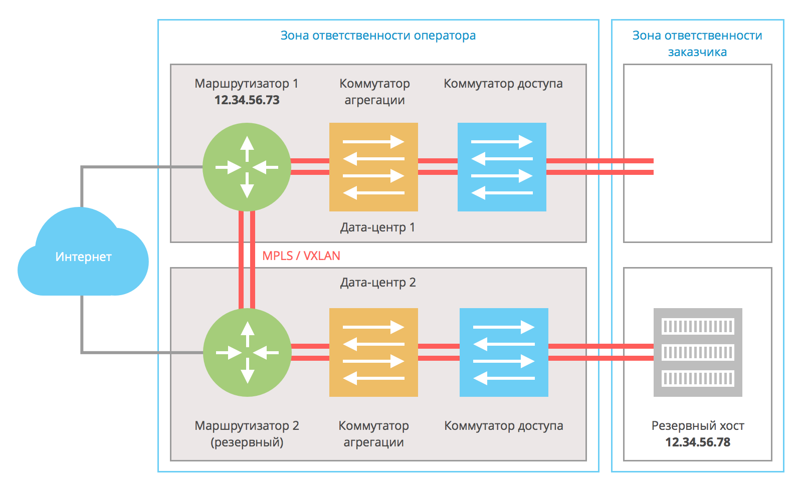
Internet polls get to router 1; he sees in his ARP table the MAC address corresponding to the IP address 12.34.56.78 from the side of router 2 and sends traffic to the backup host. The standby host sends response traffic to the default gateway 12.34.56.73, i.e. through router 1. Using this scheme, network latency between hosts on the Internet and the redundant host increases.
After troubleshooting, the IP address 12.34.56.78 is again available on the main host, and the circuit works as usual.
Similarly, this scheme works in the event of a network infrastructure failure between the router and the end host:
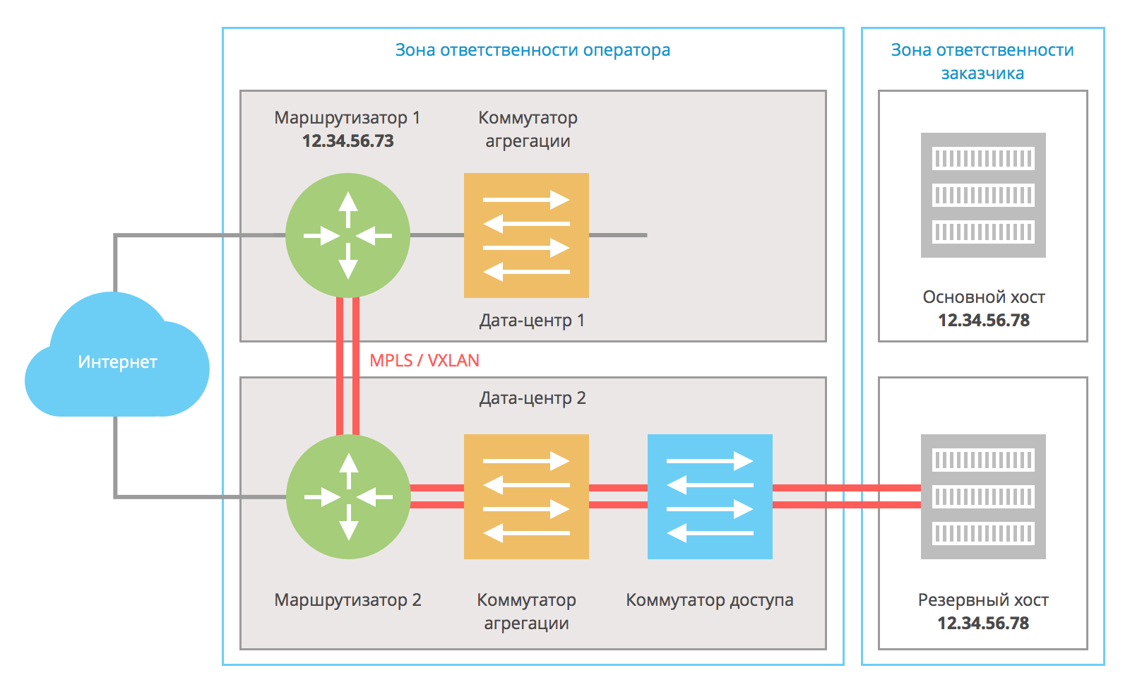
If the intermediate switch fails, the main host remains the carrier of address 12.34.56.78, but it does not have network communication with the router and is not involved in processing requests from The Internet. The backup host, having lost connectivity with the primary, becomes responsible for the address 12.34.56.78.
If router 1 or the entire data center 1 becomes completely inaccessible, then the scheme works exclusively through router 2 and the backup host:
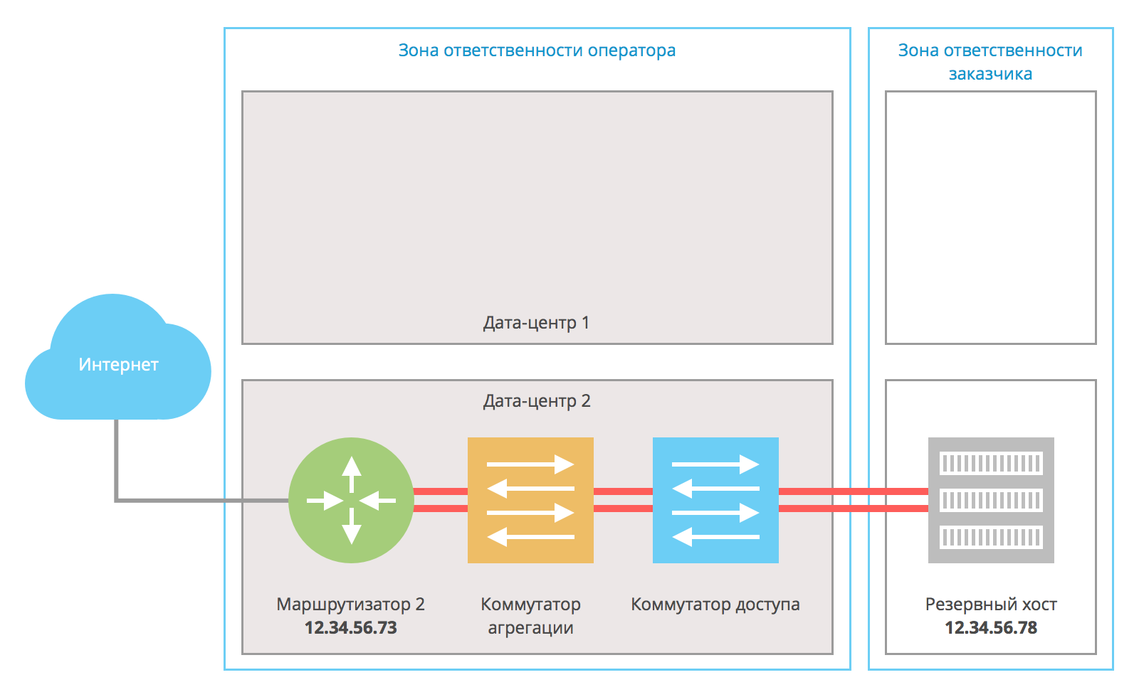
After restoring the infrastructure, the scheme goes into normal operation. Virtually no faults in data center 2 affect the availability of the end host.
This solution allows the installation and maintenance of highly available resources, their full reservation and distribution in separate data centers.
Conclusion
In this article, we looked at technology for backing up network connections using the VRRP protocol. The corresponding service can be ordered in our control panel .
If you have any questions, welcome to comment. Readers who for one reason or another cannot post comments here are welcome to join us on our blog .