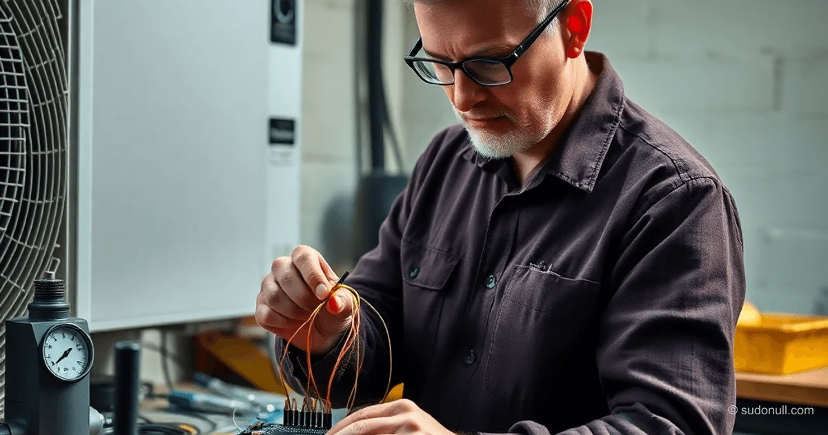
Arduino for Split-System Control: Building a Refrigeration Room
A split-system consists of an indoor and outdoor unit connected by copper tubes for refrigerant. The indoor unit is a fan with an evaporator and control board. The outdoor unit houses the compressor and fan. On/off models operate discretely: the compressor is either on or off. For installation, pre-made kits up to 5 m long with flared ends are used.
Installation requires:
- Tube cutter, flaring tool, tube bender (lever or spring type).
- Manifold gauge set, vacuum pump.
- Adapters for R410A ports (5/16" instead of 1/4").
The tubes (liquid line thin, gas line thick) are run through the wall with a slope for condensate. Connect with nuts without gaskets. Mandatory vacuuming removes air and moisture, preventing acid formation in the compressor oil. Process: connect the blue hose to the service port on the outdoor unit, evacuate for 30–60 minutes, check for leaks.
After vacuuming, open the refrigerant valves with a hex key, quickly disconnect the hose.
Electrical Connection Diagram
Unit contacts: 1 — compressor (220V), 2N — neutral, 3 — 4-way valve (cooling/heating mode), 4 — outdoor fan.
- Cooling: 1 + 4.
- Heating: 1 + 3 + 4.
The indoor unit handles logic but is limited to a minimum of 16°C. For +7°C, an external controller based on Arduino or ESP8266 is needed.
Arduino Controller: Basic Logic
Use DS18B20 to monitor room temperature and tube temperatures (inlet/outlet). Issue: after compressor shutdown, pressure in the liquid line rises faster, causing hydraulic shock on restart.
Solution:
- 3-minute delay between compressor off and on.
- Outdoor fan runs for 3 minutes after compressor stops.
- Separate relays: compressor (1), fan (4), valve (3).
Example pseudocode for ESP8266:
#include <OneWire.h>
#include <DallasTemperature.h>

OneWire oneWire(2);
DallasTemperature sensors(&oneWire);

void setup() {
  sensors.begin();
}

void loop() {
  sensors.requestTemperatures();
  float temp = sensors.getTempCByIndex(0);
  if (temp > 7.0 && !compressorOn) {
    // 3-minute delay
    delay(180000);
    digitalWrite(COMPRESSOR_PIN, HIGH);
    compressorOn = true;
  }
}
Add tube temperature checks to prevent startup if ΔT > threshold.
Resolving Power and IR Control Issues
During power dips, the indoor unit "sleeps," and the compressor runs without airflow. Solution — IR module (IR LED + IRremote library) to emulate remote commands: "turn on," "cooling mode," "temperature 16°C."
Logic:
- If loss of connection is detected (no airflow > 30 s) — send IR wake-up signal.
- Use ESP8266 with relays and IR.
Remotes use NEC protocol: capture codes from the original remote with an oscilloscope or library.
#include <IRremote.h>

IRsend irsend;

void wakeAC() {
  irsend.sendNEC(0x20DF10EF, 32); // Example power-on code
}
Scaling and Optimization
The system stably maintains +7°C. For senior developers: integrate MQTT for remote monitoring, PID controller instead of on/off to reduce compressor cycles. Add pressure sensors, compressor vibration sensors.
- Advantages: low cost, customization.
- Risks: warranty voided, requires soldering/flaring skills.
- Alternatives: Peltier modules (low efficiency), industrial chillers (expensive).
Key points:
- Vacuuming is mandatory for R410A — moisture damages the compressor.
- 3-minute delay prevents hydraulic shock.
- IR emulation solves network issues.
- Monitoring tube ΔT is critical for reliability.
- Use a tube bender — bending by hand flattens copper.
— Editorial Team










No comments yet.