Building an Autonomous Solar-Powered Outdoor Temperature Sensor: A Practical Guide
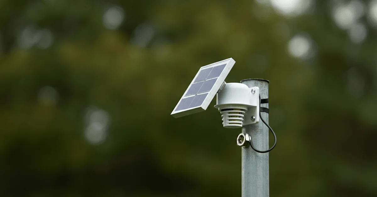
The development of autonomous wireless sensors capable of operating without external power and regular maintenance is of significant interest for IoT projects and monitoring systems. This article provides a detailed guide on building an outdoor wireless thermometer that self-powers using a solar panel. Special attention is given to addressing power supply challenges in low-light conditions, component selection, and consumption optimization to ensure long-term, reliable device operation.
Autonomous Power Supply Challenges and Solutions
The primary challenge in developing an autonomous sensor is ensuring stable power, especially under variable lighting conditions. For the outdoor thermometer developed in this project, the goal was to create a system capable of operating from solar energy, storing it, and expending it efficiently. We opted for a 90mm solar panel with a PET coating, providing UV resistance. While the stated specifications (4.5V, 100mA) are rarely achieved, real-world measurements of 80mA and an open-circuit voltage (EMF) of up to 5.5V in sunlight proved sufficient for basic charging.
Supercapacitors with a total capacity of 10F were chosen as the internal energy storage. Their advantages include a long service life and the ability to charge across a wide temperature range from -40 to +50 °C. Calculations showed that to ensure 24-hour operation without recharging, with an average circuit consumption of about 220 µA (at a measurement period of 256 seconds), a capacity of approximately 7.6F is required. Two 5F supercapacitors connected in parallel provide the necessary reserve. The maximum voltage across the supercapacitors is set at 5V to maximize stored energy.
A key problem was ensuring charging in cloudy weather, when the solar panel outputs only 2-3.5V and 0.1-1mA. In such conditions, standard boost converters (e.g., NCP1402SN50T1G, ZXSC310, MCP1640) can get stuck at their startup threshold voltage, drawing all available current without charging the supercapacitors. To solve this, an intelligent pre-charge accumulation system was developed, including capacitors C8-C11 and a hysteresis comparator built with transistors VT7-VT9 and a Zener diode VD6 (in this case, a green LED). This circuit allows the DA2 converter to start only when there is sufficient voltage on the accumulation capacitors, enabling 'burst' charging of the supercapacitors even with minimal energy generation from the solar panel. The comparator's lower trigger threshold is set at 1V, which is above the converter's 'stuck' threshold, preventing inefficient operation.
- Solar Panel: 90mm, PET-coated, up to 80mA.
- Energy Storage: 10F supercapacitors (2x5F in parallel), operating voltage up to 5V.
- Boost Converter: NCP1402SN50T1G.
- LDO Regulator: LP5907MFX-3.3.
- Smart Charging System: Hysteresis comparator for low-light conditions.
- Temperature Range: -40…+50 °C.
- Runtime without Recharge: ~30 hours.
Practical tests showed that the supercapacitors charge at a rate of 100-150 mV per hour even in the most inclement weather. During autumn and winter, they gain over 1V during daylight hours, and on typical days, they are fully charged by noon. Throughout operation, the voltage across the supercapacitors never dropped below 3.2V, confirming the effectiveness of the developed system.
Microcontroller and Sensors: Selection and Optimization
The PIC16F1825 microcontroller (MCU) was used, which was readily available, although a more energy-efficient PIC16LF1825 would have been preferable. However, the main power consumer in the system is the JDY-40 transceiver, which draws up to 40mA in transmit mode and 24mA in receive mode. To minimize power consumption, the transceiver is activated for only 2 seconds: 1 second for transmitting measured data (temperature, pressure, humidity) and 1 second for receiving settings (address, channel, power, measurement frequency). After this, the MCU enters sleep mode for 256 seconds, using a WDT timer for wake-up. The absence of acknowledgment and retransmission is a deliberate choice for power saving, although such functionality can be implemented if needed.
To ensure accurate UART data transmission across a wide temperature range, the microcontroller's clock generator is crystal-stabilized. The BME280 was chosen as the primary sensor, allowing for temperature, humidity, and atmospheric pressure measurements. Despite the BME280 not being an ideal solution for outdoor use due to its moisture sensitivity, its comprehensive functionality outweighed this drawback. Additionally, light intensity is measured in arbitrary units, and the MCU's built-in sensor provides temperature as a backup data source.
For further power consumption optimization, an energy-saving mode is implemented: if the voltage across the supercapacitors drops below 3V, the measurement and data transmission interval doubles to 512 seconds. The sensor board is built on a double-sided PCB measuring 100x23 mm, allowing for a compact arrangement of all components.
Sensor Construction and Protection for Outdoor Use
The mechanical design of the sensor, built using a 'sewer pipe technology' approach, provides essential protection against external influences and thermal insulation. It consists of four main elements:
- Outer Supporting Casing: A 63x25x63 polypropylene tee, which also acts as a thermal shield.
- Inner Casing: A 32mm sewer pipe coupling with end caps, housing the sensor board.
- Lid: A hand cream jar lid, onto which the solar panel is mounted.
- Mounting Pole with Holder: A 25mm polypropylene pipe section and a generic flag holder for mounting.
The solar panel is attached to the lid, and the connection to the sensor board is made with a two-core cable, tightly inserted into the lid to create a makeshift waterproof cable entry. Free air circulation is ensured between the outer and inner casings, and holes are made in the inner casing for ventilation around the BME280 sensor. For waterproofing, the PCB is coated with three layers of PLASTIK 71 lacquer. It is important to avoid getting lacquer into the small opening of the BME280 sensor.
This design demonstrates how, using readily available materials and well-thought-out engineering solutions, a reliable and durable autonomous sensor for environmental monitoring can be created. The project highlights the importance of a holistic approach to development, including power consumption optimization, selection of components resistant to external conditions, and adequate mechanical protection.
Key Takeaways
- Efficient Power Supply: A solar panel and supercapacitor system with intelligent charge management was developed, enabling operation even in low-light conditions and temperatures down to -40°C.
- Consumption Optimization: The use of an energy-efficient microcontroller, pulsed operation of the radio module, and a power-saving mode for low charge ensure extended autonomous operation.
- Sensor Selection: The BME280 is used for temperature, humidity, and pressure measurements, considering its outdoor application specifics, along with a backup sensor in the MCU.
- Robust Construction: Utilizing readily available materials and 'sewer pipe technology' to create a durable, sealed, and thermally insulated enclosure.
- Long-Term Operation: The system has demonstrated high reliability and stable performance, maintaining supercapacitor charge levels even in adverse weather conditions.
— Editorial Team










No comments yet.