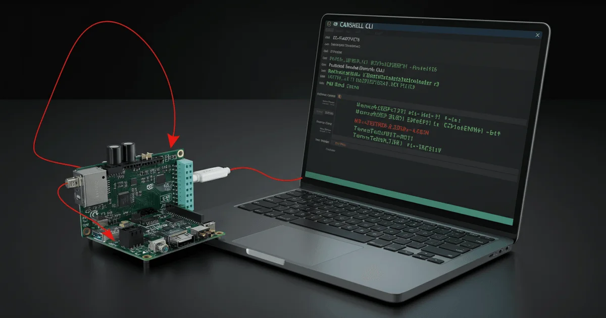
Embedded System Debugging: CLI over CAN with ISO-TP and CANshell
Developing embedded systems often presents challenges due to limited debugging interfaces. When traditional UART is unavailable but CAN buses are present, alternative methods for remote interaction become essential. This article describes an approach to implementing a Command Line Interface (CLI) over a CAN bus using the ISO-TP protocol and a specialized CANshell utility, providing a comprehensive debugging environment for microcontrollers.
The Challenge of Debugging Without UART
Classic embedded system debugging traditionally relies on serial interfaces like UART. However, in real-world projects, especially when developing specialized electronic boards, UART might be absent or reserved for other purposes. In such scenarios, with multiple CAN ports available, the task arises to utilize the CAN bus for transmitting debug information and control commands.
The primary complexities involved are:
- Limited CAN Packet Size: A standard CAN packet holds only 8 bytes of data. This is severely insufficient for transmitting long CLI commands, which can reach 150 bytes or more, as well as for receiving voluminous responses and logs. Solving this problem requires a protocol capable of fragmenting and reassembling data from multiple CAN packets.
- Data Stream Separation: Remote debugging often requires simultaneous interaction with the debugger's own CLI and the remote device's (ECU) CLI. It's crucial to efficiently separate and display these streams on a single terminal.
- Log Redirection: Embedded firmware typically outputs logs to UART or SWO. To use CLI over CAN, a mechanism is needed to redirect these logs to the chosen CAN interface via ISO-TP.
To address these challenges, we propose using the ISO-TP (ISO 15765-2) protocol, which allows transmitting messages of arbitrary length over a CAN bus, and developing a specialized console utility, CANshell, for the PC.
Solution Architecture: ISO-TP and CANshell
The proposed solution is based on the combination of the ISO-TP protocol and the CANshell utility. ISO-TP ensures reliable transmission of large data volumes over CAN, while CANshell acts as a bridge between a TCP client (e.g., PuTTY or TeraTerm) and the CAN bus.
Operational Principle:
- On the PC Side: The CANshell utility starts a TCP server and opens a TCP socket. This socket is connected on one side to the ISO-TP protocol and on the other to the TCP client. Connection parameters (ISO-TP addresses, COM port, CAN speed) are passed to the utility via command-line arguments, allowing for automation through scripts.
- On the Microcontroller (ECU) Side: An ISO-TP stack is implemented, which receives data from the CAN bus and passes it to the CLI command parser. For outputting logs and responses, a redirection mechanism is used, allowing this data to be sent back via ISO-TP.
- Interaction: When the TCP client sends a command, CANshell intercepts it, encapsulates it into ISO-TP packets, and sends it via a USB-CAN converter to the CAN bus. On the microcontroller, the ISO-TP stack reassembles the packets, and the command is fed to the CLI parser. Responses and logs from the microcontroller are similarly encapsulated into ISO-TP, transmitted via the CAN bus to CANshell, and then to the TCP client.
Component Implementation and Code Examples
For practical implementation, the USB2CANFD_V1 USB-CAN converter was chosen due to its availability and ease of interaction via a serial COM port using the SLCAN protocol. The JZ-F407VET6 development board, with its two CAN ports, was used as the target platform.
The TCP server on the PC side is implemented in pure C using WinSock2 functions. This allows maximum reuse of ISO-TP protocol components and FIFO queues in both the microcontroller firmware and the PC application.
Receiving data on the microcontroller via ISO-TP and passing it to the CLI parser looks like this:
void iso_tp1_rx_done(n_indn_t* in_done){
    LOG_DEBUG(ISO_TP,"ISO_TP1,%s",Iso15765_n_indn_ToStr(in_done));
    if(N_OK==in_done->rslt){
#ifdef HAS_CLI
        IsoTpHandle_t* Node=IsoTpGetNode(1);
        if(Node) {
            Node->target_id = in_done->n_ai.n_sa;
            cli_process_data(Node->cli_num, in_done->msg, in_done->msg_sz);
            memset(in_done->msg,0,I15765_MSG_SIZE);
        }
#endif
    }
}
This iso_tp1_rx_done callback is invoked upon completion of receiving a full ISO-TP message. It extracts the data and passes it to the cli_process_data function for processing.
To redirect logs from the microcontroller to ISO-TP, a special command tpw 1 is used. After executing it, all logging functions (LOG_ERROR, LOG_INFO, LOG_DEBUG) begin writing data to the TxFIFO queue associated with the first ISO-TP instance.
void iso_tp1_puts(void* stream_ptr, const char* str, int32_t len) {
    IsoTpHandle_t* Node = IsoTpGetNode(1);
    if(Node) {
        if(str) {
            if(len) {
                bool res = fifo_push_array(&Node->TxFifo, (uint8_t*)str, (uint32_t)len);
                if(!res) {
                    Node->error_cnt++;
                }
            }
        }
    }
}

void iso_tp1_putc(void* stream_ptr, char ch) {
    IsoTpHandle_t* Node = IsoTpGetNode(1);
    if(Node) {
        bool res = fifo_push(&Node->TxFifo, (uint8_t)ch);
        if(!res) {
            Node->error_cnt++;
        }
    }
}
The iso_tp1_puts and iso_tp1_putc functions place characters or strings into the TxFifo buffer, from where they will be sent via ISO-TP.
Data Transmission Control and Synchronization
The IsoTpTx task on the microcontroller is responsible for extracting data from TxFifo and sending it via ISO-TP as the protocol state machine becomes ready.
static bool iso15765_tx_next(IsoTpHandle_t* const Node) {
    bool res = false;
    res = iso15765_is_idle( &Node->instance);
    if(  res) {
        uint32_t count = fifo_get_count(&Node->TxFifo);
        if(0 < count) {
            uint32_t txLen = 0;
            n_req_t isoTpFrame={0};
            isoTpFrame.fr_fmt=CBUS_FR_FRM_STD;
            res = iso_tp_node_to_address_info( Node, &isoTpFrame.n_ai);
            res = iso_tp_node_to_proto_ctrl_info(  Node, &isoTpFrame.n_pci);
            res = fifo_pull_array(&Node->TxFifo, isoTpFrame.msg, sizeof(isoTpFrame.msg), &txLen);
            if(res) {
                isoTpFrame.msg_sz = txLen;
                n_rslt ret = iso15765_send(&Node->instance, &isoTpFrame);
                res = iso15765_ret_to_res(ret);
            }
        }
    }
    return res;
}

bool iso_tp_tx_proc_one(uint8_t num) {
    bool res = false;
    IsoTpHandle_t* Node = IsoTpGetNode(num);
    if(Node) {
        LOG_PARN(ISO_TP, "IsoTp%u,ProcTx", num);
        res = iso15765_tx_next(Node);
        Node->spin++;
    }
    return res;
}
These code snippets illustrate the data transmission logic. The iso15765_tx_next function checks if the ISO-TP transceiver is idle, and if so, it extracts data from TxFifo and initiates transmission.
On the PC side, in the CANshell utility, data received via ISO-TP is also placed into a queue, from which it is then sent to the TCP client.
bool can_shell_iso_tp_rx_data(uint8_t num,
                              uint8_t iso_num,
                              const  uint8_t* const data,
                              uint16_t msg_sz) {
    bool res = false;
    if(data) {
        if(msg_sz) {
            SocketHandle_t * Socket = SocketGetNode(1);
            if(Socket) {
                res = fifo_push_array(&Socket->TxFifo, data, (uint32_t) msg_sz);
                log_debug_res(CAN_SHELL, res, "SocketTxFiFoPush");
            }
        }
    }
    return res;
}

static bool iso_tp_rx_done(uint8_t iso_num, n_indn_t* in_done) {
    bool res = false;
    if(in_done) {
        LOG_INFO(ISO_TP, "ISO_TP_%u,MoveDone:%s", iso_num, Iso15765_n_indn_ToStr(in_done));
        res = iso15765_ret_to_res(in_done->rslt);
        if(res) {
            IsoTpHandle_t *Node = IsoTpGetNode(iso_num);
            if(Node) {
                Node->target_id = in_done->n_ai.n_sa;
                Node->rx_done = true;
#ifdef HAS_CAN_SHELL
                res = can_shell_iso_tp_rx_data(1, iso_num, in_done->msg, in_done->msg_sz);
#endif
            }
        }else{
            LOG_ERROR(ISO_TP, "MoveErr,Ret,%u=%s", in_done->rslt,
                      Iso15765retToStr(in_done->rslt));
        }
    }
    return res;
}
These functions are responsible for receiving ISO-TP data on the PC side and transferring it to the buffer designated for the TCP socket.
The final stage involves transmitting data from the TCP server to the connected TCP client (PuTTY, TeraTerm):
static bool socket_server_connected_tx_proc(SocketHandle_t *const Node) {
    bool res = false;
    uint32_t tx_len = fifo_get_count(&Node->TxFifo );
    if(tx_len) {
        uint8_t TxPart[150] = {0};
        uint32_t tx_size = 0 ;
        res= fifo_pull_array(&Node->TxFifo , TxPart, sizeof(TxPart), &tx_size);
        if(res) {
            int tx_done_cnt = send(Node->socket_remote, (char*) TxPart, (int) tx_size, 0 );
            if(tx_done_cnt==tx_size) {
                res = true;
            } else {
                res = false ;
                int ret = 0;
                ret = WSAGetLastError();
                LOG_ERROR(LG_SOCKET_SERVER,
                          "SendFailedWithErrorCode,ErrCode:%d=%s",
                          ret, WSAErrorToStr(ret));
            }
        }
    }
    return res;
}
This code demonstrates how data from the socket buffer is sent to the client using the send function from WinSock2.
An important aspect is the synchronization of ISO-TP sessions. Situations were observed where CANshell became overwhelmed by the data flow, leading to message loss. The solution involved staggering ISO-TP sessions in time to allow both protocol instances to reset and process data successfully.
Using the CANshell Utility
To launch the CANshell utility, a series of positional arguments must be specified:
- COM Port: The number of the COM port to which the USB-CAN converter is connected (e.g.,
COM3). - CAN Bit Rate: The CAN bus speed in kbit/s (e.g.,
500000for 500 kbit/s). - PC's ISO-TP Address: The CANshell utility's own ISO-TP address on the network (e.g.,
0xC). - Target Device's ISO-TP Address: The ISO-TP address of the microcontroller (ECU) with which communication is to be established (e.g.,
0xA). - TCP Port: The TCP port number that CANshell will open for client connections (e.g.,
50003).
Example of launching the utility:
CANshell.exe COM3 500000 0xC 0xA 50003After launch, the CANshell utility will open two terminals: one for its own CLI, and another for the remote device's CLI, which can be accessed via a TCP client (PuTTY/TeraTerm) using the specified TCP port. This provides the debugger with full access to the remote system, simulating a direct UART connection.
Key Takeaways
- Addressing the Lack of UART: The proposed method enables a full-fledged CLI for debugging embedded systems, even when traditional UART is absent on the board, by utilizing available CAN buses.
- Leveraging ISO-TP for Large Data Transfers: The ISO-TP protocol is critically important for transmitting CLI commands and logs, as it overcomes the 8-byte CAN packet limitation by fragmenting and reassembling messages.
- CANshell Utility as a Bridge: The specialized CANshell utility on the PC acts as an efficient intermediary between standard TCP clients (PuTTY, TeraTerm) and the CAN bus, ensuring transparent data transfer.
- Bidirectional Communication and Logging: The system supports both sending commands to the ECU and receiving asynchronous logs and responses, with the ability to redirect logs directly to ISO-TP.
- Versatility and Scalability: The approach is based on standard protocols and widely available hardware, making it applicable to a broad range of embedded projects.
— Editorial Team










No comments yet.