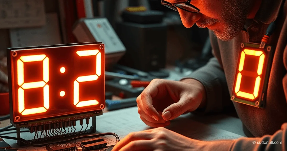
Desktop Clock with IV-11 VFD Tubes on STM32F401 and DC-DC Converters
This project builds a stylish desktop clock using vacuum fluorescent display (VFD) tubes—specifically the IV-11. The STM32F401CC microcontroller handles dynamic time display via an 8-channel driver like the TD62783AP (or compatible KID65783AP). Power comes from modern DC-DC modules: XL6009 boosts to 45V for the anode, while MP2307 steps down USB 5V to a precise 1.5V filament supply. The onboard hardware RTC keeps perfect time without any external modules.
IV-11 requirements: 1.5V filament, ~50V anode. Designed in Altium Designer with production-ready Gerber files.
Components and Schematic
Key parts:
- Microcontroller: STM32F401CC (Black Pill board) with built-in RTC.
- Display Driver: TD62783AP for high-voltage segment control.
- Power Supply:
- XL6009: Boost converter 5V → 45V.
- MP2307: Buck regulator for stable 1.5V filament.
- Display: 4-digit IV-11 VFD with dynamic multiplexing.
- Controls: Single button for time setting (short press: minutes; long press: hours).
Schematic uses GPIO for segments and digits, plus a timer for button debouncing.
Firmware in STM32CubeIDE
Code leverages a segment_lcd library for smooth dynamic display. Main loop: polls RTC, handles buttons, formats time string with blinking colon (2s period), and updates the display.
Full code:
#include "main.h"
#include "segment_lcd.h"
#include "stdio.h"
#include "button.h"

/* Private variables ---------------------------------------------------------*/
RTC_HandleTypeDef hrtc;
TIM_HandleTypeDef htim3;
TIM_HandleTypeDef htim10;

RTC_TimeTypeDef sTime = {0};
RTC_DateTypeDef DateToUpdate = {0};

/* Private function prototypes -----------------------------------------------*/
void SystemClock_Config(void);
static void MX_GPIO_Init(void);
static void MX_RTC_Init(void);
static void MX_TIM10_Init(void);

int main(void)
{
  HAL_Init();
  SystemClock_Config();

  MX_GPIO_Init();
  MX_RTC_Init();
  MX_TIM10_Init();

  HAL_PWR_EnableBkUpAccess();

  HAL_RTC_GetTime(&hrtc, &sTime, RTC_FORMAT_BIN);
  HAL_TIM_Base_Start_IT(&htim10);

  while (1)
  {
    HAL_RTC_GetTime(&hrtc, &sTime, RTC_FORMAT_BIN);
    HAL_RTC_GetDate(&hrtc, &DateToUpdate, RTC_FORMAT_BIN);

    BUTTON_Process();
    if (BUTTON_GetAction(BUTTON_SETTINGS) == BUTTON_SHORT_PRESS)
    {
      sTime.Minutes++;
      sTime.Seconds = 0;
      if(sTime.Minutes >=60)
      {
        sTime.Seconds = 0;
        sTime.Minutes = 0;
      }
      HAL_RTC_SetTime(&hrtc, &sTime, RTC_FORMAT_BIN);
    }

    if (BUTTON_GetAction(BUTTON_SETTINGS) == BUTTON_LONG_PRESS)
    {
      sTime.Hours++;
      if(sTime.Hours >=24)
      {
        sTime.Hours = 0;
      }
      HAL_RTC_SetTime(&hrtc, &sTime, RTC_FORMAT_BIN);
    }
    BUTTON_ResetActions();

    SEG_LCD_Process();
    HAL_Delay(1);

    char str[DIGITS_NUM + 2];
    if(sTime.Seconds % 2 == 0)
    {
      snprintf(str, DIGITS_NUM +2, "%02d.%02d", sTime.Hours, sTime.Minutes );
    }
    else
    {
      snprintf(str, DIGITS_NUM +2, "%02d%02d", sTime.Hours, sTime.Minutes );
    }
    SEG_LCD_WriteString(str);
  }
}

// ... (other functions: SystemClock_Config, MX_RTC_Init, MX_TIM10_Init, MX_GPIO_Init - see original)
Clock Setup and RTC Configuration
System clock: HSE 25 MHz → PLL 84 MHz (HCLK). LSE 32.768 kHz for RTC. Prescalers: async 127, sync 255. RTC calibration: smooth cal with -142 pulse correction over 32s.
First boot init: sets 12:00 on 02/12/2026, backup flag in BKP_DR0 (0x32F2). TIM10 (10 kHz) handles button processing.
GPIO: PB3-6,12-15 for digits/segments (push-pull output, low speed); PA2 for button (input, no pull).
Assembly and Debugging
- Send Gerbers to fab.
- Flash via STM32CubeIDE (ST-Link).
- Plug in USB 5V.
- Set time with button.
Tips: Skip fake TD62783AP—go with KID65783AP. For IV-6 tubes, add a resistor to drop filament to 1.2V.
Key Highlights
- TD62783AP dynamic drive saves GPIO pins.
- Built-in STM32 RTC—no need for DS3231.
- XL6009/MP2307 modules deliver rock-solid USB power.
- RTC calibration hits ±142 pulses/32s accuracy.
- Code compiles out-of-box; segment_lcd library simplifies VFD control.
— Editorial Team










No comments yet.