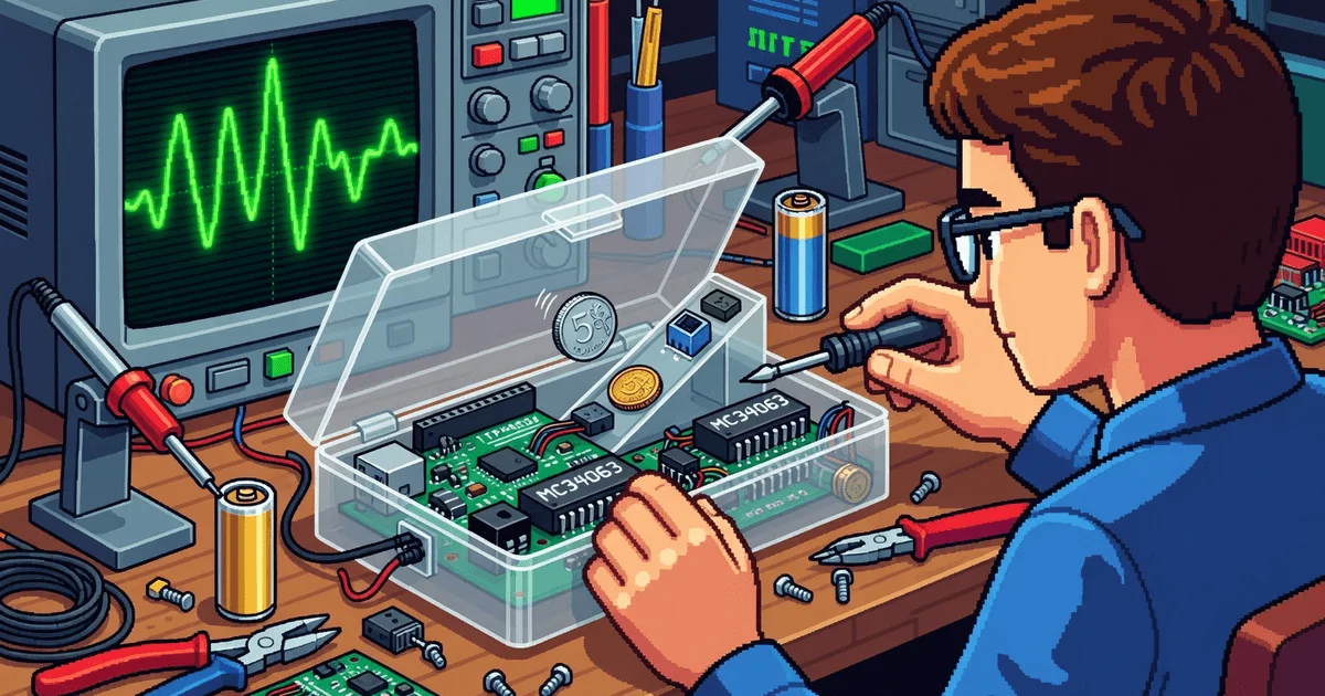
Arduino Coin Sorter with Optical Recognition, Custom PCB, and Power Optimization
The device identifies coin denominations by measuring the time it takes for a coin to pass through an optical gate. An infrared LED and phototransistor detect voltage drops as the beam is interrupted. Smaller coins like the 1-ruble produce a minimal signal due to their size, while larger 5-ruble coins create the strongest signal. The system captures the voltage-time curve and matches it against reference templates stored in the Arduino's EEPROM. It tallies coins by denomination and displays the totals on an LCD screen.
Li-ion Charging and Protection Circuitry
The 18650 battery charger uses the TP4056 to regulate current up to 1A and charge to 4.2V. Protection is handled by the DW01A chip, which monitors for deep discharge below 2.4V, overcharge above 4.3V, and short circuits. The FS8205A dual MOSFET disconnects the circuit on protection signals, requiring a charger connection to reset. Status LEDs show red during charging and green when complete.
Power Stabilization and Battery Life Trade-offs
A boost DC-DC converter based on the MC34063 steps up the battery's 3–4.2V to 5V for the Arduino Nano and display. Early prototypes shut down at 3.9V, but the new design runs down to 3V. However, current draw increased:
- Active mode: 124 mA
- Sleep mode: 4 mA (0.07 mA Arduino + 3.93 mA DC-DC)
A 2000–3000 mAh battery lasts about 20 days. For better efficiency, switch to the low-quiescent MT3608. Alternative: Run Arduino directly from the battery with BOD at 2.7V and enable DC-DC via transistor—potentially lasting up to a year.
Suppressing Noise from the Switching Regulator
The MC34063 generates noise that triggers false detections. A through-hole 470 µF electrolytic capacitor fixed it in prototypes. The custom PCB needed a full solution:
- LC filter with 2.3 kHz cutoff.
- Separating the DC-DC from analog sections and MCU.
- Dedicated grounds: analog and power.
Result: Ripple dropped from 111 mV to 13 mV, 18.6 dB attenuation (8.5x voltage reduction).
PCB Design and Fabrication
Schematic laid out in Altium Designer. The PCB was made using the photoresist method by hand. UV-exposed solder mask protects traces and adds polish. Components like the battery, IR sensor, button, and display use PLS connectors for compactness and easy swaps without resoldering.
Enclosure and Mechanics
3D model in SolidWorks, printed in ABS. Mounting uses M3 screws with embedded nuts for the display and battery compartment; clips secure the PCB. A partition isolates electronics from coins. The rear cover slides on rails for easy access. Charging port and LEDs are on the edge.
Key Takeaways
- Optical differentiation by diameter: Flight curve matched to references.
- Li-ion protection: TP4056 + DW01A + FS8205A with full cutoff on faults.
- DC-DC dominates sleep current (97%), needs redesign for longevity.
- Noise suppression: LC filter + layout + split GND cuts noise 8.5x.
- Modularity: PLS connectors simplify assembly and repairs.
Development Lessons
The project evolved from breadboard to custom PCB and 3D-printed enclosure. Key lesson: Plan power budget from day one. BOD tweaks and conditional DC-DC activation dramatically extend battery life. Reliability comes from smart layout and filtering—without them, false triggers are inevitable.
— Editorial Team










No comments yet.