Design and Assembly of a Joule Thief Blocking Oscillator for Low-Voltage Power
The Joule Thief blocking oscillator converts the low voltage from a depleted battery (0.3–0.6 V) into pulses to power an LED. The operating cycle consists of five stages: the transistor opens via the base resistor Rb, a linear current increase in the collector winding W1 with energy stored in the ferrite core, core saturation, the abrupt closing of transistor Q1, and the generation of a high-voltage pulse in the output winding W3 to illuminate the LED.
The cycle frequency is approximately 20 kHz, providing continuous visible light. The circuit minimizes power consumption and is suitable for navigation lighting with an LED current of 5–20 mA.
Circuit and Components
Classic topology: transistor Q1 (BC547C or KT3102), resistor Rb, a three-winding transformer on a ferrite ring (10×6×4 mm or 14×9×5 mm).
Advantages:
- Minimal number of components
- Reliable startup at 0.6 V
- Adjustable output voltage
- No audible noise at f > 17 kHz
Experimental Determination of Ferrite Parameters
Real ferrite characteristics differ from datasheet values. For calculation, wind a bifilar test coil (15 turns with a center tap).
Cross-sectional area Se = (D - d) × h / 2. For a 10×6×4 mm ring: Se = (0.01 - 0.006) × 0.004 / 2 = 8×10^{-6} m².
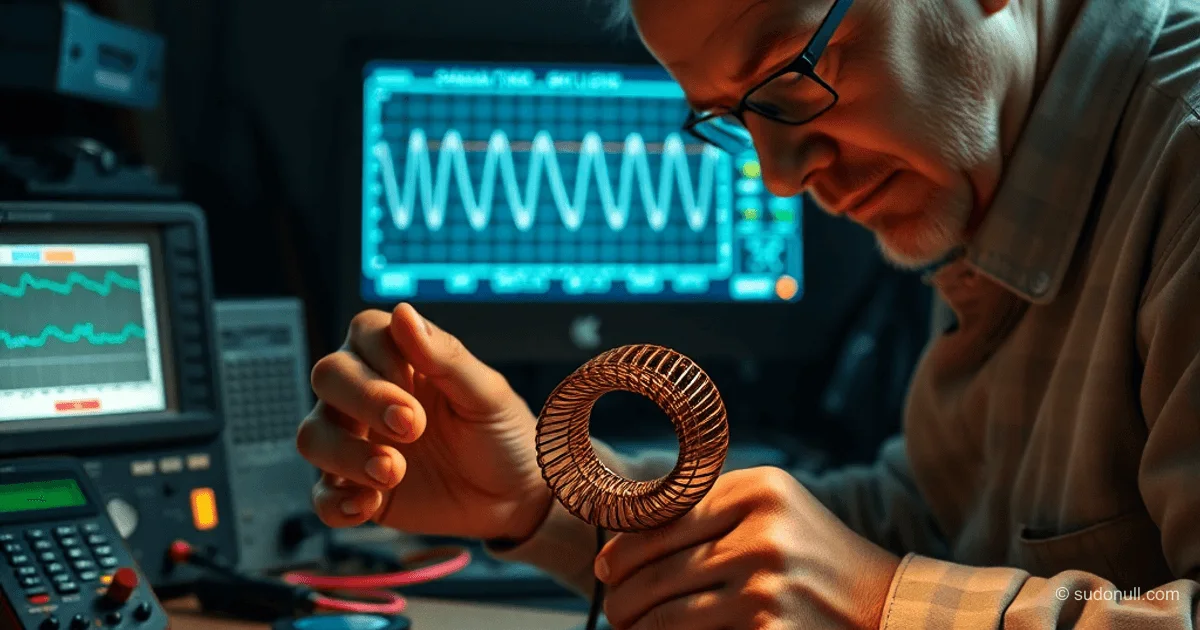
Saturation is determined using a test bench with a symmetrical multivibrator. On the shunt current oscillogram, note the curve inflection—a sharp slope increase as inductance drops.
Saturation induction Bsat = (U × T) / (2 × w × Se).
Example:
- U = 1.28 V
- T = 39.8 µs
- w = 15
- Se = 8×10^{-6} m²
Bsat = (1.28 × 3.98×10^{-5}) / (2 × 15 × 8×10^{-6}) ≈ 0.106 T.
Calculating Base Resistor Rb
Initial data:
- Uin = 1.5 V
- U_LED = 3.15 V (with 5% drop)
- I_LED = 10 mA
- Efficiency η = 70%
Pout = 3.15 × 0.01 = 0.0315 W
Pin = 0.0315 / 0.7 ≈ 0.045 W
Iavg = 0.045 / 1.5 = 0.03 A
Icpk = 2 × 0.03 = 0.06 A
Ib = (Icpk / h21e) × s, where h21e = 584 (measured with an RLC meter), s = 2.
Ib ≈ (0.06 / 584) × 2 ≈ 0.205 mA
Rb = (1.5 - 0.7) / 0.000205 ≈ 3.9 kΩ.
Frequency dependence on Rb:
| Rb | f |
|-------|-------|
| 1 kΩ | 16 kHz|
| 3 kΩ | 20 kHz|
| 6 kΩ | 24 kHz|
Optimal is 18–25 kHz to avoid audible whine.
Selecting Frequency and On-Time
Target f = 22 kHz. Duty cycle D = 40% from collector oscillogram.
ton = D / f = 0.4 / 22000 ≈ 18 µs.
Calculating Transformer Turns
N1 = (Uin × ton) / (Bsat × Se) = (1.5 × 1.8×10^{-5}) / (0.106 × 8×10^{-6}) ≈ 32 turns.
Base winding N2 = 1.2–1.5 × N1 for easy startup at low Uin. Chosen 1.5: N2 = 48 turns.
N2/N1 ratios:
- 0.5: poor startup
- 1.0: normal
- 1.2: good
- 1.5: very easy
- 2.0: base overload
Wind bifilar with wires. Output N3 = N1 × (Vout / Vpulse), where Vpulse is from collector oscillogram.
Assembly and Testing
After winding, test startup at 0.6 V, frequency, and LED current. Adjust turns by 10–20% for ferrite variations. The finished converter powers an LED from AA/AAA batteries until fully discharged.
Key Points
- Experimentally determine Bsat: ferrite datasheet data is unreliable.
- Choose Rb for f 18–25 kHz to avoid noise and losses.
- N2/N1 ratio = 1.5 ensures startup at 0.4–0.6 V.
- Test on a real bench with an oscilloscope for accuracy.
- 70% efficiency is achieved at I_LED 5–20 mA with proper transistor selection.
— Editorial Team










No comments yet.