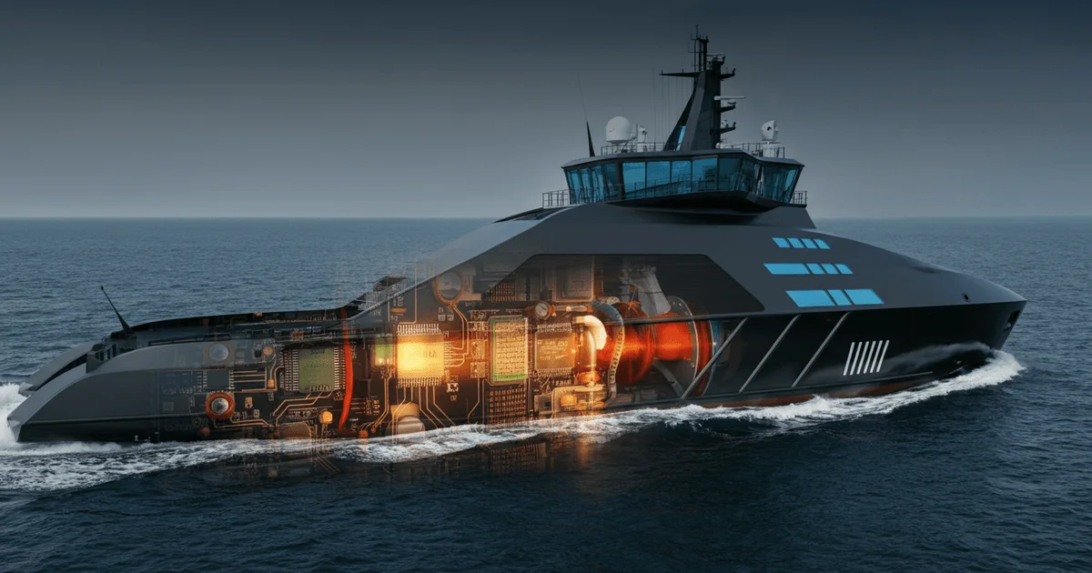
Architecture and Implementation of Microcontroller-Based Control Systems for Modern Marine Electric Propulsion
Modern shipbuilding is undergoing a transformation, actively shifting from traditional diesel and turbine propulsion systems to efficient electric ones. At the heart of this evolution are high-tech marine electric propulsion systems (MEPS), critically dependent on advanced frequency converters (FCs) and their microcontroller-based control systems (MCCS). This article examines the key architectural approaches and design features of such systems, which ensure high maneuverability, efficiency, and reliability for vessels.
Evolution and Components of Marine Electric Propulsion Systems
The development of marine electric propulsion systems (MEPS) over recent decades is driven by their significant advantages over traditional mechanical installations. MEPS offer enhanced maneuverability, improved fuel efficiency, and reduced noise, which is particularly crucial for specialized vessels such as icebreakers, tugboats, and emergency rescue vessels. A key factor in the widespread adoption of MEPS has been the advancement of transistor-based power conversion technology, enabling the creation of powerful frequency converters (FCs) to control propulsion electric motors (PEMs) and thrusters. This has also facilitated the transition to AC MEPS and the integration of the propulsion system with the vessel's overall electrical power system.
A typical modern MEPS structure includes:
- Propulsion electric motors (PEMs), most commonly asynchronous.
- Semiconductor frequency converters (FCs) with their control systems (FC CS).
- Power transformers (optional).
- Electrical switchgear.
FCs, forming the heart of MEPS, are built upon voltage rectifiers (controlled or uncontrolled) and autonomous voltage inverters (AVIs). Active Front End (AFE) rectifiers and AVIs are typically implemented using IGBT transistors, while uncontrolled rectifiers (UCRs) utilize diodes. AFE rectifiers demonstrate superiority due to their ability to maintain a desired power factor, minimize distortions in the vessel's electrical grid, and support energy recuperation during braking, thereby increasing overall system efficiency. FC control systems (FC CS) perform a wide range of tasks: from regulating PEM speed and torque to ensuring startup, stabilization, power limitation, braking, and reversal. They also process commands from various local operator panels (LOPs), collect and transmit diagnostic information to the ship's control system (SCS), manage transitions between operating modes, and provide FC protection in emergency situations. Software development for FC CS requires the application of specialized algorithms for asynchronous motor control. Programmable Logic Controllers (PLCs) are often integrated to perform auxiliary functions, such as processing sensor signals, controlling actuators, and implementing communication interfaces with other systems.
Architectural Approaches to Frequency Converter Control Systems
In the field of microprocessor technology for FC CS, there is a clear trend towards increased integration, enhanced functionality, and reduced size and weight. This leads to the development of compact control units where multiple boards are housed within a single enclosure, with minimal spacing and plug-in connections, often in a metal casing to improve electromagnetic compatibility (EMC) and reliability. Distributed systems, where boards are located at significant distances (over 25 cm) and connected by wires, are less preferred due to lower EMC and reliability in the strong electromagnetic fields characteristic of power electronics.
Modern FC CS most commonly employ a distributed-centralized structure, comprising:
- Local Control Systems (LCS): Responsible for the control, monitoring, and protection of individual transistor converters (TCs), such as AFE rectifiers or AVIs. The number of LCSs corresponds to the number of TCs in the FC (a minimum of two).
- Central Control System (CCS): Coordinates the operation of the LCSs, facilitates information exchange with local operator panels (LOPs) and the Ship's Control System (SCS), and provides overall MEPS management.
- Programmable Logic Controller (PLC): An optional component that extends the CCS's capabilities regarding inputs/outputs and interfaces. In high-performance configurations, a PLC can assume the functions of the CCS, significantly simplifying the overall control system structure.
The concept of a Highly Integrated Control Unit (HICU) for FCs involves combining all these components (LCS, CCS, PLC) into a single enclosure. Advantages of HICUs include enhanced EMC, reduced dimensions, and lower cost. However, such integration comes with high development complexity, limitations on the number of integrated LCSs, and increased difficulty in software development and testing. This demands from developers a deep understanding of both hardware and software aspects of the system, as well as methods for ensuring reliability under stringent operational requirements.
Design Solutions for Microcontroller-Based Control Units
Structurally, microcontroller-based FC control systems are divided into single-board and multi-board solutions, each with its specific applications and advantages.
Single-board control units are systems where all electronic components and system functions are implemented on a single printed circuit board. To expand functionality or specialize, such systems often utilize mezzanine cards – additional boards connected in parallel (stacked above) to the main board, performing specific tasks such as hosting microcontrollers, memory modules, or LED indicators. Mezzanine cards can be positioned on both the top and bottom sides of the main board, offering flexibility in layout and component density.
Multi-board control units, in contrast, consist of several printed circuit boards, each performing a specific set of functions. Several main types of multi-board control units are distinguished:
- Control units with a main (mother or system) board: The main board performs central information processing, control, and monitoring functions, while functional boards (e.g., for discrete, analog inputs/outputs, or digital interfaces) are connected perpendicularly to it. This approach ensures modularity and the possibility of easy replacement or upgrade of peripheral functions.
- Control units with a backplane (or cross-board): A backplane serves to electrically connect various functional modules (e.g., power supply module, microcontroller module, I/O module), which plug into it perpendicularly and are often equipped with front panels. This architecture is convenient for creating systems with a high degree of customization and maintainability.
- Control units with multiple functional boards: In this case, boards (e.g., power, digital, analog, interface) are connected directly to each other via connectors, without using a central main or backplane. This option is often applied in specialized systems where size minimization or a particular topology is required.
In multi-board control units, mezzanine cards can also be used for further functional expansion or to increase component density on individual functional boards. The choice of a specific design solution is determined by requirements for reliability, electromagnetic compatibility, cost, size and weight characteristics, software complexity, and the anticipated operating conditions in the marine environment.
Key Takeaways
- Shift to Electric Propulsion: Modern shipbuilding is actively transitioning to electric propulsion systems due to their efficiency, maneuverability, and potential for integration into a vessel's unified electrical power system.
- Role of FCs and FC CS: Frequency converters are a critical component of MEPS, and their microcontroller-based control systems (FC CS) provide precise regulation, protection, and interaction with shipboard systems.
- Architectural Solutions: FC CS employ distributed-centralized architectures with local and central control systems, as well as highly integrated units (HIUs) to enhance reliability and compactness.
- Design Approaches: The development of MCCS encompasses both single-board solutions (with mezzanines) and multi-board systems (with a main board, backplane, or direct connection of functional boards), with the choice depending on scalability requirements and operating conditions.
- Development Complexity: Creating efficient and reliable microcontroller-based control systems for marine FCs demands deep engineering expertise in power electronics, digital signal processing, and embedded software, given the harsh conditions of marine operation.
— Editorial Team










No comments yet.