Arduino & Modbus
In a previous article, we connected the OpenHAB open home automation platform with the Arduino controller using a very simple, text-based protocol. But this solution will perplex us if we want to connect our controller to another system, what should we do?
Modbus is the most famous and widespread standard in industrial automation, it is supported by millions of devices around the world, these devices are easily integrated into a single network and are interfaced with a huge amount of ready-made software. Let's try to use it in our project?
What do we need to know about this standard?
The Modbus protocol uses serial communication lines (for example, RS232, RS485), and the Modbus TCP protocol is designed to transmit data over TCP / IP networks.
Modbus protocol has two transmission modes RTU and ASCII, in ASCII mode each byte is transmitted as two ASCII characters of its hexadecimal representation.
There is only one master in the Modbus network, which at a given interval polls several slave devices, each of which has its own unique address from 1 to 254, the address 0 is broadcast and all devices respond to it, since the master in the network has no address .
The Modbus specification defines two types of data, one bit and 16 bit word. The data is organized into four tables with 16-bit cell addressing; addressing in the tables starts at 0. Separate commands are used to access data from different tables.
How do we connect a Modbus device to OpenHAB? The Modbus Tcp Binding module is responsible for this ; this module operates in the master mode and provides the connection of several slave devices via a serial port or TCP / IP network.
In order to associate an Arduino with it, we need to implement a Modbus slave device in the controller, we will use the Modbus-Master-Slave-for-Arduino library for this .
Download the library and create a sketch by copying the following code into the program editor. If you wish, you can simply download the project with the necessary files from the repository .
Consider the example of our sketch, the basic steps necessary to work with this library.
All library functions are implemented in a single file ModbusRtu.h.
To interact with it, in the program you need to create an object by setting the Modbus address, serial port number, output number that controls transmission (for RS485)
Then define an array of Modbus registers
After that, when starting the program, configure the slave serial port
In the main program loop, it is necessary to call the function for processing Modbus messages
And after that you can process the received data and save the necessary variables in the Modbus registers.
The standard provides a separate table for each data type, but the feature of the applied library is that all the registers are stored in one array in the form of overlapping tables, so the structure of the controller registers will look like this:
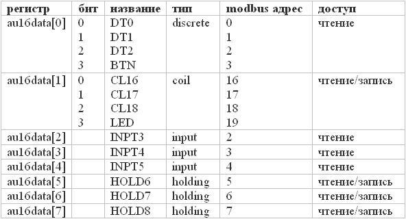
To demonstrate how to work with different registers, the data from registers with type coil will be copied to a register with type discrete, and from registers with type holding to registers with type input. In addition, the state of the button will be saved in the third bit of the register au16data [0] (discrete), and the value of the third bit of the register au16data [1] (coil) is displayed on the LED.
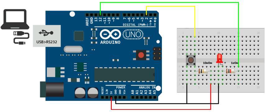
We will finalize the controller layout, which was assembled for previous experiments, switch the LED from 13 to 12 output. Usually on the board of the Arduino itself there is already an LED connected to pin 13, in our program it will become an indicator of the status of work. Now connect the USB cable to the computer, compile and download the program to the controller.
It's time to start the test. The Modbus emulator of the master device greatly facilitates the work at this stage, there are several good, and free programs on the network, here are some of them:
www.focus-sw.com/fieldtalk/modpoll.html
qmodbus.sourceforge.net
www.mikont. com / products / EAT-Console.html
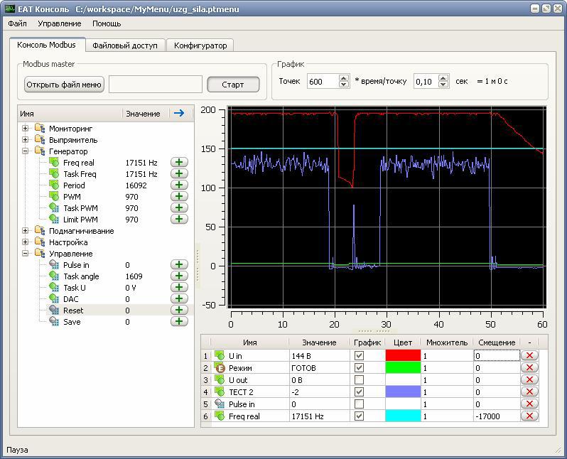
Among them, we can mention the EAT-Console utility which allows not only managing and polling Modbus devices, but also displays data in graphical form, which is very convenient when debugging work with various sensors, for example, humidity, pressure and temperature sensors. Before starting work with the program and its configurator, I recommend that you familiarize yourself with the documentation .
To install the emulator, you need to download the archive and unzip it to the C: \ arduino \ EATConsole folder, then open the Eclipse download page , download the Eclipse IDE for Java Developers and unzip it to the C: \ arduino \ eclipse folder, then copy the files from the C: folder \ arduino \ EATConsole \ eclipse \ plugins to the folder C: \ arduino \ eclipse \ plugins.
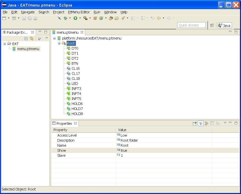
To create a configuration, you need to run C: \ arduino \ eclipse \ eclipse.exe, create an empty project, copy the empty file C: \ arduino \ EATConsole \ menu.ptmenu into it and add items in the editor according to the following table. If you downloaded the project from the repository , then in it, in the EATConsole folder, there is already a prepared menu.ptmenu file.
Type - type of menu item EATConsole.
Address - address of the data register.
Bit - bit number in the register.
Name - the name of the menu item.
Point - the number of decimal places after the point.
Slave - Modbus address of the controller.
Now save and copy the menu.ptmenu file to the C: \ arduino \ EATConsole directory, for this you can right-click on the file directly in Eclipse, select “Copy” in the context menu, and then paste it into the C: \ arduino folder in Explorer \ EATConsole.
After that, run C: \ arduino \ EATConsole \ EATConsole.exe, set up a serial connection by selecting the File \ Settings menu item, in the dialog box indicate the port number, speed 9600, 8 data bits, 1 stop bit.
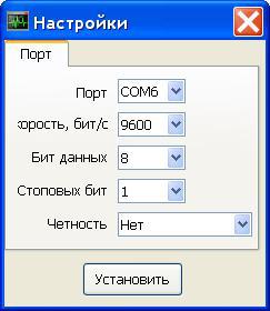
* The program works with ports 1 to 8, and if the Arduino USB adapter is on a port with a large number, you will have to open the Windows device manager and change the port number for it.
When all the settings have been entered, click the “Install” button, immediately after that the program will start polling the device and if something goes wrong a message will appear - NO COMMUNICATION. If everything was done correctly and the connection is what you can verify by flashing the status indicator (LED on pin 13), then it's time to start testing our controller.
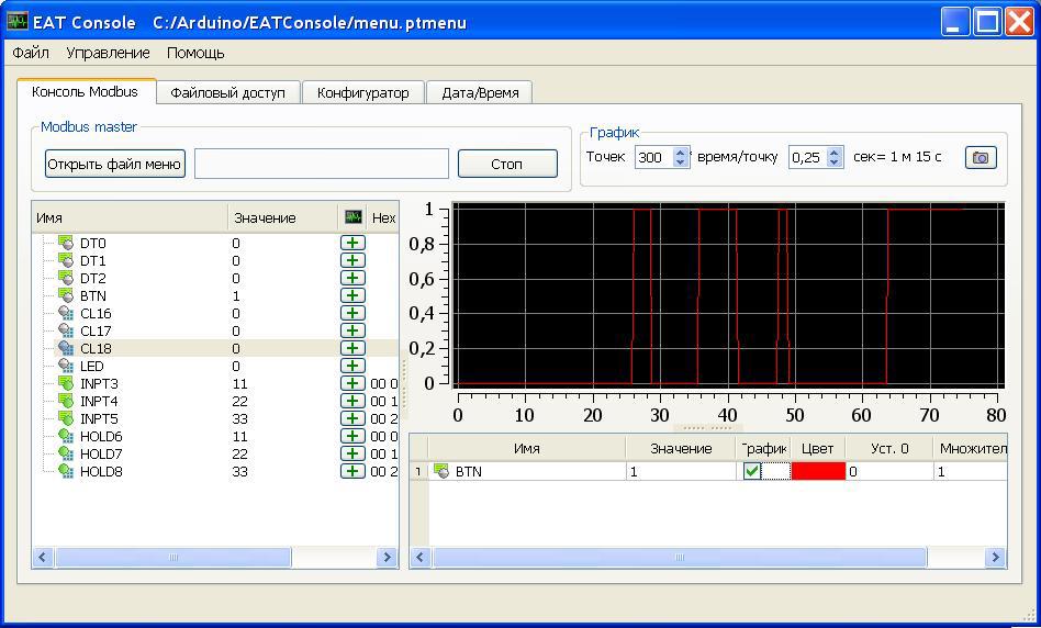
Let's try to change the value in the registers HLD0 ... HLD2 and СL0 ... СL2, while the value in the corresponding register IN0..IN2 and DT0..DT2 should change, then we will press the layout button, and the value should change in the BTN field, click on the LED field , the LED should light up or go out.
What we got as a result of our work:
1 got acquainted with the basics of the Modbus protocol;
2 created a sketch that turns Arduino into a Modbus slave device and allows you to read and write several Modbus registers with different data types;
3 we tested the exchange with the controller using the functions emulator of the Modbus master device, for which we created a configuration corresponding to the structure of the controller registers.
Conclusions
LibraryModbus-Master-Slave-for-Arduino is easy to use, allows you to create a Modbus slave device that works correctly with a software emulator. The compiled example takes a little more than 5kb of program memory, so there is enough space left in the controller to add the necessary functionality.
The Modbus standard is open and popular, but it has a number of drawbacks - the standard defines only two types of data, the
protocol requires constant exchange between the master and slave devices, you have to manually configure the system.
Having some drawbacks, the protocol is quite suitable for use in the controller of home automation systems, especially if docking with various software is required.
The next time Let's connect the controller to the OpenHAB platform.
Modbus is the most famous and widespread standard in industrial automation, it is supported by millions of devices around the world, these devices are easily integrated into a single network and are interfaced with a huge amount of ready-made software. Let's try to use it in our project?
What do we need to know about this standard?
The Modbus protocol uses serial communication lines (for example, RS232, RS485), and the Modbus TCP protocol is designed to transmit data over TCP / IP networks.
Modbus protocol has two transmission modes RTU and ASCII, in ASCII mode each byte is transmitted as two ASCII characters of its hexadecimal representation.
There is only one master in the Modbus network, which at a given interval polls several slave devices, each of which has its own unique address from 1 to 254, the address 0 is broadcast and all devices respond to it, since the master in the network has no address .
The Modbus specification defines two types of data, one bit and 16 bit word. The data is organized into four tables with 16-bit cell addressing; addressing in the tables starts at 0. Separate commands are used to access data from different tables.
| Discrete inputs | 1 bit | only reading |
| Coils | 1 bit | read and write |
| Input registers | 16 bit | only reading |
| Holding registers | 16 bit | read and write |
How do we connect a Modbus device to OpenHAB? The Modbus Tcp Binding module is responsible for this ; this module operates in the master mode and provides the connection of several slave devices via a serial port or TCP / IP network.
In order to associate an Arduino with it, we need to implement a Modbus slave device in the controller, we will use the Modbus-Master-Slave-for-Arduino library for this .
Download the library and create a sketch by copying the following code into the program editor. If you wish, you can simply download the project with the necessary files from the repository .
Consider the example of our sketch, the basic steps necessary to work with this library.
All library functions are implemented in a single file ModbusRtu.h.
To interact with it, in the program you need to create an object by setting the Modbus address, serial port number, output number that controls transmission (for RS485)
Modbus slave(ID, 0, 0);
Then define an array of Modbus registers
uint16_t au16data[11];
After that, when starting the program, configure the slave serial port
slave.begin(9600);
In the main program loop, it is necessary to call the function for processing Modbus messages
state = slave.poll(au16data, 11);
And after that you can process the received data and save the necessary variables in the Modbus registers.
#include "ModbusRtu.h"
#define ID   1      // адрес ведомого
#define btnPin  2   // номер входа, подключенный к кнопке
#define stlPin  13  // номер выхода индикатора работы
                    // расположен на плате Arduino
#define ledPin  12  // номер выхода светодиода
//Задаём ведомому адрес, последовательный порт, выход управления TX
Modbus slave(ID, 0, 0);
boolean led;
int8_t state = 0;
unsigned long tempus;
// массив данных modbus
uint16_t au16data[11];
void setup() {
  // настраиваем входы и выходы
  io_setup();
  // настраиваем последовательный порт ведомого
  slave.begin( 9600 );
  // зажигаем светодиод на 100 мс
  tempus = millis() + 100;
  digitalWrite(stlPin, HIGH );
}
void io_setup() {
  digitalWrite(stlPin, HIGH );
  digitalWrite(ledPin, LOW );
  pinMode(stlPin, OUTPUT);
  pinMode(ledPin, OUTPUT);
  pinMode(btnPin, INPUT);
}
void loop() {
  // обработка сообщений
  state = slave.poll( au16data, 11);
  // если получили пакет без ошибок - зажигаем светодиод на 50 мс
  if (state > 4) {
    tempus = millis() + 50;
    digitalWrite(stlPin, HIGH);
  }
  if (millis() > tempus) digitalWrite(stlPin, LOW );
  //обновляем данные в регистрах Modbus и в пользовательской программе
  io_poll();
}
void io_poll() {
  //Копируем Coil[1] в Discrete[0]
  au16data[0] = au16data[1];
  //Выводим значение регистра 1.3 на светодиод
  digitalWrite( ledPin, bitRead( au16data[1], 3 ));
  //Сохраняем состояние кнопки в регистр 0.3
  bitWrite( au16data[0], 3, digitalRead( btnPin ));
  //Копируем Holding[5,6,7] в Input[2,3,4]
  au16data[2] = au16data[5];
  au16data[3] = au16data[6];
  au16data[4] = au16data[7];
  //Сохраняем в регистры отладочную информацию
  au16data[8] = slave.getInCnt();
  au16data[9] = slave.getOutCnt();
  au16data[10] = slave.getErrCnt();
}
The standard provides a separate table for each data type, but the feature of the applied library is that all the registers are stored in one array in the form of overlapping tables, so the structure of the controller registers will look like this:
To demonstrate how to work with different registers, the data from registers with type coil will be copied to a register with type discrete, and from registers with type holding to registers with type input. In addition, the state of the button will be saved in the third bit of the register au16data [0] (discrete), and the value of the third bit of the register au16data [1] (coil) is displayed on the LED.
We will finalize the controller layout, which was assembled for previous experiments, switch the LED from 13 to 12 output. Usually on the board of the Arduino itself there is already an LED connected to pin 13, in our program it will become an indicator of the status of work. Now connect the USB cable to the computer, compile and download the program to the controller.
It's time to start the test. The Modbus emulator of the master device greatly facilitates the work at this stage, there are several good, and free programs on the network, here are some of them:
www.focus-sw.com/fieldtalk/modpoll.html
qmodbus.sourceforge.net
www.mikont. com / products / EAT-Console.html
Among them, we can mention the EAT-Console utility which allows not only managing and polling Modbus devices, but also displays data in graphical form, which is very convenient when debugging work with various sensors, for example, humidity, pressure and temperature sensors. Before starting work with the program and its configurator, I recommend that you familiarize yourself with the documentation .
To install the emulator, you need to download the archive and unzip it to the C: \ arduino \ EATConsole folder, then open the Eclipse download page , download the Eclipse IDE for Java Developers and unzip it to the C: \ arduino \ eclipse folder, then copy the files from the C: folder \ arduino \ EATConsole \ eclipse \ plugins to the folder C: \ arduino \ eclipse \ plugins.
To create a configuration, you need to run C: \ arduino \ eclipse \ eclipse.exe, create an empty project, copy the empty file C: \ arduino \ EATConsole \ menu.ptmenu into it and add items in the editor according to the following table. If you downloaded the project from the repository , then in it, in the EATConsole folder, there is already a prepared menu.ptmenu file.
| Type | Address | Bit | Name | Point | Slave |
| Display boolean | 0 | 0 | Dt0 | 1 | |
| Display boolean | 0 | 1 | Dt1 | 1 | |
| Display boolean | 0 | 2 | Dt2 | 1 | |
| Display boolean | 0 | 3 | BTN | 1 | |
| Input boolean | 1 | 0 | CL16 | 1 | |
| Input boolean | 1 | 1 | CL17 | 1 | |
| Input boolean | 1 | 2 | CL18 | 1 | |
| Input boolean | 1 | 3 | LED | 1 | |
| Display integer | 2 | INPT3 | 0 | 1 | |
| Display integer | 3 | INPT4 | 0 | 1 | |
| Display integer | 4 | INPT5 | 0 | 1 | |
| Display integer | 5 | HOLD6 | 0 | 1 | |
| Display integer | 6 | HOLD7 | 0 | 1 | |
| Display integer | 7 | HOLD8 | 0 | 1 |
Type - type of menu item EATConsole.
Address - address of the data register.
Bit - bit number in the register.
Name - the name of the menu item.
Point - the number of decimal places after the point.
Slave - Modbus address of the controller.
Now save and copy the menu.ptmenu file to the C: \ arduino \ EATConsole directory, for this you can right-click on the file directly in Eclipse, select “Copy” in the context menu, and then paste it into the C: \ arduino folder in Explorer \ EATConsole.
After that, run C: \ arduino \ EATConsole \ EATConsole.exe, set up a serial connection by selecting the File \ Settings menu item, in the dialog box indicate the port number, speed 9600, 8 data bits, 1 stop bit.
* The program works with ports 1 to 8, and if the Arduino USB adapter is on a port with a large number, you will have to open the Windows device manager and change the port number for it.
When all the settings have been entered, click the “Install” button, immediately after that the program will start polling the device and if something goes wrong a message will appear - NO COMMUNICATION. If everything was done correctly and the connection is what you can verify by flashing the status indicator (LED on pin 13), then it's time to start testing our controller.
Let's try to change the value in the registers HLD0 ... HLD2 and СL0 ... СL2, while the value in the corresponding register IN0..IN2 and DT0..DT2 should change, then we will press the layout button, and the value should change in the BTN field, click on the LED field , the LED should light up or go out.
What we got as a result of our work:
1 got acquainted with the basics of the Modbus protocol;
2 created a sketch that turns Arduino into a Modbus slave device and allows you to read and write several Modbus registers with different data types;
3 we tested the exchange with the controller using the functions emulator of the Modbus master device, for which we created a configuration corresponding to the structure of the controller registers.
Conclusions
LibraryModbus-Master-Slave-for-Arduino is easy to use, allows you to create a Modbus slave device that works correctly with a software emulator. The compiled example takes a little more than 5kb of program memory, so there is enough space left in the controller to add the necessary functionality.
The Modbus standard is open and popular, but it has a number of drawbacks - the standard defines only two types of data, the
protocol requires constant exchange between the master and slave devices, you have to manually configure the system.
Having some drawbacks, the protocol is quite suitable for use in the controller of home automation systems, especially if docking with various software is required.
The next time Let's connect the controller to the OpenHAB platform.