STM32L0538-DISCO: Short Description + Interesting Application
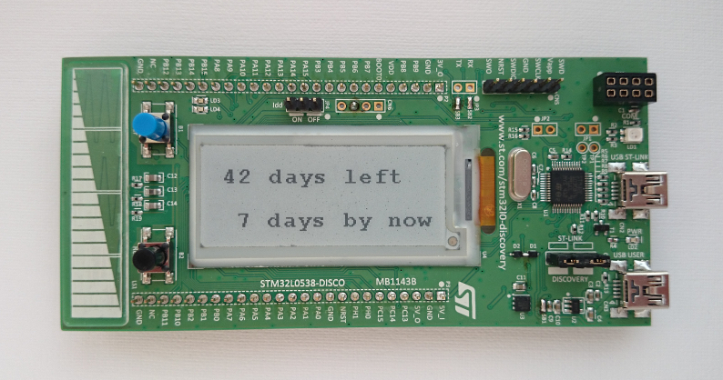
For quite some time now, a new motherboard from the discovery series from STMicroelectronics has appeared on sale. I think the habrasociety will be interested in getting to know her better. Under the cut, you will find a brief overview of the new demo board and an interesting example of its application.
The board is designed to demonstrate the capabilities of STM32L053C8, a representative of a series of ultra-low power microcontrollers. In addition to it, another ST chip (STM32L152CCT6) is installed on the board, which measures the current consumed by the main MK in various modes. Traditionally, the programmer / debugger ST-Link (version 2.1) is implemented on the board, which allows flashing and debugging both the target MK and external chips via the SWD interface. ST-Link 2.1 also implements a USB-COM converter, and also appears in the system as a removable disk, allowing you to flash the microcontroller by simply copying the binary file.
Useless remark
Так как ST-Link тоже реализован на чипе от ST (STM32F103CBT6), получается, что купив одну отладочную плату, получаешь целых 3 разных МК на ней!
The main feature of the board is a display made using electronic ink technology. The display is not large (2.04 inches, 172x72) and it is far from the brothers installed in electronic books, but it is quite suitable for displaying a variety of information.
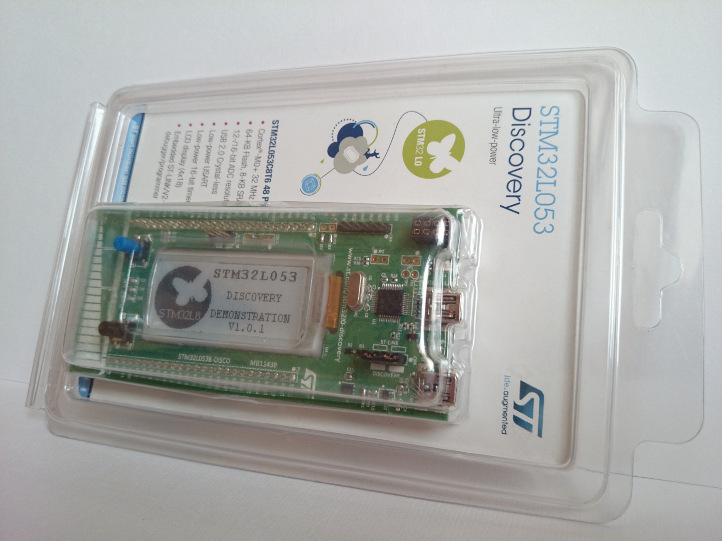
The board comes with a demo firmware that works in two modes (however, only the first one is sensible): measuring and displaying the current consumed by the STM32L053C8 on the e-ink screen or in USB mouse mode. The choice of modes is carried out by the touch slider.
Board Application Concept
When I received the board and saw the ST logo on a de-energized screen, I immediately wanted to make an autonomous, practically energy-saving device that would display some rarely changing information. You can generally forget about it, but it will still show something after months and even years. For example, how many days are left before an event. And so the concept of the device was born: an electronic paper counter of the days of the countdown, which will always remind you of the inexorable approach of the deadline, new year, birthday (underline as necessary).
No sooner said than done! After some time, the debug board turned into a device. A small battery is used for power. You can use any with a voltage of 3 V, I have this "tablet" CR2032 in the holder. The microcontroller is in sleep mode with the RTC module on. When the next day comes, RTC wakes up the controller, which updates the counter of the countdown of days on the screen. Since the screen consumes energy only during the redrawing process, all the main time the battery feeds the clock in the controller and only occasionally does the energy go to update the counter. USB is used for configuration (more precisely, UART via a USB-COM converter provided by the debugger on the board). The board, along with the battery, fits perfectly in the original plastic packaging. In the process of implementation, another function was added - an increasing counter of days, which is reset by pressing the User button. It can be useful for motivation, for example: “I don’t smoke 38 days”, “I didn’t miss the workout for 15 days”, etc. Well, or something like: "56 days without incidents."
Implementation
Now about what needs to be done to make it work. Since on the board, in addition to the STM32L053C8 and the display, there are two other MKs, you need to modify it so as not to waste battery power.
Finalization in pictures
1. Выпаиваем перемычку SB13 и резисторы R44, R50:

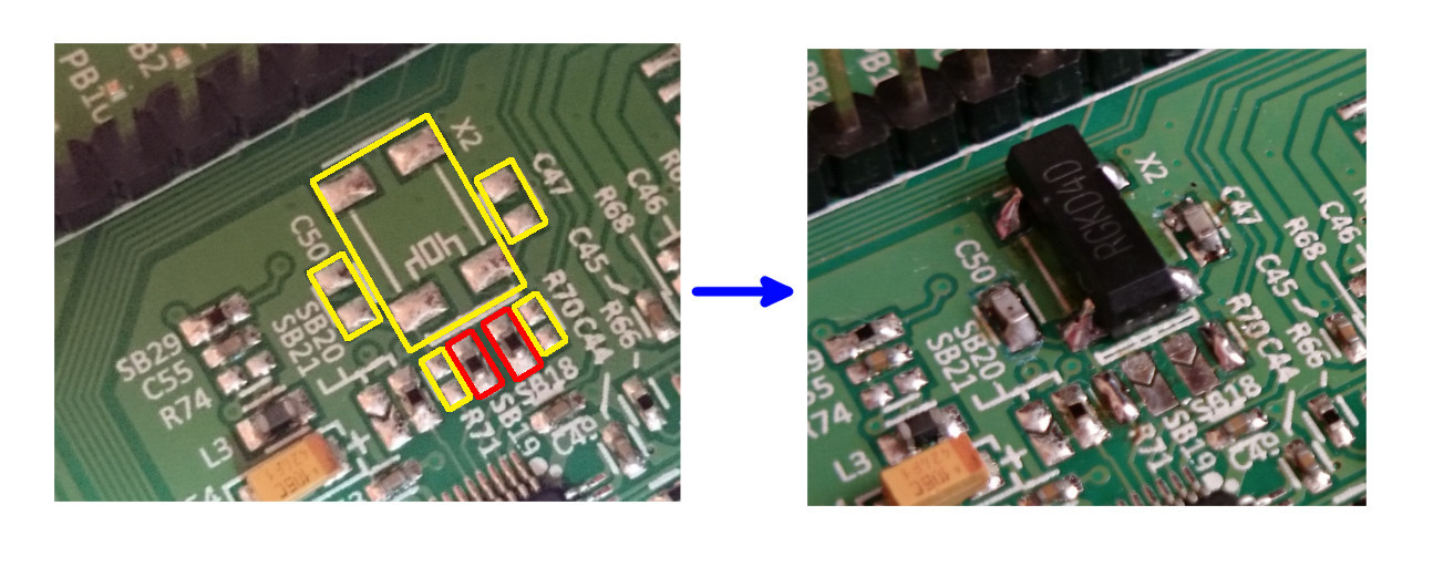
2. Монтируем на плату кварц X2 (32.768 кГц), конденсаторы C47 и С50 (~10 пФ), резисторы R70 и R71 замыкаем каплями припоя. Также желательно выпаять резисторы-перемычки SB18, SB19 (их можно впаять на место R70 и R71).
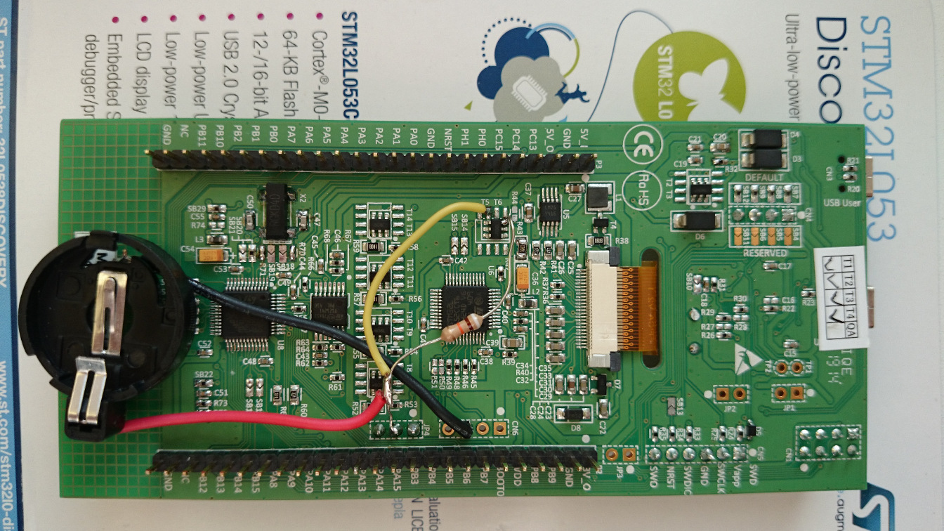
3. Перерезаем дорожку на плате возле транзистора T6, добавляем резистор на 100 кОм, держатель для батарейки CR2032:

Должно получится вот так:
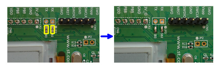
4. Замыкаем перемычки SB2, SB3:
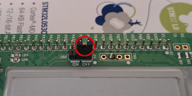
5. Снимаем джампер с разъёма JP4:
Вот и всё!
2. Монтируем на плату кварц X2 (32.768 кГц), конденсаторы C47 и С50 (~10 пФ), резисторы R70 и R71 замыкаем каплями припоя. Также желательно выпаять резисторы-перемычки SB18, SB19 (их можно впаять на место R70 и R71).
3. Перерезаем дорожку на плате возле транзистора T6, добавляем резистор на 100 кОм, держатель для батарейки CR2032:
Должно получится вот так:
4. Замыкаем перемычки SB2, SB3:
5. Снимаем джампер с разъёма JP4:
Вот и всё!
More about hardware changes (caution, many letters)
Нужно запитать только STM32L053C8 и дисплей. Штатного способа этого сделать не предусмотрено. Есть контакт 5V_in, но от него будет питаться ещё и ST-Link вместе с токоизмерительным МК. Всё это питается через стабилизаторы, на которых тоже будут потери. Нам же нужно добавить батарейку, при этом максимально возможно сохранить функционал платы (можно конечно выпаять все лишнее, но это не наш путь).
Перемычку SB13 нужно выпаять, чтобы отключить сигнал сброса T_NRST, который генерирует ST-Link. Без этого сигнала можно обойтись, STM32L053C8 будет прошиваться и без него (разве что придется нажимать на кнопку сброса, если он будет в спящем режиме).
Резистор R50 нужно убрать, так как через него токоизмерительный МК паразитно питается от шины VDD, на которую мы подадим напряжение батарейки.
Для работы RTC необходим источник тактовой частоты. Внешний «часовой» кварц на 32.768 кГц, на плате отсутствует (но под него предусмотрено место) и чтобы избежать лишних переделок, я сначала попробовал использовать встроенный в МК RC генератор. Точность такого решения оказалась абсолютно неприемлемой (часы убегали на полчаса в день), поэтому нужно впаять кварц X2, два конденсатора C47 и С50 (~10 пФ 0603) для него и подключить его к МК. Подключать кварц предполагается запаяв два резистора R70 и R71, я же обошёлся просто каплями припоя. Также желательно выпаять перемычки SB18 и SB19 (их можно впаять на место R70 и R71), чтобы сигнальные дорожки кварца не выходили на разъёмы платы.
Ещё нужно перерезать одну дорожку (не люблю резать дорожки, но здесь это меньшее из зол). Дело в том, что STM32L053C8 через транзистор T6 управляет питанием дисплея и эту возможность необходимо сохранить, так как если запитать дисплей напрямую от батарейки и не выключать его на периоды бездействия, будет лишнее потребление. Транзистор T6 подаёт питание на дисплей с шины 3V3, которая подключена к токоизмерительному МК и его обвязке. Так как мы не хотим тратить на него энергию, мы вообще не будем питать шину 3V3 и подключим плюс батарейки на шину VDD. Значит и на исток транзистора T6 нужно подать шину VDD, а 3V3 убрать. Вот почему нужно отрезать эту линию от него и подать в эту точку напряжение батарейки.
Ещё придётся выпаять резистор R44. Его можно было бы и оставить, но тогда пришлось бы заниматься фигурным вырезанием меди, поэтому его проще выпаять и заменить выводным номиналом в 100 кОм. Этот резистор подтягивает затвор транзистора к питанию для предотвращения случайного открытия.
Батарейка припаивается плюсом к шине VDD, а минусом её нужно подключить к GND. Шина VDD это фактически пины питания STM32L053C8, так что напряжение от батарейки пойдет на него напрямую, без стабилизаторов напряжения и какой-либо защиты от переполюсовки. Нужно обязательно соблюдать полярность и подавать не больше 3.3 вольт (максимально допустимо 3.6).
И последняя доработка: замыкание перемычек SB2, SB3. Для установки времени и даты используется последовательный порт МК (USART1) подключенный к UART-USB преобразователю, реализованному на ST-LINK v2.1. Это подключение и осуществляется замыканием перемычек SB2, SB3.
Перемычку SB13 нужно выпаять, чтобы отключить сигнал сброса T_NRST, который генерирует ST-Link. Без этого сигнала можно обойтись, STM32L053C8 будет прошиваться и без него (разве что придется нажимать на кнопку сброса, если он будет в спящем режиме).
Резистор R50 нужно убрать, так как через него токоизмерительный МК паразитно питается от шины VDD, на которую мы подадим напряжение батарейки.
Для работы RTC необходим источник тактовой частоты. Внешний «часовой» кварц на 32.768 кГц, на плате отсутствует (но под него предусмотрено место) и чтобы избежать лишних переделок, я сначала попробовал использовать встроенный в МК RC генератор. Точность такого решения оказалась абсолютно неприемлемой (часы убегали на полчаса в день), поэтому нужно впаять кварц X2, два конденсатора C47 и С50 (~10 пФ 0603) для него и подключить его к МК. Подключать кварц предполагается запаяв два резистора R70 и R71, я же обошёлся просто каплями припоя. Также желательно выпаять перемычки SB18 и SB19 (их можно впаять на место R70 и R71), чтобы сигнальные дорожки кварца не выходили на разъёмы платы.
Ещё нужно перерезать одну дорожку (не люблю резать дорожки, но здесь это меньшее из зол). Дело в том, что STM32L053C8 через транзистор T6 управляет питанием дисплея и эту возможность необходимо сохранить, так как если запитать дисплей напрямую от батарейки и не выключать его на периоды бездействия, будет лишнее потребление. Транзистор T6 подаёт питание на дисплей с шины 3V3, которая подключена к токоизмерительному МК и его обвязке. Так как мы не хотим тратить на него энергию, мы вообще не будем питать шину 3V3 и подключим плюс батарейки на шину VDD. Значит и на исток транзистора T6 нужно подать шину VDD, а 3V3 убрать. Вот почему нужно отрезать эту линию от него и подать в эту точку напряжение батарейки.
Ещё придётся выпаять резистор R44. Его можно было бы и оставить, но тогда пришлось бы заниматься фигурным вырезанием меди, поэтому его проще выпаять и заменить выводным номиналом в 100 кОм. Этот резистор подтягивает затвор транзистора к питанию для предотвращения случайного открытия.
Батарейка припаивается плюсом к шине VDD, а минусом её нужно подключить к GND. Шина VDD это фактически пины питания STM32L053C8, так что напряжение от батарейки пойдет на него напрямую, без стабилизаторов напряжения и какой-либо защиты от переполюсовки. Нужно обязательно соблюдать полярность и подавать не больше 3.3 вольт (максимально допустимо 3.6).
И последняя доработка: замыкание перемычек SB2, SB3. Для установки времени и даты используется последовательный порт МК (USART1) подключенный к UART-USB преобразователю, реализованному на ST-LINK v2.1. Это подключение и осуществляется замыканием перемычек SB2, SB3.
After the above manipulations, the current consumption of the board in the idle period (MK in Standby with RTC mode) became 0.7 μA, which is extremely small and the batteries should last for a long time (years). At the same time, it remains possible to use the built-in ST-Link for STM32L053C8 firmware. You can flash without disconnecting the battery, the main thing is that the JP4 jumper is absent. If you want to work with the board without a battery, then you need to disconnect the battery and put the JP4 jumper back (OFF position) so that the STM32L053C8 is powered by the board. But if the battery is connected and the JP4 jumper is dressed, the board cannot be connected to USB, because then the voltage from the board will go to the battery!
Program
The program is written in EmBlocks 2.30 (the ARM-GCC compiler) and is based on examples of working with peripherals from the STM32Cube_FW_L0_V1.1.0 package. In general, I wanted to use CoIDE, but it does not yet support this MK.
A few words about the algorithm of the program and how to use the device. After a reset, it checks whether the date and time are set. If not, then the screen prompts you to set the clock using the terminal:
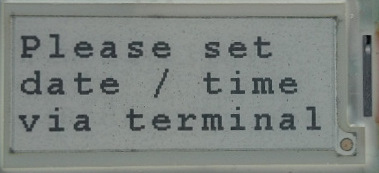
To do this, you need to connect the board to the computer using the USB connector (central). In the terminal, set the speed / parity: 9600, 8n1, open the connection, and press the Reset button on the board. A prompt should appear in the terminal to set the date and time. You also need to set the number of days for the countdown. After successful configuration, 2 counters are displayed on the screen: increase and decrease the number of days. Then the microcontroller goes into Standby mode (the most energy-efficient). It can be awakened by the advent of a new day (at midnight), by pressing the Reset button or the User button. When a new day arrives, both counters are displayed on the screen. To reset the incrementing counter, press the User button (it is strictly forbidden to do this at midnight!). To view the current time and date, press the reset button. If you need to change the time and date (for example, to adjust the clock) or set a new value for the countdown counter, then this can be done if after pressing the Reset button, within 10 seconds, establish a connection via the terminal (press Enter). The screen will then:

Sources and the finished hex file are available on github .
Possible enhancements:
- Cyrillic support so that you can describe the event on the screen itself, for example: “There are 365 days left until the new year”;
- refuse to configure through the terminal in favor of a removable disk emulation. Then, to configure, you will need to edit the text file in which to set the date / time, the new counter value and the displayed phrase.