January 16, 2015 at 08:13
The troubleshooting algorithm in the LED lamp driver or Hercule Poirot rests
Recently, a friend asked me to help with a problem. He is engaged in the development of LED lamps, simultaneously trading them. He has accumulated a certain number of lamps that are not working properly. Outwardly, this is expressed as follows: when turned on, the lamp flashes for a short time (less than a second), goes out for a second and so repeats endlessly. He gave me three such lamps for research, I solved the problem, the malfunction turned out to be very interesting (right in the style of Hercule Poirot) and I want to talk about the way to find the malfunction.
The LED lamp looks like this:
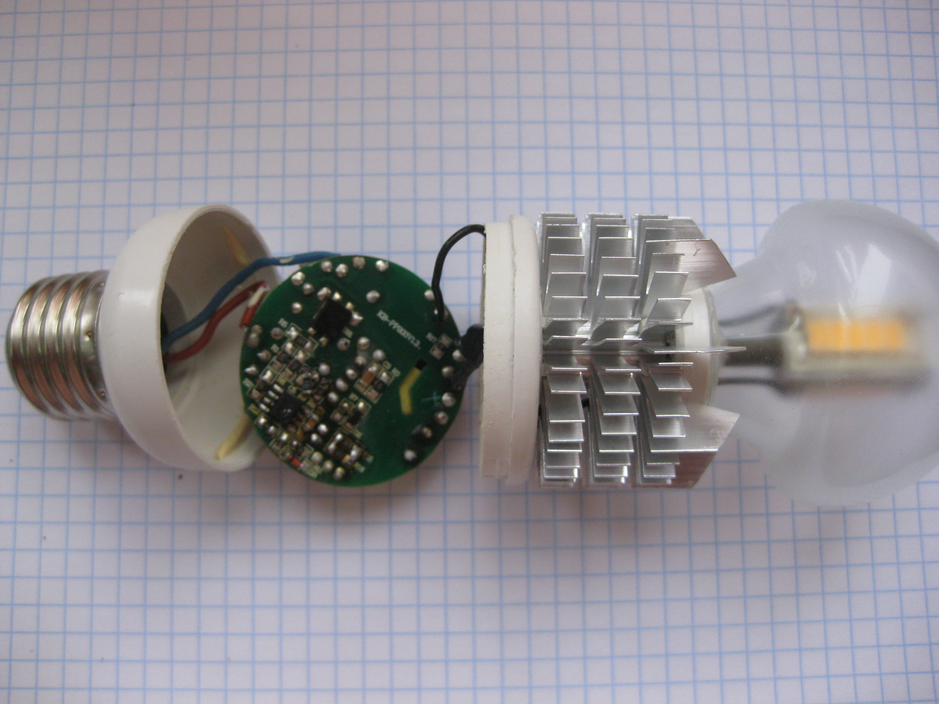
Figure 1. The appearance of the disassembled LED lamp
The developer applied an interesting solution - the heat from the working LEDs is taken by a heat pipe and transferred to a classic aluminum radiator. According to the author, this solution allows you to ensure the correct thermal regime for the LEDs, minimizing thermal degradation and ensuring the maximum possible life of the diodes. Along the way, the service life of the diode power driver increases, since the driver board is removed from the thermal circuit and the temperature of the board does not exceed 50 degrees Celsius.
This solution - to separate the functional areas of light emission, heat removal and generation of supply current - made it possible to obtain high lamp performance in terms of reliability, durability and maintainability.
Oddly enough, the minus of such lamps directly follows from its advantages - manufacturers do not need a durable lamp :). Does everyone remember the story of the conspiracy of manufacturers of incandescent lamps about a maximum service life of 1000 hours?
Well, I can not help but note the characteristic appearance of the product. My "state control" (wife) did not allow me to put these lamps in the chandelier where they are visible.
Back to driver issues.
Here is the driver board:

Figure 2. External view of the LED driver board from the surface mounting side
And from the back:
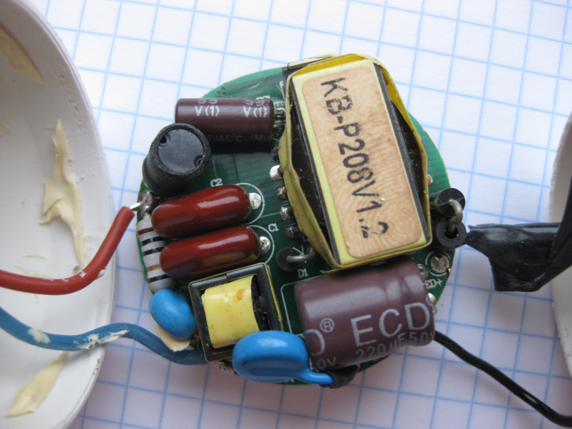
Figure 3. External view of the LED driver board from the power parts side
Studying it under a microscope made it possible to determine the type of control chip - this is MT7930. This is a fly back converter control chip, hung with a variety of protections, like toys for a Christmas tree.
The MT7930 has built-in protection:
• against exceeding the current of the key element
• lowering the supply voltage
• increasing the supply voltage
• short circuit in the load and breaking the load.
• against exceeding the temperature of the crystal.
Declaring protection against short circuits in the load for the current source is more of a marketing nature :) We
could not get a circuit diagram for just such a driver, however, a network search gave several very similar circuits. The closest one is shown in the figure:
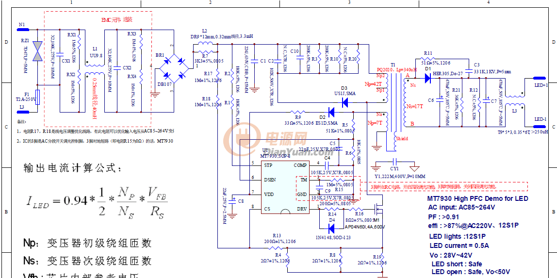
Figure 4. LED Driver MT7930. Schematic electrical circuit
Analysis of this circuit and thoughtful reading of the manual for the microcircuit led me to the conclusion that the source of the blinking problem is the triggering of protection after starting. Those. the initial start-up procedure takes place (lamp flashing - this is it), but then the converter turns off according to some of the protections, the power capacitors are discharged and the cycle starts again.
Attention! The circuit contains life-threatening voltages! Do not repeat without proper understanding what you are doing!
To study the signals with an oscilloscope, you must decouple the circuit from the network so that there is no galvanic contact. For this, I used an isolation transformer. On the balcony in stocks were found two transformers TN36 still Soviet-made, dated 1975. Well, these are eternal devices, massive, filled with completely green varnish. Connected according to the scheme 220 - 24 - 24 -220. Those. first lowered the voltage to 24 volts (4 secondary windings of 6.3 volts each), and then increased it. The presence of several primary windings with taps gave me the opportunity to play with different supply voltages - from 110 volts to 238 volts. Such a solution, of course, is somewhat redundant, but is quite suitable for one-time measurements.

Figure 5. Photo of isolation transformer
From the description of the start in the manual it follows that when power is applied, capacitor C8 starts charging through resistors R1 and R2 with a total resistance of about 600 kΩ. Two resistors are used for safety reasons, so that during the breakdown of one current through this circuit does not exceed a safe value.
So, the power capacitor is slowly charging (this time is about 300-400 ms) and when the voltage on it reaches the level of 18.5 volts, the converter starts the procedure. The microcircuit begins to generate a sequence of pulses on a key field-effect transistor, which leads to voltage on the Na winding. This voltage is used in two ways - for generating feedback pulses for monitoring the output current (circuit R5 R6 C5) and for generating the working voltage of the microcircuit (circuit D2 R9). At the same time, current arises in the output circuit, which leads to the ignition of the lamp.
Why is protection triggered and by which parameter?
First assumption
Is the overvoltage protection tripped?
To verify this assumption, I soldered and checked the resistors in the divider circuit (R5 10 kom and R6 39 kom). Do not check them without evaporating, because they are parallelized through the transformer winding. Elements turned out to be working, but at some point the circuit worked!
I checked the shape and voltage of the signals at all points of the converter with an oscilloscope and was surprised to see that they were all fully certified. No deviations from the norm ...
Gave the scheme to work an hour - everything is OK.
And if you let her cool? After 20 minutes in the off state does not work.
Very good, apparently the matter is in the heating of some element?
But which one? And what element parameters can float away?
At this point, I concluded that there is some element on the converter board that is temperature sensitive. Heating this element fully normalizes the operation of the circuit.
What is this element?
Second assumption
Suspicion fell on the transformer. The problem was thought like this - the transformer, due to manufacturing inaccuracies (say a couple of turns of the winding is not rewound), works in the saturation region and due to a sharp drop in inductance and a sharp increase in current, the current protection of the field key is triggered. This is the resistor R4 R8 R19 in the drain circuit, the signal from which is fed to pin 8 (CS, apparently Current Sense) of the microcircuit and is used for the current OS circuit and, when the 2.4 volt setting is exceeded, disables generation to protect the field effect transistor and transformer from damage. On the test board there are two R15 R16 resistors in parallel with an equivalent resistance of 2.3 ohms.
But as far as I know, the parameters of the transformer deteriorate when heated, i.e. the system behavior should be different - turning on, working for 5-10 minutes and turning it off. The transformer on the board is very massive and its thermal constant is by no means less than a few minutes.
Maybe, of course, it has a short-circuited coil, which disappears when heated?
Soldering the transformer to a guaranteed serviceable one was not possible at that moment (the working board was not yet guaranteed), so I left this option for later when there are absolutely no versions :). Plus the intuitive feeling is not it. I trust my engineering intuition.
At this point, I tested the hypothesis that the current protection was triggered by reducing the current resistor by half by soldering in parallel with the same one - this did not affect the blinking of the lamp.
So, with the current of the field-effect transistor, everything is fine and there is no over current. This was clearly visible by the waveform on the oscilloscope screen. The peak of the sawtooth signal was 1.8 volts and clearly did not reach a value of 2.4 volts, at which the chip turned off the generation.
The circuit was also insensitive to load changes - neither connecting the second head in parallel, nor switching the heated head to cold and vice versa did not change anything.
The third assumption
I investigated the supply voltage of the chip. When operating in normal mode, all voltages were absolutely normal. In blinking mode, too, as far as one could judge by the waveforms on the oscilloscope screen.
As before, the system blinked in a cold state and began to work normally when the transformer leg was heated with a soldering iron. 15 seconds to warm - and everything starts up normally.
Warming the microcircuit with a soldering iron did not give anything.
And it was very embarrassing for the short heating time ... what could change there in 15 seconds?
At some point, he sat down and methodically, logically, the compartment is all guaranteed to work. Once the lamp lights up, it means the start circuits are working.
Once the board is heated, it is possible to start the system and it works for hours, which means that the power systems are in good working order.
It cools down and stops working - something depends on the temperature ... Is there a
crack on the board in the feedback circuit? It cools down and contracts, does the contact break, heats up, expands, and does the contact recover?
I climbed a cold board with a tester - there are no breaks.
What else can interfere with the transition from startup mode to operating mode? !!!
From complete hopelessness, intuitively soldered in parallel to the electrolytic capacitor 10 microfarads at 35 volts for the power supply of the microcircuit is the same.
And then happiness came. Earned!
Replacing the 10 microfarad capacitor with 22 microfarad completely solved the problem.
Here it is, the culprit of the problem:
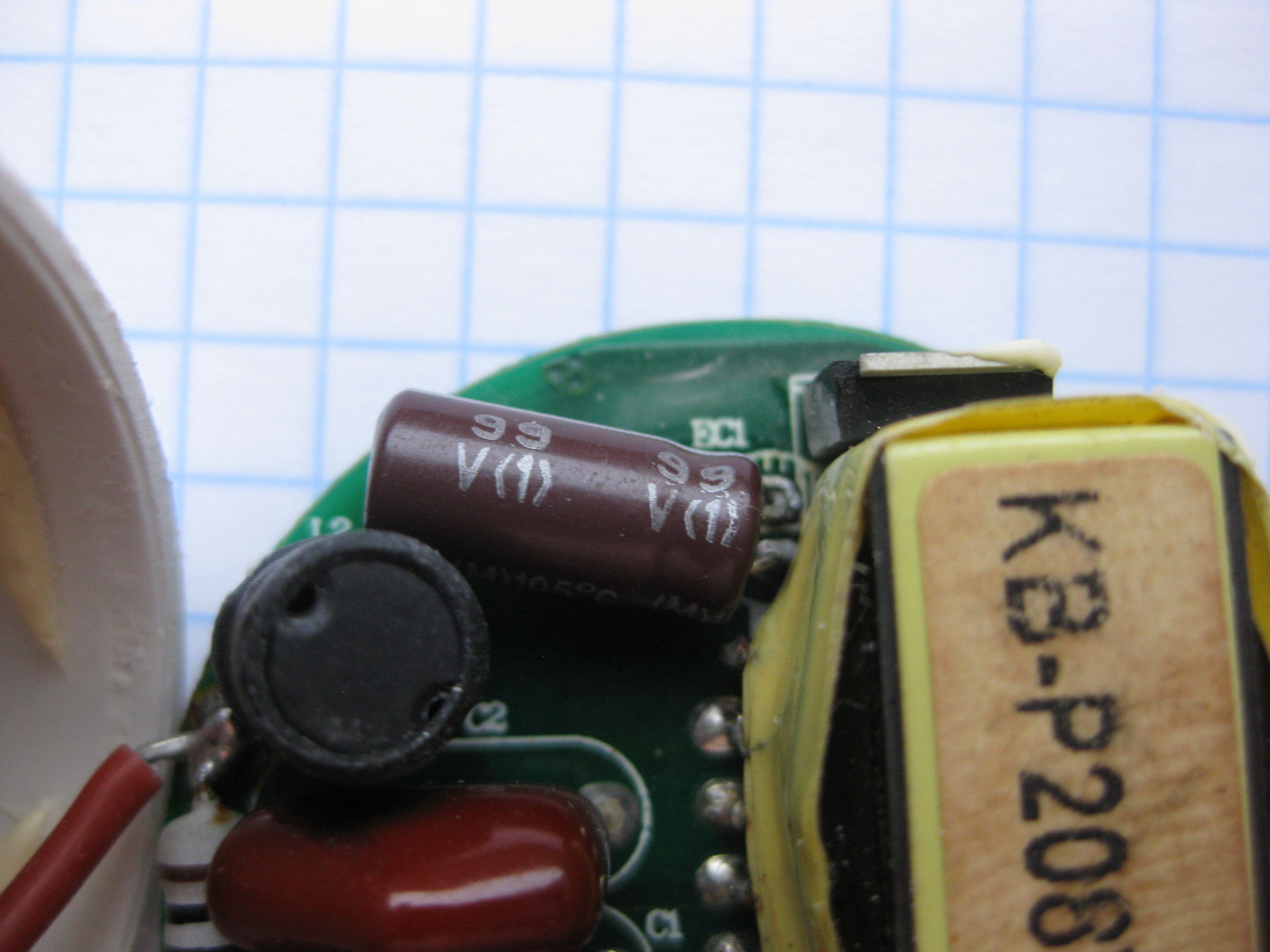
Figure 6. A capacitor with the wrong capacity
Now the malfunction mechanism has become clear. The circuit has two microcircuit power circuits. The first one, which starts, slowly charges the capacitor C8 when 220 volts are supplied through a 600 kΩ resistor. After its charge, the microcircuit begins to generate pulses for the field operator, starting the power part of the circuit. This leads to the generation of power for the microcircuit in the operating mode on a separate winding, which enters the capacitor through a diode with a resistor. The signal from this winding is also used to stabilize the output current.
Until the system enters the operating mode, the microcircuit is powered by the stored energy in the capacitor. And she was missing a little bit - literally a couple or three percent.
The voltage drop turned out to be enough for the microcircuit protection system to operate on reduced power and turn off everything. And the cycle began anew.
The oscilloscope did not succeed in catching this drawdown of the supply voltage - the estimate is too rough. It seemed to me that everything was fine.
Warming up the board increased the capacitor's capacity by the missing percent - and there was already enough energy for a normal start-up.
It is clear why only some of the drivers failed with fully functional elements. A bizarre combination of the following factors played a role:
• The small capacitance of the capacitor in power supply. A positive role was played by the tolerance on the capacitance of electrolytic capacitors (-20% + 80%), i.e. capacities with a nominal value of 10 microfarads in 80% of cases have a real capacitance of about 18 microfarads. Over time, the capacity decreases due to drying of the electrolyte.
• A positive temperature dependence of the capacitance of electrolytic capacitors on temperature. The increased temperature at the place of the output control is literally a couple of degrees and enough capacity for a normal start. If we assume that at the place of the exit control it was not 20 degrees, but 25-27, then this turned out to be enough for almost 100% passing the exit control.
The driver manufacturer saved of course by applying capacities of a lower nominal value compared to the reference design from the manual (22 microfarads are indicated there), but fresh capacities at an elevated temperature and taking into account a spread of + 80% allowed the driver to hand over a batch of drivers. The customer received seemingly working drivers, which over time began to fail for no apparent reason. It would be interesting to know if the manufacturer’s engineers took into account the peculiarities of the behavior of electrolytic capacitors with increasing temperature and the natural dispersion or did it happen by chance?
The LED lamp looks like this:
Figure 1. The appearance of the disassembled LED lamp
The developer applied an interesting solution - the heat from the working LEDs is taken by a heat pipe and transferred to a classic aluminum radiator. According to the author, this solution allows you to ensure the correct thermal regime for the LEDs, minimizing thermal degradation and ensuring the maximum possible life of the diodes. Along the way, the service life of the diode power driver increases, since the driver board is removed from the thermal circuit and the temperature of the board does not exceed 50 degrees Celsius.
This solution - to separate the functional areas of light emission, heat removal and generation of supply current - made it possible to obtain high lamp performance in terms of reliability, durability and maintainability.
Oddly enough, the minus of such lamps directly follows from its advantages - manufacturers do not need a durable lamp :). Does everyone remember the story of the conspiracy of manufacturers of incandescent lamps about a maximum service life of 1000 hours?
Well, I can not help but note the characteristic appearance of the product. My "state control" (wife) did not allow me to put these lamps in the chandelier where they are visible.
Back to driver issues.
Here is the driver board:
Figure 2. External view of the LED driver board from the surface mounting side
And from the back:
Figure 3. External view of the LED driver board from the power parts side
Studying it under a microscope made it possible to determine the type of control chip - this is MT7930. This is a fly back converter control chip, hung with a variety of protections, like toys for a Christmas tree.
The MT7930 has built-in protection:
• against exceeding the current of the key element
• lowering the supply voltage
• increasing the supply voltage
• short circuit in the load and breaking the load.
• against exceeding the temperature of the crystal.
Declaring protection against short circuits in the load for the current source is more of a marketing nature :) We
could not get a circuit diagram for just such a driver, however, a network search gave several very similar circuits. The closest one is shown in the figure:
Figure 4. LED Driver MT7930. Schematic electrical circuit
Analysis of this circuit and thoughtful reading of the manual for the microcircuit led me to the conclusion that the source of the blinking problem is the triggering of protection after starting. Those. the initial start-up procedure takes place (lamp flashing - this is it), but then the converter turns off according to some of the protections, the power capacitors are discharged and the cycle starts again.
Attention! The circuit contains life-threatening voltages! Do not repeat without proper understanding what you are doing!
To study the signals with an oscilloscope, you must decouple the circuit from the network so that there is no galvanic contact. For this, I used an isolation transformer. On the balcony in stocks were found two transformers TN36 still Soviet-made, dated 1975. Well, these are eternal devices, massive, filled with completely green varnish. Connected according to the scheme 220 - 24 - 24 -220. Those. first lowered the voltage to 24 volts (4 secondary windings of 6.3 volts each), and then increased it. The presence of several primary windings with taps gave me the opportunity to play with different supply voltages - from 110 volts to 238 volts. Such a solution, of course, is somewhat redundant, but is quite suitable for one-time measurements.
Figure 5. Photo of isolation transformer
From the description of the start in the manual it follows that when power is applied, capacitor C8 starts charging through resistors R1 and R2 with a total resistance of about 600 kΩ. Two resistors are used for safety reasons, so that during the breakdown of one current through this circuit does not exceed a safe value.
So, the power capacitor is slowly charging (this time is about 300-400 ms) and when the voltage on it reaches the level of 18.5 volts, the converter starts the procedure. The microcircuit begins to generate a sequence of pulses on a key field-effect transistor, which leads to voltage on the Na winding. This voltage is used in two ways - for generating feedback pulses for monitoring the output current (circuit R5 R6 C5) and for generating the working voltage of the microcircuit (circuit D2 R9). At the same time, current arises in the output circuit, which leads to the ignition of the lamp.
Why is protection triggered and by which parameter?
First assumption
Is the overvoltage protection tripped?
To verify this assumption, I soldered and checked the resistors in the divider circuit (R5 10 kom and R6 39 kom). Do not check them without evaporating, because they are parallelized through the transformer winding. Elements turned out to be working, but at some point the circuit worked!
I checked the shape and voltage of the signals at all points of the converter with an oscilloscope and was surprised to see that they were all fully certified. No deviations from the norm ...
Gave the scheme to work an hour - everything is OK.
And if you let her cool? After 20 minutes in the off state does not work.
Very good, apparently the matter is in the heating of some element?
But which one? And what element parameters can float away?
At this point, I concluded that there is some element on the converter board that is temperature sensitive. Heating this element fully normalizes the operation of the circuit.
What is this element?
Second assumption
Suspicion fell on the transformer. The problem was thought like this - the transformer, due to manufacturing inaccuracies (say a couple of turns of the winding is not rewound), works in the saturation region and due to a sharp drop in inductance and a sharp increase in current, the current protection of the field key is triggered. This is the resistor R4 R8 R19 in the drain circuit, the signal from which is fed to pin 8 (CS, apparently Current Sense) of the microcircuit and is used for the current OS circuit and, when the 2.4 volt setting is exceeded, disables generation to protect the field effect transistor and transformer from damage. On the test board there are two R15 R16 resistors in parallel with an equivalent resistance of 2.3 ohms.
But as far as I know, the parameters of the transformer deteriorate when heated, i.e. the system behavior should be different - turning on, working for 5-10 minutes and turning it off. The transformer on the board is very massive and its thermal constant is by no means less than a few minutes.
Maybe, of course, it has a short-circuited coil, which disappears when heated?
Soldering the transformer to a guaranteed serviceable one was not possible at that moment (the working board was not yet guaranteed), so I left this option for later when there are absolutely no versions :). Plus the intuitive feeling is not it. I trust my engineering intuition.
At this point, I tested the hypothesis that the current protection was triggered by reducing the current resistor by half by soldering in parallel with the same one - this did not affect the blinking of the lamp.
So, with the current of the field-effect transistor, everything is fine and there is no over current. This was clearly visible by the waveform on the oscilloscope screen. The peak of the sawtooth signal was 1.8 volts and clearly did not reach a value of 2.4 volts, at which the chip turned off the generation.
The circuit was also insensitive to load changes - neither connecting the second head in parallel, nor switching the heated head to cold and vice versa did not change anything.
The third assumption
I investigated the supply voltage of the chip. When operating in normal mode, all voltages were absolutely normal. In blinking mode, too, as far as one could judge by the waveforms on the oscilloscope screen.
As before, the system blinked in a cold state and began to work normally when the transformer leg was heated with a soldering iron. 15 seconds to warm - and everything starts up normally.
Warming the microcircuit with a soldering iron did not give anything.
And it was very embarrassing for the short heating time ... what could change there in 15 seconds?
At some point, he sat down and methodically, logically, the compartment is all guaranteed to work. Once the lamp lights up, it means the start circuits are working.
Once the board is heated, it is possible to start the system and it works for hours, which means that the power systems are in good working order.
It cools down and stops working - something depends on the temperature ... Is there a
crack on the board in the feedback circuit? It cools down and contracts, does the contact break, heats up, expands, and does the contact recover?
I climbed a cold board with a tester - there are no breaks.
What else can interfere with the transition from startup mode to operating mode? !!!
From complete hopelessness, intuitively soldered in parallel to the electrolytic capacitor 10 microfarads at 35 volts for the power supply of the microcircuit is the same.
And then happiness came. Earned!
Replacing the 10 microfarad capacitor with 22 microfarad completely solved the problem.
Here it is, the culprit of the problem:
Figure 6. A capacitor with the wrong capacity
Now the malfunction mechanism has become clear. The circuit has two microcircuit power circuits. The first one, which starts, slowly charges the capacitor C8 when 220 volts are supplied through a 600 kΩ resistor. After its charge, the microcircuit begins to generate pulses for the field operator, starting the power part of the circuit. This leads to the generation of power for the microcircuit in the operating mode on a separate winding, which enters the capacitor through a diode with a resistor. The signal from this winding is also used to stabilize the output current.
Until the system enters the operating mode, the microcircuit is powered by the stored energy in the capacitor. And she was missing a little bit - literally a couple or three percent.
The voltage drop turned out to be enough for the microcircuit protection system to operate on reduced power and turn off everything. And the cycle began anew.
The oscilloscope did not succeed in catching this drawdown of the supply voltage - the estimate is too rough. It seemed to me that everything was fine.
Warming up the board increased the capacitor's capacity by the missing percent - and there was already enough energy for a normal start-up.
It is clear why only some of the drivers failed with fully functional elements. A bizarre combination of the following factors played a role:
• The small capacitance of the capacitor in power supply. A positive role was played by the tolerance on the capacitance of electrolytic capacitors (-20% + 80%), i.e. capacities with a nominal value of 10 microfarads in 80% of cases have a real capacitance of about 18 microfarads. Over time, the capacity decreases due to drying of the electrolyte.
• A positive temperature dependence of the capacitance of electrolytic capacitors on temperature. The increased temperature at the place of the output control is literally a couple of degrees and enough capacity for a normal start. If we assume that at the place of the exit control it was not 20 degrees, but 25-27, then this turned out to be enough for almost 100% passing the exit control.
The driver manufacturer saved of course by applying capacities of a lower nominal value compared to the reference design from the manual (22 microfarads are indicated there), but fresh capacities at an elevated temperature and taking into account a spread of + 80% allowed the driver to hand over a batch of drivers. The customer received seemingly working drivers, which over time began to fail for no apparent reason. It would be interesting to know if the manufacturer’s engineers took into account the peculiarities of the behavior of electrolytic capacitors with increasing temperature and the natural dispersion or did it happen by chance?