DWDM lines between data centers: how the approach is changing when it comes to banks and responsible facilities

This is 8 Tbps (using 80 wavelengths with 100G bandwidth).
Since 2006, I commissioned switching equipment for a dozen banks. And a number of objects that I can’t mention. These are the very channels where the speed of light propagation in the optical fiber is impudently and meanly interfering with the speed of synchronous replication.
It happens that customers first build data centers, and then think about how to connect them using WDM . An analogy can be given with transport interchanges in Moscow, when first they build multi-story buildings and then they realize that a two-lane road can’t cope with traffic, and they build expensive three-level interchanges on a heel of land, although it would be much more logical to lay a place for future roads and interchanges, and after building houses.
Below I talk about several typical cases of architecture, where it is very easy to catch a scaling error or incorrect reservation. And about the magic "works - do not touch."
I must say right away that a specialist with experience in designing optical networks can make a good DWDM project . The devil, of course, is in the details, namely in the search for a compromise between price and functionality. Surely you can roughly imagine how fast the requirements for the channel of your data center are growing. With optics, the story is the same as with servers: you can buy exactly for current needs and change everything six months later, when a new version of ERP is released, or you can take it "for growth", clearly understanding how to grow further.
What is it all about
By a multiplexer-demultiplexer on each side, optics in the middle. Compared to dark optics, 40 optical pairs would be required to transmit forty 10G channels, when using only one optical fiber using DWDM technology.
The WDM system, in addition to solving traffic transmission problems, can solve backup tasks. In some cases, installing just a few additional boards is enough - and we get a system with redundancy “on line”. On the receiving and transmitting side, devices are installed that transmit all traffic along one pair of optical fibers of the main direction. When a break occurs for no more than 50 ms (the average time in our practice is 23 ms), they switch to the backup direction.
A very important point: if you initially lay the system as a transport network with the ability to switch optical links using ROADM, rather than piling existing equipment with “dark optics”, you could avoid in the future many of the problems that our customers are now facing. This is me to the question of proper scaling planning.
The usual situation is that a large company announces a tender or tender for the construction of infrastructure between its data centers (or its data centers and partner data centers, or critical entry nodes to the highway). And then begins a fierce story with a misunderstanding of how to do it. 5-6 companies pass to the tender, of which 2-3 consistently offer prices much lower. It is quite simple with them - most likely, their project will either not work according to the specification, or simply will not meet the requirements of the customer after acceptance. Experienced IT managers circumvent this rake, but immediately after they face another dilemma: how to choose from the three remaining proposals?
Here you can only delve deeply into the parameters of the project. For example, for banks, each such case is a balance between budget, reliability and system performance. The question is how competently everything is designed and how correctly the equipment is selected. To explain on the fingers is very, very difficult, but I will try to give examples.
Typical situation
When connecting two points, two independent channels are simply laid. What happens if an excavator arrives and wraps one of the channels on a bucket? Will the equipment react in milliseconds to build a new route? What will happen to the data already sent (stuck “right in the bucket”)? What happens if the multiplexer fails? Let’s say it completely flooded the entire site or a fire on the site. The system should automatically, with minimal time, switch the channels it has in such a way that the connection does not disappear. And the time there is completely different from that of the human reaction - the account in the same banking transactions goes for milliseconds.
The excavator did not yet understand what he had done, and the data is already making a detour of 200 kilometers, bypassing our hero.
Projects
Over the past year, the number of projects with distributed data centers has risen sharply. The infrastructure is growing, the amount of data is growing, data centers are growing in scale. It is one data center in which all business-critical data plus information processing processes are concentrated, it is somehow not very reasonable. In fact - a single point of failure, the benefit of examples even in the banking sector was already enough.
And at this moment, when the decision is made to build a distributed data center, the question arises of communication. It’s clear to everyone how to make connections inside the data center - if it’s Ethernet, it’s not at all a matter of fact, if FC is, on the whole, also, Infiniband is still rarely used (this is the youngest technology now, but it is in great demand in the future). And here is how to properly build the infrastructure for combining data centers - here the rake begins.
A simple example: dark optics and WDM
My team at CROC is creating a sophisticated, cathodic-resistant DWDM system. It is planned to link the three data centers and the test site of the customer. For fault tolerance, it was decided to create two independent rings.

DWDM topology using two independent rings
Initially, the customer thought about dark optics, since the solution was quite simple in architecture and seemed to be cheap. Nevertheless, to transfer the required amount of traffic, it would be necessary to use about 30 optical pairs per ring. Almost all sections of the rings would pass in one cable, and this would require about 60 pairs of optics. Also, the distance that would need to be covered by “dark optics” was about eighty kilometers, which would not have been possible to overcome without signal amplification. Then I would have to add two additional sites that performed the role of exclusively a relay.
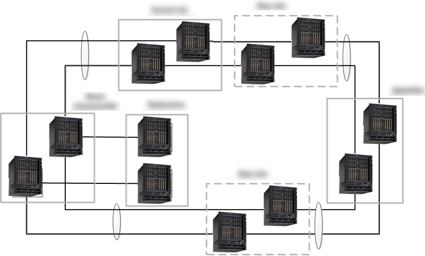
A topological scheme without using DWDM
Thus, a competent statement of the problem (more precisely, an understanding of architecture) made it obvious, for the customer, the question of choosing a technology.
A little more complicated: the choice of equipment node
The question of the choice of equipment and architectural solution of the DWDM network is being solved. Initially, it is not clear what specifically and in what volumes the traffic will be transmitted. Also, the topology of the network was not fully understood (it was developing). Customer requirements sometimes changed over the course of two weeks as new analytical data and new development plans became available. Naturally, to put into the project a system that initially would cover all possible requirements of the customer is insanely expensive.
The customer actively scaled, but could not predict beyond two years. We agreed that the network is being built with nodes that have a reserve in the planning horizon. Further, with increasing traffic, the network could be expanded one and a half times without changing the chassis, without using new technologies and without fundamentally changing the architecture. In total, more than 200 Gb / s of traffic was transferred to the line between the sites.
Architecture - 3 flat rings, 5 multiplexers, linear redundancy. The odd number of multiplexers is explained by the fact that one multiplexer received two lines, and performed the function of 2 devices. This architecture allowed us not to use a cross-switching matrix for organizing redundancy and costing cheaper Optical Line Protectionmodules. At the same time, the system only benefited from such a solution, since no traffic was transmitted through the backplane.
Simply put, we deliberately made the functionality of multiplexers less flexible, but at the same time increased reliability and reduced the cost of nodes. Of course, for an accurate calculation, it was necessary to check hundreds of parameters and recount the project with the engineering team more than a dozen times.
Third example: there is not much reliability
Initially, when building a DWDM system, the main criterion was fault tolerance. It might seem that redundancy is redundant, but it is not. A 1 + 1 full backup system was selected and an additional line backup was laid down. Why was this done? The fact is that with full 1 + 1 redundancy and a break in the optical cable, traffic in one of the systems disappears until the optical cable is restored. With combined redundancy during cable breaks, traffic in one of the systems disappears only for 50 ms or less (in our case), after which a switchover occurs, and both systems operate at full power, which allows the customer to transfer extra traffic through one of the systems. Also, such a system allows you to survive both a single cable break, and the simultaneous failure of any of the nodes in the event of the same fire.
An example of one particularly large bank
We made a bunch for three data centers of the bank and two of our own, where they have a number of critical services. We, in fact, linked two infrastructures - our own infrastructure and the customer’s infrastructure. Communication - optics with DWDM. An optimal set of equipment was searched for that corresponded to a particular topology and to specific tasks. Next, the algorithms for the operation of this network structure were designed and tuned (in fact, rings with two cuts). At each point there is a complete catalog of scenarios for the failure of the sites completely, for each individual node, channel, physical line, and combinations of these factors — a kind of large table of typical reactions. Even the scenario was developed "and if, for example, the multiplexer’s operation fails at the same time and at the same time the line breaks in a completely different area." In theory, this is unlikely but I know at least two cases with the operator and the bank, when this happened with a difference of hours. Murphy's laws in the backbone area work like nowhere else. Well, malicious intent in the scripts was also not excluded.

Here is the project card of another bank, still large, but not so large:
• Equipment of MSTP 15454E Cisco Systems
• Three sites (main data center, backup data center, operator), distance 5-20 km
• Network topology - a full ring
• Client interfaces between Data centers - 10GE - 8 pcs., FC-800 - 8 pcs., FC-400 - 4 pcs., GE - 16 pcs.
• Client interfaces from each data center to the operator site - FE / GE - 8 pcs.
• Protection of the client signal is used - in case of a single ring break, the signal switches to the other direction within 50 ms
• Multiplexers for 40 channels (wavelengths) are
used • Transponder boards are used - the clients are connected with multimode optics or copper
• 220 V power from two power supplies is used
• Data center platforms used 5 chassis of the M6 construct (6 slots for line cards), the operator platform - 2 chassis.
• A typical set of data center equipment occupies 34 RU of rack space
• Work on the deployment and launch of the system was performed by two people within a month
• Optics for the needs of DWDM were allocated in stages as the functionality of the existing network was transferred to the already launched sections of the new transport network
Here is another similar example:

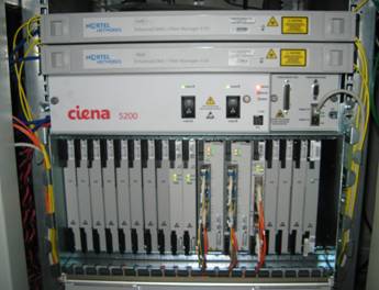
This is how the hardware itself looks:
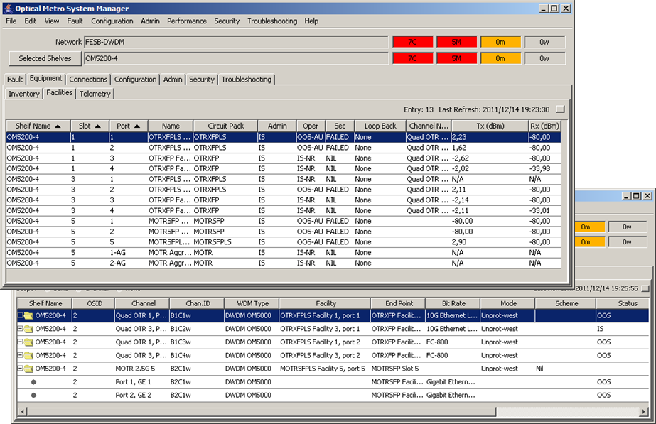
Management interface (one of the options):
Result
As a rule, at the entrance we have a bank or other similar customer with its own optical line, which needs a new data transmission system (more precisely, a deep modernization of the old one). The specifics of such channels in Russia is such that while it works, it’s better not to touch it. Modernization occurs if and only if the customer needs an expansion in terms of speed, and not upon the release of new technologies.
During the project, we are building a reliable DWDM network. DWDM editing offers growth opportunities without replacing optics.
A few general educational tips:
- Most often, power supplies, fans, and client optics fail. You need to keep the parts in a hot reserve and pre-purchase with a margin. We do this, knowing the failure rates for the year.
- Support for power from 220 VAC is very convenient in practice (unless you are a mobile operator).
- DWDM is spectral multiplexing, not traffic compression. We work with the signal at the physical level. There is still optimization at the protocol level and above, it solves other problems - these are the details of the colleagues who are involved in it.
- Protection (Switching / Trunk Switch) can be implemented both at the level of the multiplexed signal (cheap, but not safe), and for each wavelength individually (expensive, but reliable).
- Using custom XFP, SFP + allows you to unify equipment and reduce the cost of spare parts, but it increases the cost of specifications by 1.5-2 times compared with fixed XFP (10 Gigabit Small Form Factor Pluggable), SFP + (Enhanced small form-factor pluggable).
- One of the common problems of modernization is attempts at minor optimization. When the customer himself establishes a system that requires constant adjustments, equipment reinstallation once every six months, etc., a phenomenon arises as in the joke about "the sun rises and sets in." Almost all signalmen were faced with the fact that you just touch the equipment - and now the problems begin to climb out of all the cracks. You can laugh at it as much as you like, but with really shamanistic independent decisions, a bank billing can get up for a day while the team decides what happened. It is unlikely that anyone needs such risks, therefore, the right architecture also implies a clear understanding of how and where the node will be modernized.
Summary
For 9 years, our team has gained very interesting experience working with the former Nortel now - Siena, Tsiska, Huawei, MRV, X-Terra and other vendors. There were also introductions of domestic manufacturers. As a result, an accurate understanding of the specifics of the equipment appeared (I repeat, in the task of the line for the operator, the experts themselves are more abundant in the operators themselves) - but it is precisely in terms of building reliable networks, I think that we know almost all possible rakes. If you are suddenly interested in sorting out some nuance or understanding how to design and calculate correctly, ask in the comments or by mail to AFrolov@croc.ru.
And, taking this opportunity, I convey fiery greetings to all those who dig in the city limits without building permits.