Makeblock Designer Plotter
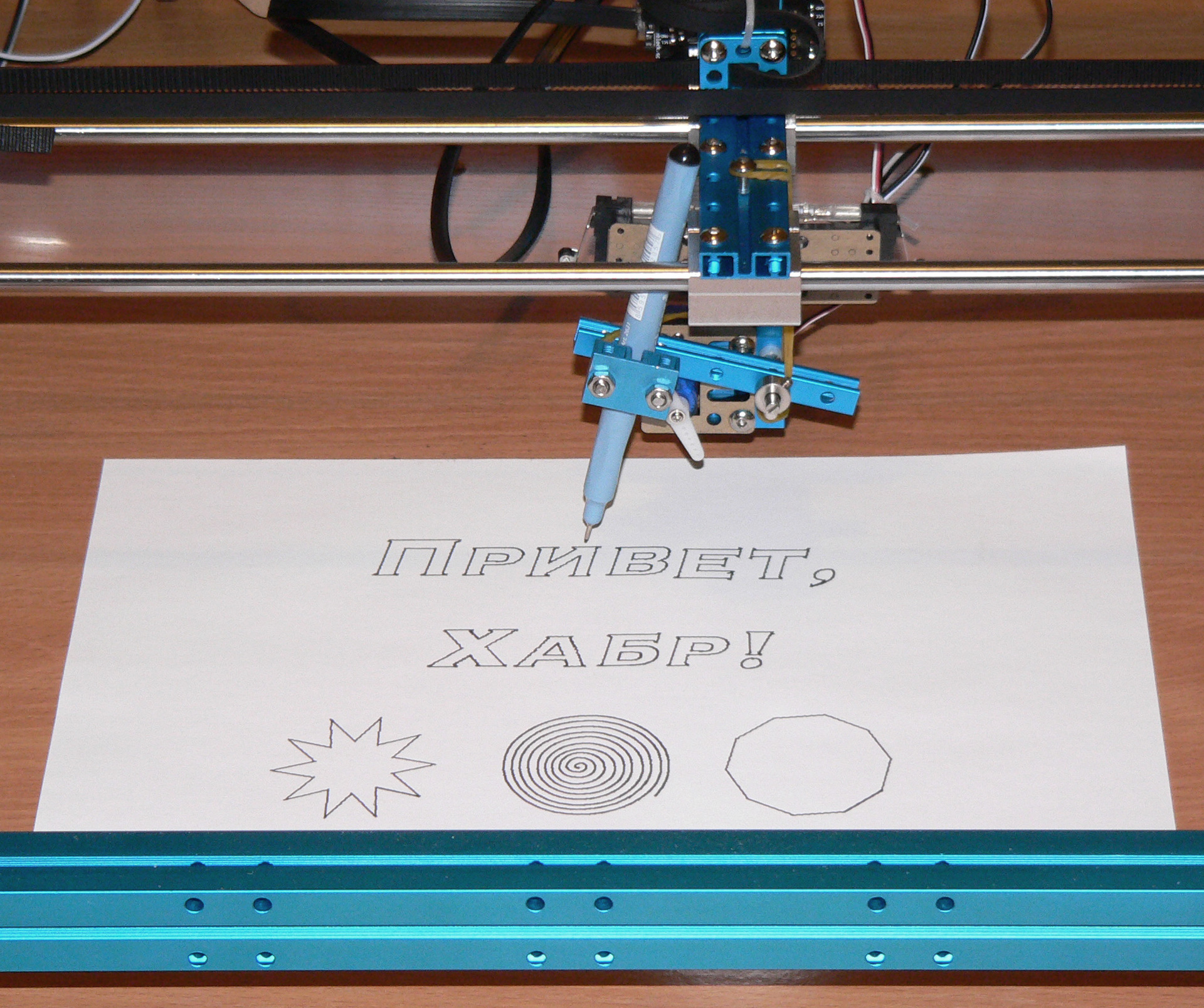
I learned about the Makeblock designer after his kickstart campaign ended . It’s a pity, because there was a chance to buy designer kits at a fairly low price. After a successful campaign, the authors continued to develop their ideas and created a set for the plotter -
The plotter interested me for two reasons: the ability to draw a
Delivery
Delivery Details
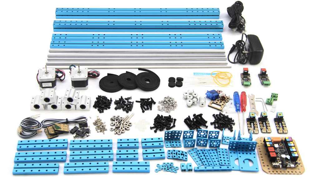
The plotter is sold as a “build it yourself” kit. The weight of the parcel is a few kilograms, so shipping can be expensive. But I found the Chinese Seeed service , which when sent for $ 500 will be sent free of charge via DHL / EMS. In addition to the plotter, I took from them a laser cutter, Raspberry Pi and several shields for Arduino , fitting into the indicated amount and convincing myself that in the future all this will be useful to me.
The parcel arrived approximately two weeks after placing the order in the form of a heavy cardboard box tightly packed with details. Everything inside is in good condition, every detail is wrapped in some kind, but on one of the supporting frame structures I found an unpleasant dent, which, however, did not affect the functionality of the part.
The parcel arrived approximately two weeks after placing the order in the form of a heavy cardboard box tightly packed with details. Everything inside is in good condition, every detail is wrapped in some kind, but on one of the supporting frame structures I found an unpleasant dent, which, however, did not affect the functionality of the part.
Assembly
It took me at least 10 hours to assemble the plotter. The assembly plan is contained in a PDF document , where, step by step, the plotter takes on its form. For all the details of the instructions, sometimes it was necessary to disassemble and reassemble the individual blocks when it came to understanding their function. I recommend to run a few pages ahead when assembling.
Build problems
The holes in the aluminum parts of the designer are offset within a millimeter from their intended position, which led to problems in those places where the parts were assembled end to end. I found two such places: right at the first step, when the screws holding the frame abut against each other; and when attaching the stepper motor controller board, which could not get along with the plotter leg. I managed to solve all this, but I wouldn’t count on the accuracy of the shape of my parts in place of the authors of the designer.
Once stuck a screw in the sleeve. The fact is that the bushings are attached to the axis with small set screws without a hat. At the initial stage of assembly, it was not indicated that then these bushings must be shifted and aligned somewhere, so I tightened them well. Later it turned out that the screw was stuck - the screwdriver skidded and did not want to unscrew. By the way, the material of the supplied tools is the cheapest, metal is soft. I considered several solutions, from buying new parts to pulling a screw by screwing an even smaller left-hand screw. The provisions were saved by a screwdriver made of harder steel.
Once stuck a screw in the sleeve. The fact is that the bushings are attached to the axis with small set screws without a hat. At the initial stage of assembly, it was not indicated that then these bushings must be shifted and aligned somewhere, so I tightened them well. Later it turned out that the screw was stuck - the screwdriver skidded and did not want to unscrew. By the way, the material of the supplied tools is the cheapest, metal is soft. I considered several solutions, from buying new parts to pulling a screw by screwing an even smaller left-hand screw. The provisions were saved by a screwdriver made of harder steel.
Short video about plotter assembly (from the Internet)
Mechanics
XY Travel Principle
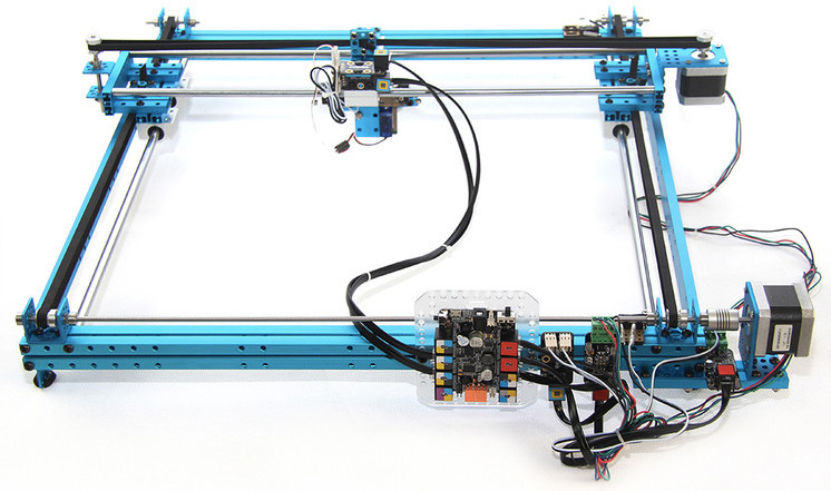
The working part of the plotter is a platform with a pencil, sliding along the guide axes. To understand how this platform moves, take another look at the photo above.
There are two stepper motors, one for each axis of movement. Using transmission belts, fixed by the ends on the platform, the rotation of the engine axis is converted into linear motion of the platform along the "rail".
There are two stepper motors, one for each axis of movement. Using transmission belts, fixed by the ends on the platform, the rotation of the engine axis is converted into linear motion of the platform along the "rail".
The principle of lowering and raising the pencil
The principle of lowering and raising the pencil, I understood only at the end of the assembly: The
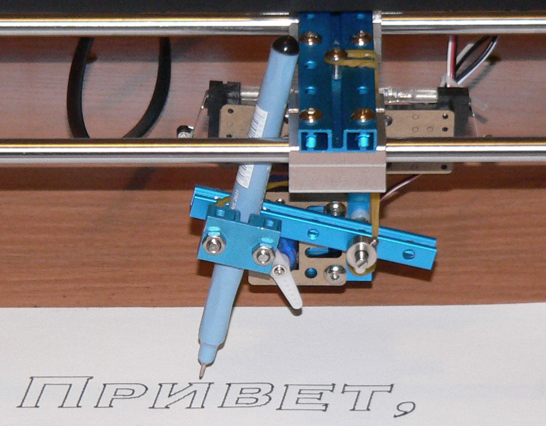
pencil is rigidly attached to the bar, and the bar is mounted on the axis. The bar is divided by an axis into two shoulders - on one pencil, and on the other an elastic band is attached so that the bar presses the pencil on the paper. The “blade” of the servo-driver has two working positions: vertical, in which the “blade” raises the bar, preventing it from pressing the pencil to the paper, and horizontal, in which the “blade” does not prevent the bar from pressing the pencil to the paper.
Along the axis of the mounting strap there is a backlash, which leads to a "jitter" of the lines. I managed to remove it by adding an elastic band, pressing the bar to the platform.
pencil is rigidly attached to the bar, and the bar is mounted on the axis. The bar is divided by an axis into two shoulders - on one pencil, and on the other an elastic band is attached so that the bar presses the pencil on the paper. The “blade” of the servo-driver has two working positions: vertical, in which the “blade” raises the bar, preventing it from pressing the pencil to the paper, and horizontal, in which the “blade” does not prevent the bar from pressing the pencil to the paper.
Along the axis of the mounting strap there is a backlash, which leads to a "jitter" of the lines. I managed to remove it by adding an elastic band, pressing the bar to the platform.
Electronics
Electronic units and their connection
The control component of the plotter is a board based on the Arduino Leonardo . Its feature is built-in support for USB connection to a computer. If Arduino is usually reset when establishing a new serial connection to the computer, then Arduino Leonardo retains its current state, which means that you can connect to the plotter as many times as you like, saving all the settings (first of all, zero in XY).
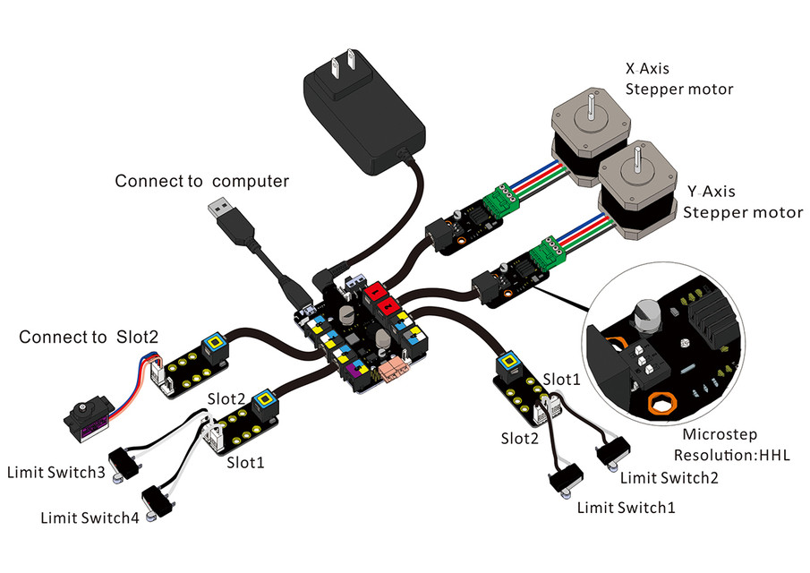
The board has 8 RJ25 ports through which the controllers of two stepper motors, a servo drive and four switches are connected in case the platform rests on the frame. Power for stepper motors is supplied separately through the supplied power supply with an American plug.
The board has 8 RJ25 ports through which the controllers of two stepper motors, a servo drive and four switches are connected in case the platform rests on the frame. Power for stepper motors is supplied separately through the supplied power supply with an American plug.
Search for optimal microstep engines
During the writing of this article, I unexpectedly discovered that the plotter requires the adjustment of two parameters of stepper motor controllers: the number of microsteps per step and the current that determines the torque. Read more about setting these parameters here , but not a word about this in the instructions!
In theory, an increase in the number of microsteps improves the smoothness of lines and reduces noise, but also significantly reduces the torque of the engines. I tried to compare the quality of the resulting image depending on the number of microsteps:
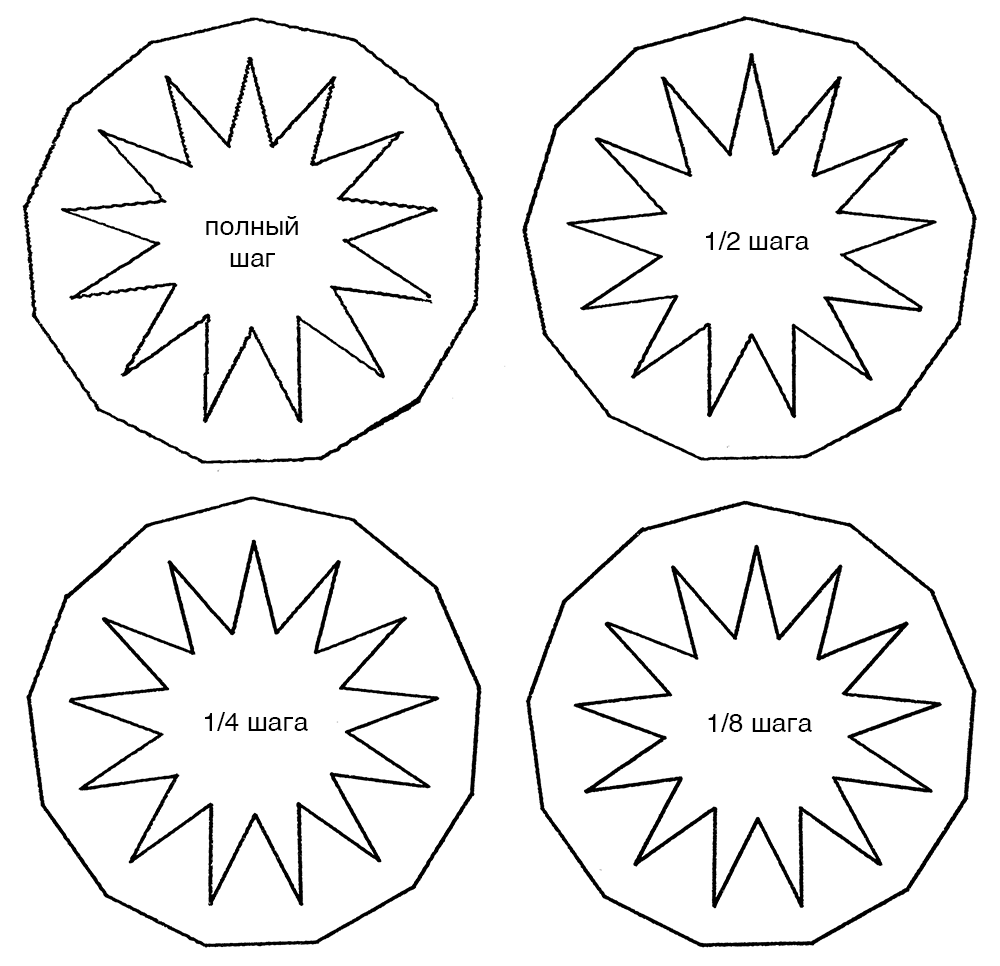
As you can see from this picture, the best quality gives 1/8 and 1/4 steps. Further, it turned out that with a resolution of 1/8 step, one of the engines starts to slip and “lose” microsteps due to lack of torque. Increasing the current to maximum only slightly improved the situation, so the 1/4 step mode came out the winner. By the way, in microstep mode the engine is much less noisy!
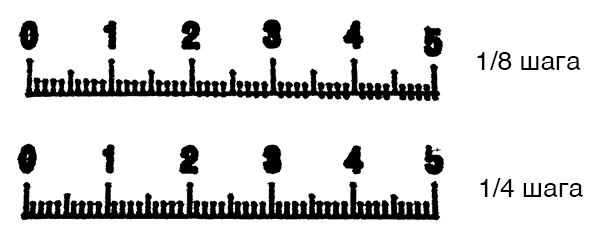
In theory, an increase in the number of microsteps improves the smoothness of lines and reduces noise, but also significantly reduces the torque of the engines. I tried to compare the quality of the resulting image depending on the number of microsteps:
As you can see from this picture, the best quality gives 1/8 and 1/4 steps. Further, it turned out that with a resolution of 1/8 step, one of the engines starts to slip and “lose” microsteps due to lack of torque. Increasing the current to maximum only slightly improved the situation, so the 1/4 step mode came out the winner. By the way, in microstep mode the engine is much less noisy!
Control
At the end of the assembly, the plotter control board must be programmed. The program implements the translation of the so-called G-code , in which the pencil movement commands are written in text form.
There are many editors for converting a vector image into G-code, but the authors recommend using the cross-platform and free Inkscape editor with the installed plug-in for generating G-code Gcodetools .
To send the plotter a G-code for execution, you need to connect to its control board via a USB cable and open a serial connection. For Windows it will be some kind of COM3 or COM4 port, for MacOS it will be something like /dev/tty.usbmodem1421
User interface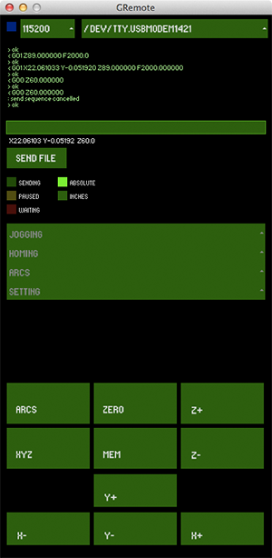 The designer’s authors wrote a Java program that opens a connection to the device and allows you to control the pencil using the arrow keys, set the position to zero, set the axis resolution and send the G-code written in the file.
The program was originally designed for Windows, but after loading the desired library, it launches under MacOS.
I found that sometimes the connection to the plotter freezes, so I wrote a Python script for this case, which sends G-code directly through a serial connection. In this case, I use the Java program to set the starting point, then I run the script.
The designer’s authors wrote a Java program that opens a connection to the device and allows you to control the pencil using the arrow keys, set the position to zero, set the axis resolution and send the G-code written in the file. The program was originally designed for Windows, but after loading the desired library, it launches under MacOS.
I found that sometimes the connection to the plotter freezes, so I wrote a Python script for this case, which sends G-code directly through a serial connection. In this case, I use the Java program to set the starting point, then I run the script.
Python script
###############################################################################
import serial, re, time
import sys, argparse
SERIAL = "/dev/tty.usbmodem1421"
parser = argparse.ArgumentParser(description = "G-code file sender")
parser.add_argument("--input",  help = "file to send", required = True)
args = vars(parser.parse_args())
###############################################################################
def send(stream, command):
    if command[-1] != "\n": command += "\n"
    sys.stdout.write("<= " + command)
    stream.write(command)
    while True:
        s = stream.readline()
        sys.stdout.write("=> " + s)
        if s[0] != "#": break
fin = open(args["input"])
stream = serial.Serial(SERIAL, 115200)
send(stream, "$1 X8 Y12 Z21")
send(stream, "$2 X11 Y13 Z9")
send(stream, "$3 X22 Y19 Z22")
send(stream, "$4 X23 Y18 Z23")
send(stream, "$6 X88.0 Y88.0 Z40.0") # set axis resolution
send(stream, "G90")
send(stream, "G21")
for s in fin:
    s = re.sub(r"\([^)]*\)", r"", s)
    if s.strip(): send(stream, s.strip())
fin.close()
###############################################################################
Program modification
The program for the control board of the plotter perceives X, Y and Z as three axes, the movement along which is specified in millimeters. But the fact is that the Z axis is actually set by the angle of rotation of the servo! In my case, 90 degrees means a lowered pencil, 60 degrees - raised. As a result, raising and lowering the pencil takes, from the point of view of the program, as much time as drawing a line in (90 - 60) => 30 mm! The pencil goes down and waits, then draws a line, then rises and waits. Not only does the image take longer (as if 30 mm is added to each continuous path), but standing idle with a marker or liner on paper adds thick dots at the beginning of the path. The program had to be modified by compressing the distances along the Z axis:
long calculate_feedrate_delay(float feedrate)
{
    //how long is our line length?
    float distance = sqrt(delta_units.x*delta_units.x + delta_units.y*delta_units.y + delta_units.z*delta_units.z / 100.f);
    ...
}
Result
When I was about to start the plotter to draw some visual pictures for this article, a serious malfunction was discovered: the lines of the drawing stopped converging with each other. It turned out that linear bearings scratched the furrows on the guide axles and began to slip from time to time. I suspected that the axles should be lubricated, but doubted, because there was not a word in the instructions about this. So, the plotter now requires repair and lubrication.
Grease selection and repair
Judging by this article, the best lubricant is oil-suspended Teflon. It is produced in the United States under the brand name Super Lube . In second place are synthetic gear oils (automobile?). Until Teflon grease arrived, I tried domestic engine oil, but it didn’t help much.
I ordered replacement bearings on eBay for $ 2.55 apiece, a total of six. The guide axes turned out to be much more expensive, because they were made by special order, but I decided not to change them, but crank them to move the furrows from the bearing paths.
I ordered replacement bearings on eBay for $ 2.55 apiece, a total of six. The guide axes turned out to be much more expensive, because they were made by special order, but I decided not to change them, but crank them to move the furrows from the bearing paths.
The problem with slipping gave me the idea of controlling missed engine steps with a laser mouse. Judging by the articles found , this would be a very effective and beautiful way to solve the exact positioning of stepper motors.
Finishing the article, I still take the risk and draw a few drawings in a less accurate 1/2 step mode, without waiting for the components and lubrication. Images were taken with a liner with a line width of 0.3 mm