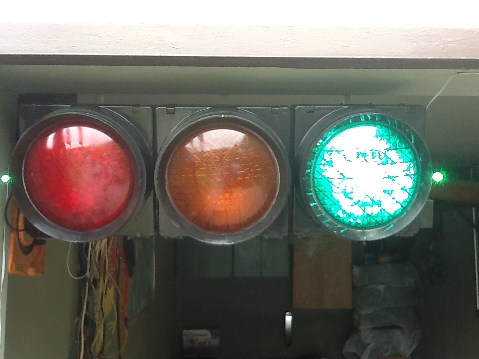
Traffic light in the garage. Present
It was drizzling and nasty. The mood was vile.
He was lying on the side of the road and quietly rusting. Nearby on a pillar a young fellow sparkled with lights.
I stopped and put it in the trunk.
I am no longer alone.
And he is not alone.
He brought it to the country, dismantled it, washed it from dirt and painted it from a spray can.
The application was found immediately. The new car turned out to be wider than the previous one and parking in the garage became more problematic. All sorts of “bells on the strings” are not for us. So - stationary parking sensors.
1. Widespread ultrasonic sensors HC-SR04. 2 pieces, one for each wall. The Internet is full of information about them. Description below.
Ultrasonic Ranging Module HC - SR04
Ultrasonic ranging module HC - SR04 provides 2cm - 400cm non-contact measurement function, the ranging accuracy can reach to 3mm. The modules includes ultrasonic transmitters, receiver and control circuit. The basic principle of work:
Using IO trigger for at least 10us high level signal.
The Module automatically sends eight 40 kHz and detect whether there is a pulse signal back.
IF the signal back, through high level, time of high output IO duration is the time from sending ultrasonic to returning.
Test distance = (high level time × velocity of sound (340M / S) / 2
5V Supply
Trigger Pulse Input
Echo Pulse Output
0V Ground
Working Voltage DC 5 V
Working Current 15mA
Working Frequency 40Hz
Max Range 4m
Min Range 2cm
Measuring Angle 15 degree
Trigger Input Signal 10uS TTL pulse
Echo Output Signal Input TTL lever signal and the range in proportion
Dimension 45 * 20 * 15mm

The Timing diagram is shown below. You only need to supply a short 10uS pulse to the trigger input to start the ranging, and then the module will send out an 8 cycle burst of ultrasound at 40 kHz and raise its echo. The Echo is a distance object that is pulse width and the range in proportion. You can calculate the range through the time interval between sending trigger signal and receiving echo signal. Formula: uS / 58 = centimeters or uS / 148 = inch; or: the range = high-level time * velocity (340M / S) / 2; we suggest to use over 60ms measurement cycle, in order to prevent trigger signal to the echo signal.
Fastened to the side walls at the entrance to the garage using galvanized sheet strips. The mount should allow you to adjust the sensors "in place" depending on the size of the car (height, hood width, wing shape ...).
2. The controller is PIC16f84a. Why this one:
a) I have them;
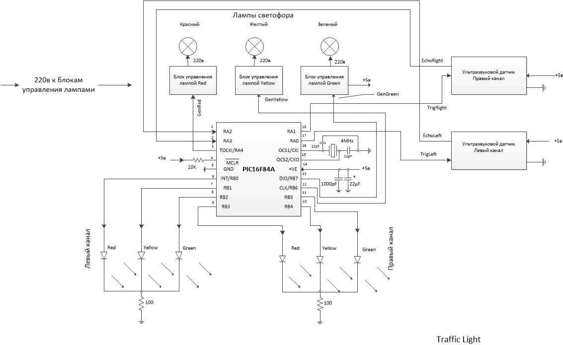
b) it has 2 I / O ports, a total of 13 bits, just as much as necessary. 3 pcs. - traffic light control (Red - Yellow - Green), 6pcs. - left and right LEDs (K-Zh-Z), 2pcs. - location pulse (Trig) on the left and right sensors, 2pcs. - reflected pulse (Echo) from the left and right sensors.
3. Two three-color LEDs, one for each wall. LEDs Red - Yellow - Green not found. Maybe they do not exist, but maybe I was looking badly. Therefore, the role of yellow in LEDs is played by blue. For complete identity, of course, separate LEDs could be used. And there would be no yellow problems. But I considered such a compromise acceptable.
4. Traffic light control units. 3pcs., One for each lamp.
The control unit for turning on / off the TV is ideal.
It consists of a low-power power transformer (220 to 7 volts), a diode rectifier, a stabilizer on KP142EN5x (or an analog), a transistor switch and a relay. When a logical “1” is applied to the input, the key is opened, the relay is activated and 220v is output. In addition, since KREN provides stabilized 5v, it is reasonable to power the microcontroller from one of these units. They are full on any radio market. If someone annoys the clicking of a relay, it is easy to make a thyristor circuit.
5. Quartz resonator at 4 MHz.
This is a very convenient frequency for those microcontrollers that I have. Easy to read time parameters. The period of clock pulses = 250ns, the machine cycle consists of four clock cycles, therefore, equal to 1 µs. Commands in RISC controllers are executed in 1 or 2 machine cycles, so there is no problem calculating the time that elapses "from how ... to before". You can use another within the permissible frequencies, but you will have to recount the timeouts. This is a very small problem.
6. Several resistors and capacitors recommended by the typical PIC16f84a switching circuit and two current-limiting resistors for LEDs. For example, look here: link .
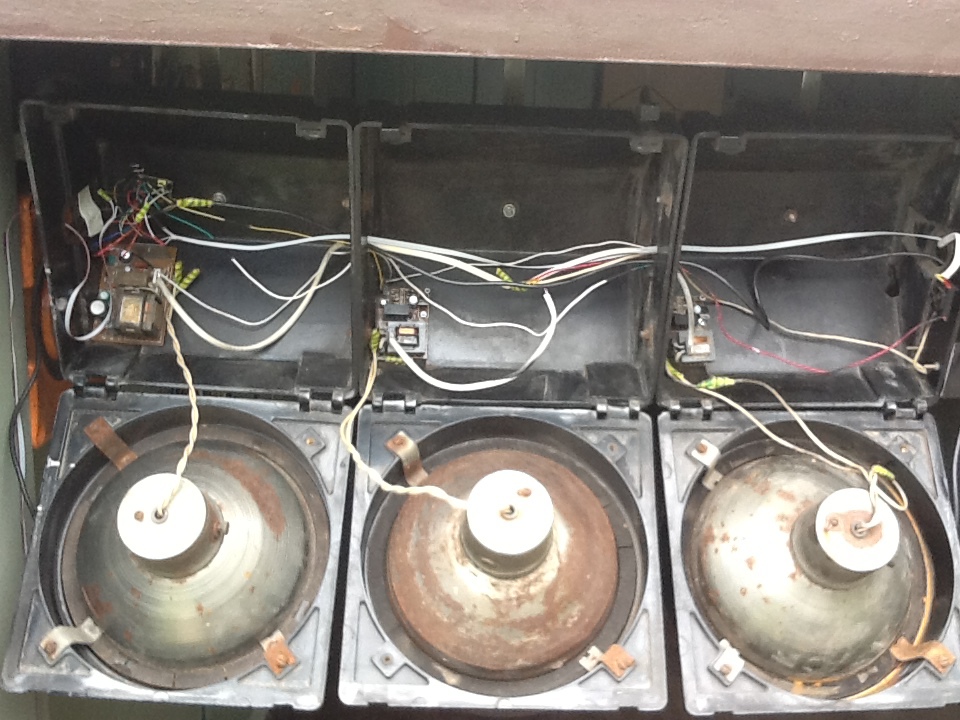
General view of the assembled device:
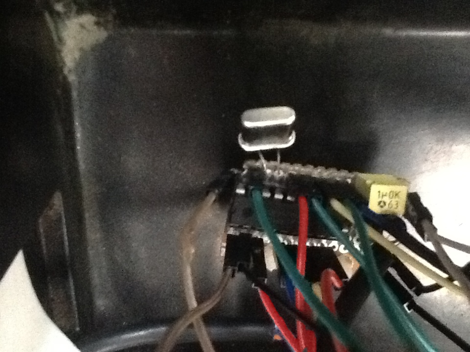
Board with a microcontroller:
Simple, almost linear. On power-up, a hardware test is performed. Allegedly a test, more for beauty. At intervals of 1 second, red-yellow-green are switched, then at the same interval all the traffic lights turn on three times. After that - the transition to an endless cycle of polling the left and right channels. When each channel passes, depending on the result, the corresponding PORTB bit (flag) is set and one of the LEDs for this channel is turned on. At the end of the full cycle, the state of the Red-Yellow-Green flags of both channels is analyzed and, based on this, the corresponding traffic light is switched on. The truth table looks like this:
Any channel is Red . Traffic Light - Red .
Both channels Green. Traffic Light - Green .
All other cases. Traffic Light - Yellow .
In a few words, the core of the algorithm "in steps":
1. We form the impulse Trig;
2. We expect the arrival of a response pulse Echo;
3. Run the timeout 1ms;
4. After the timeout expires, we check to see if there is another “log.1” at the input of Echo;
5. If not, then we are at a dangerous approximation to the sensor of the corresponding channel. Turn on the red flag of this channel and go to another channel;
6. If Echo is still there, repeat steps 3 and 4;
7. If not, then we are at an average distance from the sensor. Turn on the yellow flag and go to another channel;
8. If Echo is still there, then we are far away. We are waiting for its end, turn on the green flag and go to another channel.

What is the point? We do not need to calculate the exact distance to the object. That is, it is not necessary to divide the pulse width of Echo by 58, as indicated in the description of the sensor. We are not building a rangefinder. We only need to know the position of the object with respect to two identical ranges of distances from the object to the sensor. For this, a 1ms timeout is used (see clause 3), which ultimately gives: 1000µs: 58 = 17cm. So - closer than 17cm - red, from 17 to 34cm - yellow, then 34cm - green. By changing the constants in the “Pause 1ms” subroutine, you can vary the distance depending on the size of the car, the width of the gate and driving skills.
The firmware listing is below. Assembler. Constants, except for those in timeouts, are in the binary system, since the device is bit-oriented. And when debugging or analyzing, you would still have to translate it into a binary system. The program uses Watchdog Timer to prevent freezes.
The author expresses gratitude to his wife, who during real trials fearlessly stood at the garage door and ensured that the author did not drive either the left or right wing of the car into the wall at the entrance. If there are fearless followers who want to repeat the project, the author will answer everyone.
He was lying on the side of the road and quietly rusting. Nearby on a pillar a young fellow sparkled with lights.
I stopped and put it in the trunk.
I am no longer alone.
And he is not alone.
He brought it to the country, dismantled it, washed it from dirt and painted it from a spray can.
The application was found immediately. The new car turned out to be wider than the previous one and parking in the garage became more problematic. All sorts of “bells on the strings” are not for us. So - stationary parking sensors.
Equipment
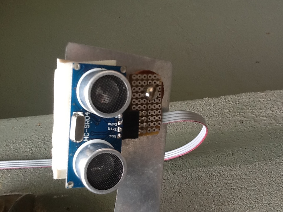
1. Widespread ultrasonic sensors HC-SR04. 2 pieces, one for each wall. The Internet is full of information about them. Description below.
Ultrasonic Ranging Module HC - SR04
Product features:
Ultrasonic ranging module HC - SR04 provides 2cm - 400cm non-contact measurement function, the ranging accuracy can reach to 3mm. The modules includes ultrasonic transmitters, receiver and control circuit. The basic principle of work:
Using IO trigger for at least 10us high level signal.
The Module automatically sends eight 40 kHz and detect whether there is a pulse signal back.
IF the signal back, through high level, time of high output IO duration is the time from sending ultrasonic to returning.
Test distance = (high level time × velocity of sound (340M / S) / 2
Wire connecting direct as following:
5V Supply
Trigger Pulse Input
Echo Pulse Output
0V Ground
Electric parameter
Working Voltage DC 5 V
Working Current 15mA
Working Frequency 40Hz
Max Range 4m
Min Range 2cm
Measuring Angle 15 degree
Trigger Input Signal 10uS TTL pulse
Echo Output Signal Input TTL lever signal and the range in proportion
Dimension 45 * 20 * 15mm
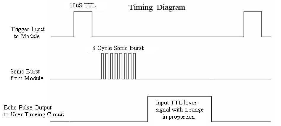
Timing diagram
The Timing diagram is shown below. You only need to supply a short 10uS pulse to the trigger input to start the ranging, and then the module will send out an 8 cycle burst of ultrasound at 40 kHz and raise its echo. The Echo is a distance object that is pulse width and the range in proportion. You can calculate the range through the time interval between sending trigger signal and receiving echo signal. Formula: uS / 58 = centimeters or uS / 148 = inch; or: the range = high-level time * velocity (340M / S) / 2; we suggest to use over 60ms measurement cycle, in order to prevent trigger signal to the echo signal.
Fastened to the side walls at the entrance to the garage using galvanized sheet strips. The mount should allow you to adjust the sensors "in place" depending on the size of the car (height, hood width, wing shape ...).
2. The controller is PIC16f84a. Why this one:
a) I have them;
b) it has 2 I / O ports, a total of 13 bits, just as much as necessary. 3 pcs. - traffic light control (Red - Yellow - Green), 6pcs. - left and right LEDs (K-Zh-Z), 2pcs. - location pulse (Trig) on the left and right sensors, 2pcs. - reflected pulse (Echo) from the left and right sensors.
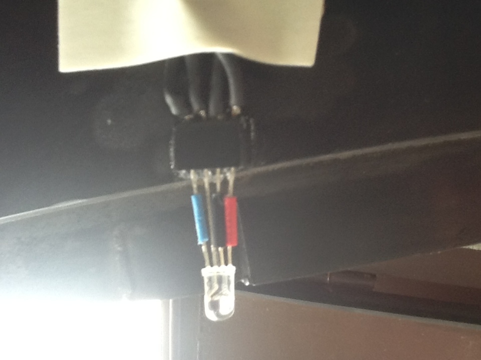
3. Two three-color LEDs, one for each wall. LEDs Red - Yellow - Green not found. Maybe they do not exist, but maybe I was looking badly. Therefore, the role of yellow in LEDs is played by blue. For complete identity, of course, separate LEDs could be used. And there would be no yellow problems. But I considered such a compromise acceptable.
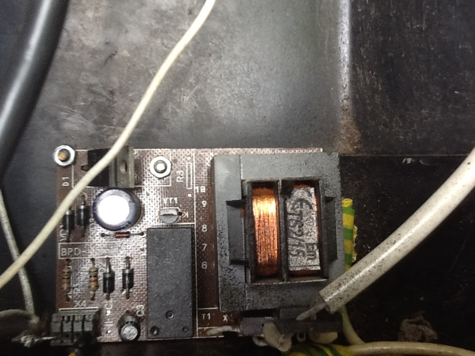
4. Traffic light control units. 3pcs., One for each lamp.
The control unit for turning on / off the TV is ideal.
It consists of a low-power power transformer (220 to 7 volts), a diode rectifier, a stabilizer on KP142EN5x (or an analog), a transistor switch and a relay. When a logical “1” is applied to the input, the key is opened, the relay is activated and 220v is output. In addition, since KREN provides stabilized 5v, it is reasonable to power the microcontroller from one of these units. They are full on any radio market. If someone annoys the clicking of a relay, it is easy to make a thyristor circuit.
5. Quartz resonator at 4 MHz.
This is a very convenient frequency for those microcontrollers that I have. Easy to read time parameters. The period of clock pulses = 250ns, the machine cycle consists of four clock cycles, therefore, equal to 1 µs. Commands in RISC controllers are executed in 1 or 2 machine cycles, so there is no problem calculating the time that elapses "from how ... to before". You can use another within the permissible frequencies, but you will have to recount the timeouts. This is a very small problem.
6. Several resistors and capacitors recommended by the typical PIC16f84a switching circuit and two current-limiting resistors for LEDs. For example, look here: link .
General view of the assembled device:
Board with a microcontroller:
Circuit diagram
Algorithm
Simple, almost linear. On power-up, a hardware test is performed. Allegedly a test, more for beauty. At intervals of 1 second, red-yellow-green are switched, then at the same interval all the traffic lights turn on three times. After that - the transition to an endless cycle of polling the left and right channels. When each channel passes, depending on the result, the corresponding PORTB bit (flag) is set and one of the LEDs for this channel is turned on. At the end of the full cycle, the state of the Red-Yellow-Green flags of both channels is analyzed and, based on this, the corresponding traffic light is switched on. The truth table looks like this:
Any channel is Red . Traffic Light - Red .
Both channels Green. Traffic Light - Green .
All other cases. Traffic Light - Yellow .
In a few words, the core of the algorithm "in steps":
1. We form the impulse Trig;
2. We expect the arrival of a response pulse Echo;
3. Run the timeout 1ms;
4. After the timeout expires, we check to see if there is another “log.1” at the input of Echo;
5. If not, then we are at a dangerous approximation to the sensor of the corresponding channel. Turn on the red flag of this channel and go to another channel;
6. If Echo is still there, repeat steps 3 and 4;
7. If not, then we are at an average distance from the sensor. Turn on the yellow flag and go to another channel;
8. If Echo is still there, then we are far away. We are waiting for its end, turn on the green flag and go to another channel.
What is the point? We do not need to calculate the exact distance to the object. That is, it is not necessary to divide the pulse width of Echo by 58, as indicated in the description of the sensor. We are not building a rangefinder. We only need to know the position of the object with respect to two identical ranges of distances from the object to the sensor. For this, a 1ms timeout is used (see clause 3), which ultimately gives: 1000µs: 58 = 17cm. So - closer than 17cm - red, from 17 to 34cm - yellow, then 34cm - green. By changing the constants in the “Pause 1ms” subroutine, you can vary the distance depending on the size of the car, the width of the gate and driving skills.
Firmware
The firmware listing is below. Assembler. Constants, except for those in timeouts, are in the binary system, since the device is bit-oriented. And when debugging or analyzing, you would still have to translate it into a binary system. The program uses Watchdog Timer to prevent freezes.
Listing
	list      p=16F84A            ; list directive to define processor
	#include         ; processor specific variable definitions
	__CONFIG   _CP_OFF & _WDT_ON & _PWRTE_ON & _XT_OSC
;********************** Contact Assignment *****************************
;	Contact #	Name		Function
; 	17		RA0		output 	TrigLeft
; 	18		RA1		output 	TrigRight
;	01		RA2		input	EchoLeft
;	02		RA3		input	EchoRight
;	03		RA4		output	GenRed
;	06		RB0		output	RedLeft
;	07		RB1		output	YellowLeft
;	08		RB2		output	GreenLeft
;	09		RB3		output	RedRight
;	10		RB4		output	YellowRight
;	11		RB5		output	GreenRight
;	12		RB6		output	GenYellow
;	13		RB7		output	GenGreen
;
;******************* Constants **************************
;	Red	00000001	Left channel
;	Yellow	00000010	Left channel
;	Green	00000100	Left channel
;
;	Red	00001000	Right channel
;	Yellow	00010000	Right channel
;	Green	00100000	Right channel
;***** VARIABLE DEFINITIONS *****************************
		CBLOCK		0x0C
Reg_1					; 0x0C use within Pause subroutine
Reg_2					; 0x0D use within Pause subroutine
Reg_3					; 0x0E use within Pause subroutine
		ENDC
#define	bank0		bcf	STATUS,RP0	; set bank0
#define bank1		bsf	STATUS,RP0	; set bank1
#define TrigLeft_1	bsf	PORTA,0		; set Trigleft
#define TrigLeft_0	bcf	PORTA,0		; clean Trigleft
#define TrigRight_1	bsf	PORTA,1		; set Trigright
#define TrigRight_0	bcf	PORTA,1		; clean Trigright
#define	EchoLeft	PORTA,2
#define	EchoRight	PORTA,3
#define RedLeft		b'00000001
#define YellowLeft	b'00000010
#define GreenLeft	b'00000100
#define RedRight	b'00001000
#define YellowRight	b'00010000
#define GreenRight	b'00100000
;**********************************************************************
		ORG     0x000             ; processor reset vector
		goto    main              ; go to beginning of program
;----------------------------------------------------------------------
;------------------ SUBROUTINE Pulse --------
;delay = 10 machine cycles = 10 µs
Pulse	    movlw       .3
            movwf       Reg_1
wr0         decfsz      Reg_1,F
            goto        wr0
		return
;------------------ SUBROUTINE Pause 1ms --------
;delay = 1'000 machine cycles
Pause       movlw       .75
            movwf       Reg_1
            movlw       .3
            movwf       Reg_2
wr1         decfsz      Reg_1,F
            goto        wr1
            clrwdt
            decfsz      Reg_2,F
            goto        wr1
            nop
		return
;-------------------- SUBROUTINE Pause 1sec ---
;delay = 1'000'000 machine cycles
Pause1      movlw       .254
            movwf       Reg_1
            movlw       .17
            movwf       Reg_2
            movlw       .6
            movwf       Reg_3
wr2         decfsz      Reg_1,F
            goto        wr2
            clrwdt
            decfsz      Reg_2,F
            goto        wr2
            decfsz      Reg_3,F
            goto        wr2
            nop
            nop
	    	return
;-------------------- SUBROUTINE Pause 50ms --------
;delay = 50'000 machine cycles
Pause2      movlw       .216
            movwf       Reg_1
            movlw       .65
            movwf       Reg_2
wr3         decfsz      Reg_1,F
            goto        wr3
            clrwdt
            decfsz      Reg_2,F
            goto        wr3
            return
;--------------------- SUBROUTINE General Red ---------------
GenRed		bsf	PORTA,4
		bcf	PORTB,6
		bcf	PORTB,7
		return
;--------------------- SUBROUTINE General Green -------------
GenGreen	bsf	PORTB,7
		bcf	PORTA,4
		bcf	PORTB,6
		return
;--------------------- SUBROUTINE General Yellow ------------
GenYellow	bsf	PORTB,6
		bcf	PORTA,4
		bcf	PORTB,7
		return
;--------------------- SUBROUTINE General All ------------
GenAll		bsf	PORTA,4
		bsf	PORTB,6
		bsf	PORTB,7
		return
;---------------------------------------------------------
main
		bank1			; set Bank 1
		movlw	0x00
		movwf	TRISB		; PORTB - out
		movlw	b'00001100
		movwf	TRISA		; RA2,RA3 - input; RA0,RA1,RA4 - output
		bank0			; return to Bank 0
		clrf	PORTA
		clrf	PORTB		; turn off all lights
;---------------------- TEST -----------------------------
		call	GenRed
		call	Pause1
		call	GenYellow
		call	Pause1
		call	GenGreen
		call	Pause1
		bcf	PORTA,4
		bcf	PORTB,6
		bcf	PORTB,7
		call	Pause1
		call	GenAll
		call	Pause1
		bcf	PORTA,4
		bcf	PORTB,6
		bcf	PORTB,7
		call	Pause1
		call	GenAll
		call	Pause1
		bcf	PORTA,4
		bcf	PORTB,6
		bcf	PORTB,7
		call	Pause1
		call	GenAll
		call	Pause1
		bcf	PORTA,4
		bcf	PORTB,6
		bcf	PORTB,7
		call	Pause1
		goto SoundRight
;------------------LEFT----------------------
SoundLeft	TrigLeft_1
		call Pulse
		TrigLeft_0
		btfss EchoLeft
		goto $-1
		call	Pause
		btfss	EchoLeft
		goto SetRedLeft
		call Pause
		btfss EchoLeft
		goto SetYellowLeft
		goto SetGreenLeft
SetRedLeft	movlw RedLeft
		iorwf PORTB,1
		bcf PORTB,1
		bcf PORTB,2
		goto SoundRight
SetYellowLeft	movlw YellowLeft
		iorwf PORTB,1
		bcf PORTB,0
		bcf PORTB,2
		goto SoundRight
SetGreenLeft	movlw GreenLeft
		iorwf PORTB,1
		bcf PORTB,0
		bcf PORTB,1
		clrwdt
		btfsc EchoLeft	; wait Echo end
		goto $-2
		goto SoundRight
;----------------RIGHT---------------------
SoundRight	call Pause2
		TrigRight_1
		call Pulse
		TrigRight_0
		btfss EchoRight
		goto $-1
		call	Pause
		btfss	EchoRight
		goto SetRedRight
		call Pause
		btfss EchoRight
		goto SetYellowRight
		goto SetGreenRight
SetRedRight	movlw RedRight
		iorwf PORTB,1
		bcf PORTB,4
		bcf PORTB,5
		goto SetGenLight
SetYellowRight	movlw YellowRight
		iorwf PORTB,1
		bcf PORTB,3
		bcf PORTB,5
		goto SetGenLight
SetGreenRight	movlw GreenRight
		iorwf PORTB,1
		bcf PORTB,3
		bcf PORTB,4
		clrwdt
		btfsc EchoRight	; wait Echo end
		goto $-2
;------------------------ Set General Lights ----------------
SetGenLight	btfss	PORTB,0		; check RedLeft
		goto 	CheckRedRight
		call	GenRed
		goto	SoundLeft
CheckRedRight	btfss	PORTB,3
		goto	CheckGreenLeft
		call	GenRed
		goto	SoundLeft
CheckGreenLeft	btfss	PORTB,2
		goto	SetGenYellow
		btfss	PORTB,5
		goto	SetGenYellow
		call	GenGreen
		goto	SoundLeft
SetGenYellow	call	GenYellow
		goto	SoundLeft
			END
Video
Acknowledgments and Obligations
The author expresses gratitude to his wife, who during real trials fearlessly stood at the garage door and ensured that the author did not drive either the left or right wing of the car into the wall at the entrance. If there are fearless followers who want to repeat the project, the author will answer everyone.