Blue pill (blue tablet) STM32F103 as a PLC
Introduction
Surely everyone who once started or is just beginning to study STM32 microcontrollers has a Chinese-made debugging motherboard, aptly called Blue Pill by foreign tourists (blue pill).
This motherboard is based on the STM32F103C8T6 chip, which is a 32-bit processor based on the Cortex-M3 core. The picture below shows the classic board and pin assignment.
The appearance of the classic board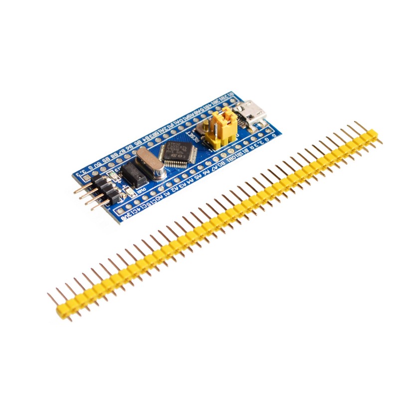
Pin assignment
How in 5 minutes to make a PLC out of available tools?
As often happens, the lessons from the Internet taught us to work with timers, USART, to switch the output states, and even with DMA it turned out to work! And after all the tests, the board safely takes its place on the shelf of spare parts - a good thing, but so far there has been no worthy use.
If you are reading this article, then it’s time to get the board off the shelf and blow dust off it, because now we’ll make a programmable logic controller based on it that will comply with the international standard IEC61131-3.
After the microprocessor is flashed with the attached firmware (alas, as long as there are no plans to publish the source code), it can already work as a PLC. And the most interesting is that the board can be programmed using standard GX Developer FX software designed for programming Mitsubishi FX2N controllers. I freely downloaded this software (and Russified) from the official Mitsubishi website after registration.
So, what are the new features after the firmware acquired our small blue board?
The first is that now it can be connected to a computer using a micro-USB connector. In order to ensure data exchange between the programming environment and the controller, you must install the virtual COM port drivers. They can be downloaded from the link from bluepill_update.pdf in the attachment. After installing the driver and connecting the board to USB, a new device will appear in the devices of the personal computer, as shown in the picture.
View of the controller's hardware configuration after installing drivers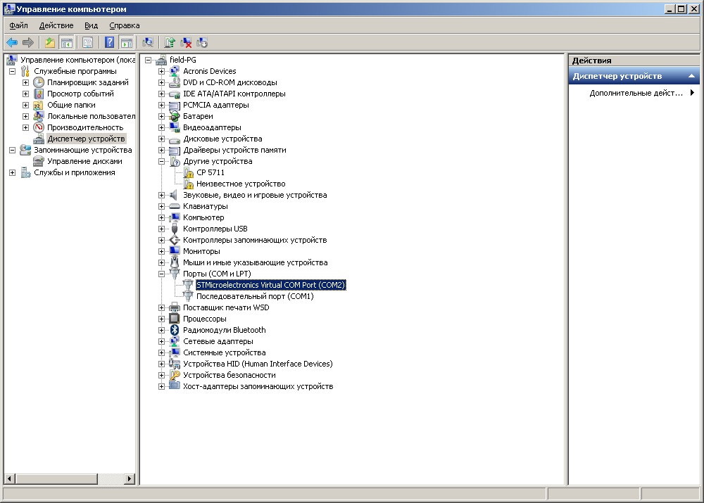
Now you can run our installed GX Developer FX. After starting the program you will have the following window:
First launch of GX Developer FX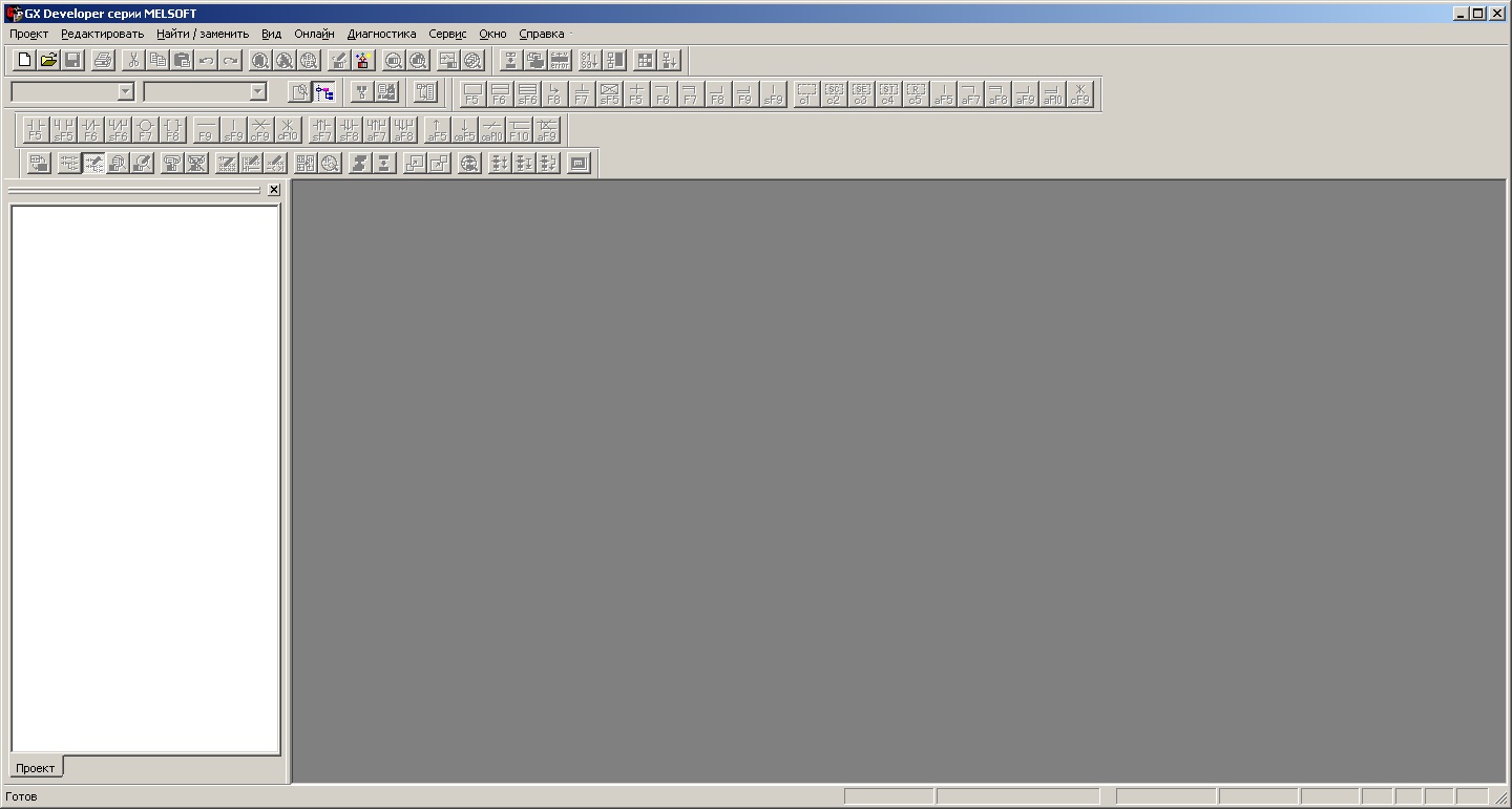
The next step is to create a new project. In the menu Project - New project. You will see this window:
New project in GX Developer FX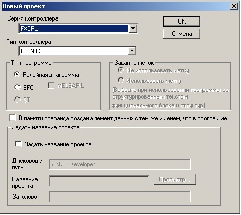
Here you can not change anything, and click OK. So, we have an empty project, and now we need to set up an online connection to the board.
To do this, select the menu Online - Transmission Settings. You will see this window:
Connection setup in GX Developer FX
Here you can not change anything, and click OK. So, we have an empty project, and now we need to set up an online connection to the board.
To do this, select the menu Online - Transmission Settings. You will see this window:
Connection setup in GX Developer FX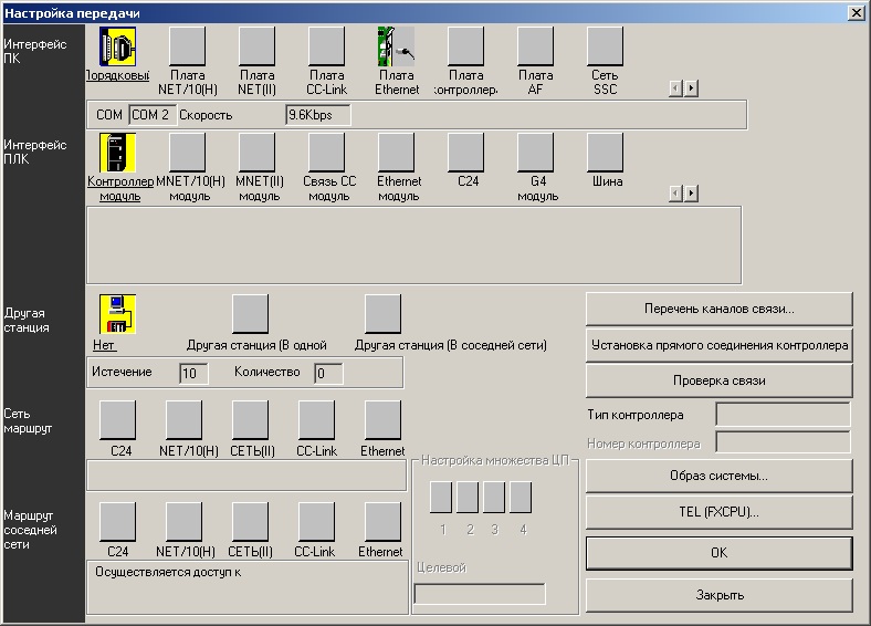
In a number of the PC Interface, select the Order (here it is incorrectly translated - there must be a
Serial) and the following window will open:
Serial port setup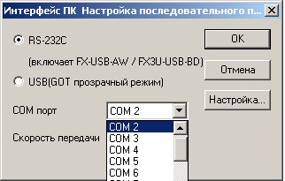
Here we select the COM port number corresponding to the one that is visible in the devices of the personal computer. It is called STMicroelectronics Virtual COM Port (COM2) in our case. Now we can check if there is a connection. To do this, click the Verify Connection button in the previous dialog. If everything is in order, then you will have a message as in the figure below:
Connection check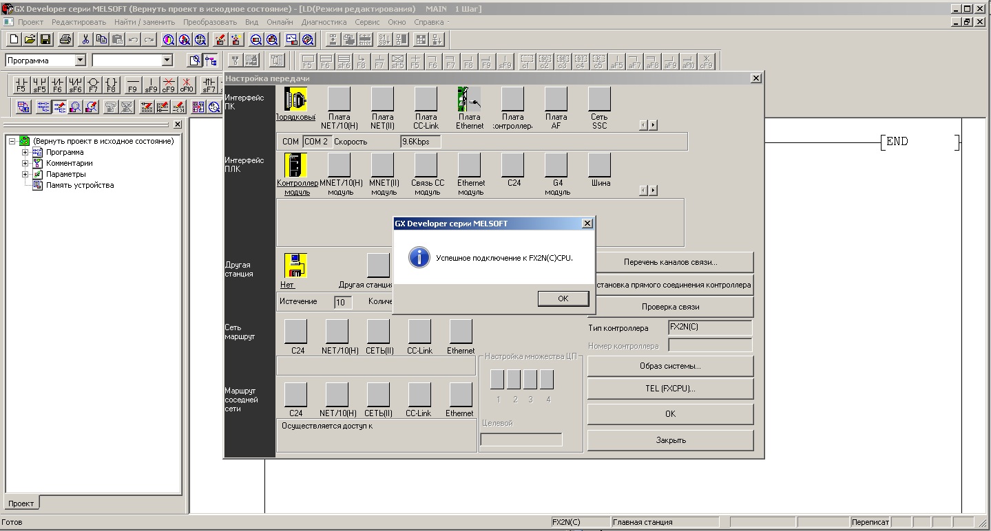
And now we can safely proceed to the most interesting - programming the controller. This version supports three languages: IL - instruction language, string display type. LAD - language of ladder logic, visual type of display. SFC is a sequential block language, a visual display type. And you can always switch between the display of IL and LAD languages and vice versa. The following is a typical LAD program:
Management Program - LAD Language
And here is the same program, but in IL language:
Management Program - IL Language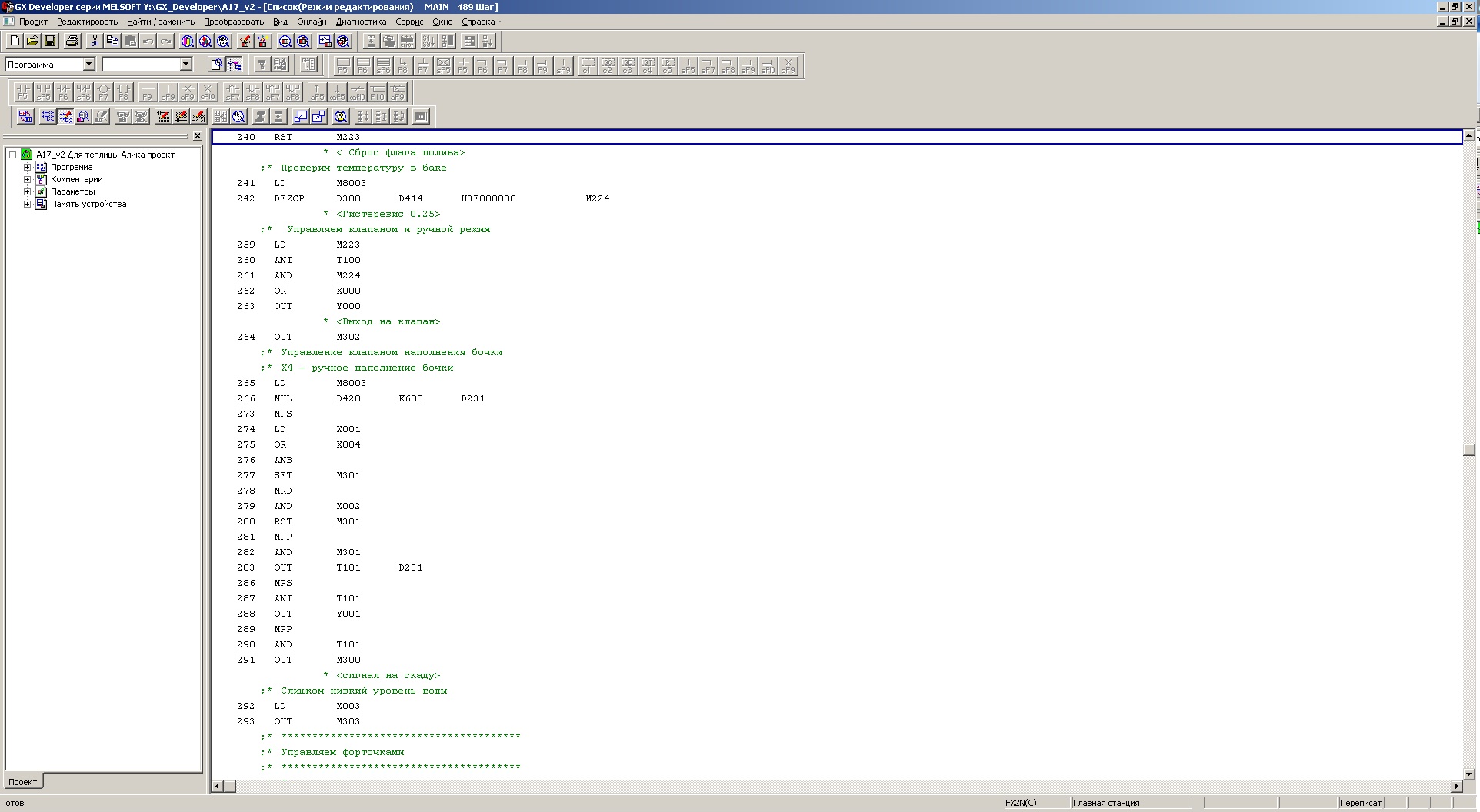
Of course, this is all well and good, but you want to look into the logic of the program - to understand what is happening there. To do this, press the F3 button - and if the program is recorded in the controller, the display will be switched to the online monitoring mode. To record a program you need to select in the menu Online - Write to controller.
This window will be shown here:
Selecting project elements to write to the controller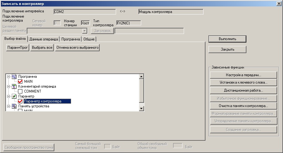
In the window, select the options for recording (the entire program and controller parameters are selected here), and click the Run button. The program will notify you that for recording the controller will be transferred to the STOP mode (you will see this by the extinction of the LED connected to the PC13 pin), it will record and put the controller into the RUN mode.
And this is how the LAD program source code will be shown online:
View of the part of the program in the LAD language in the online monitoring mode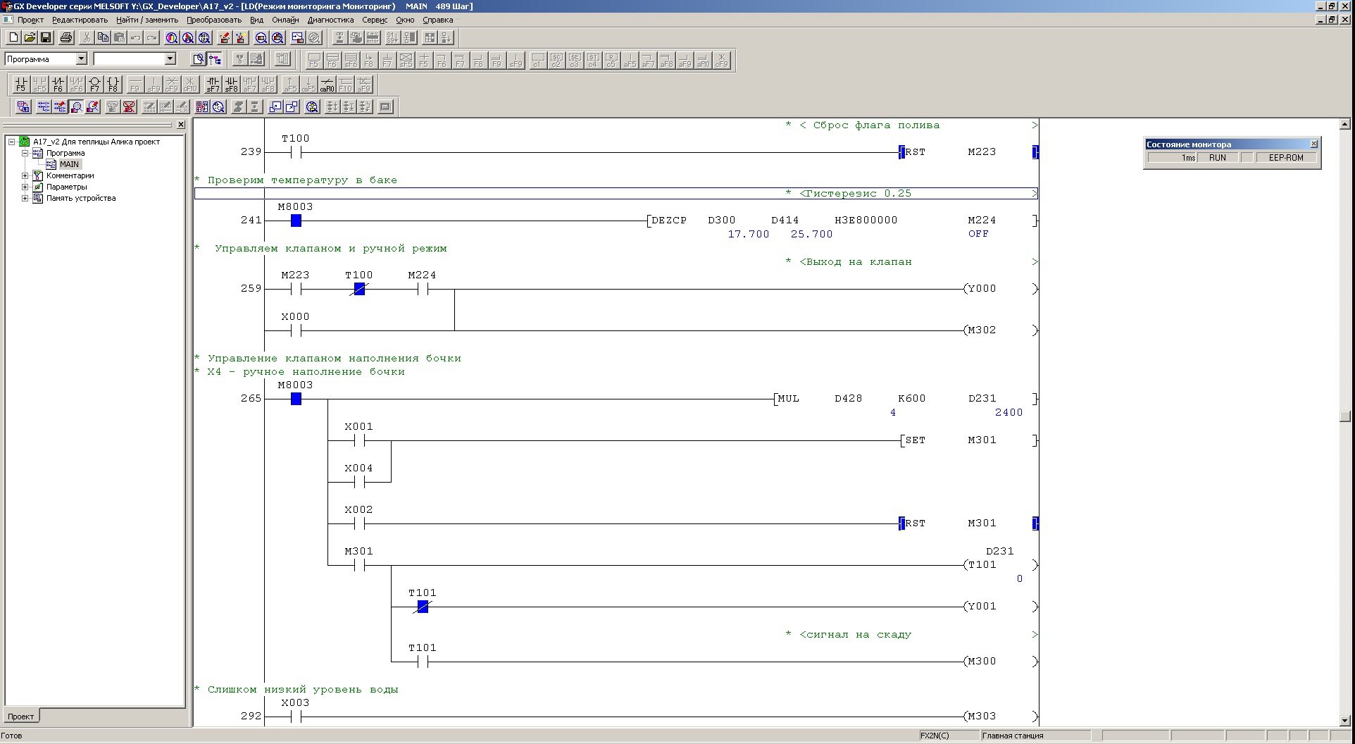
And the same part of the program in the IL language online:
View of a part of the program in the IL language in the online monitoring mode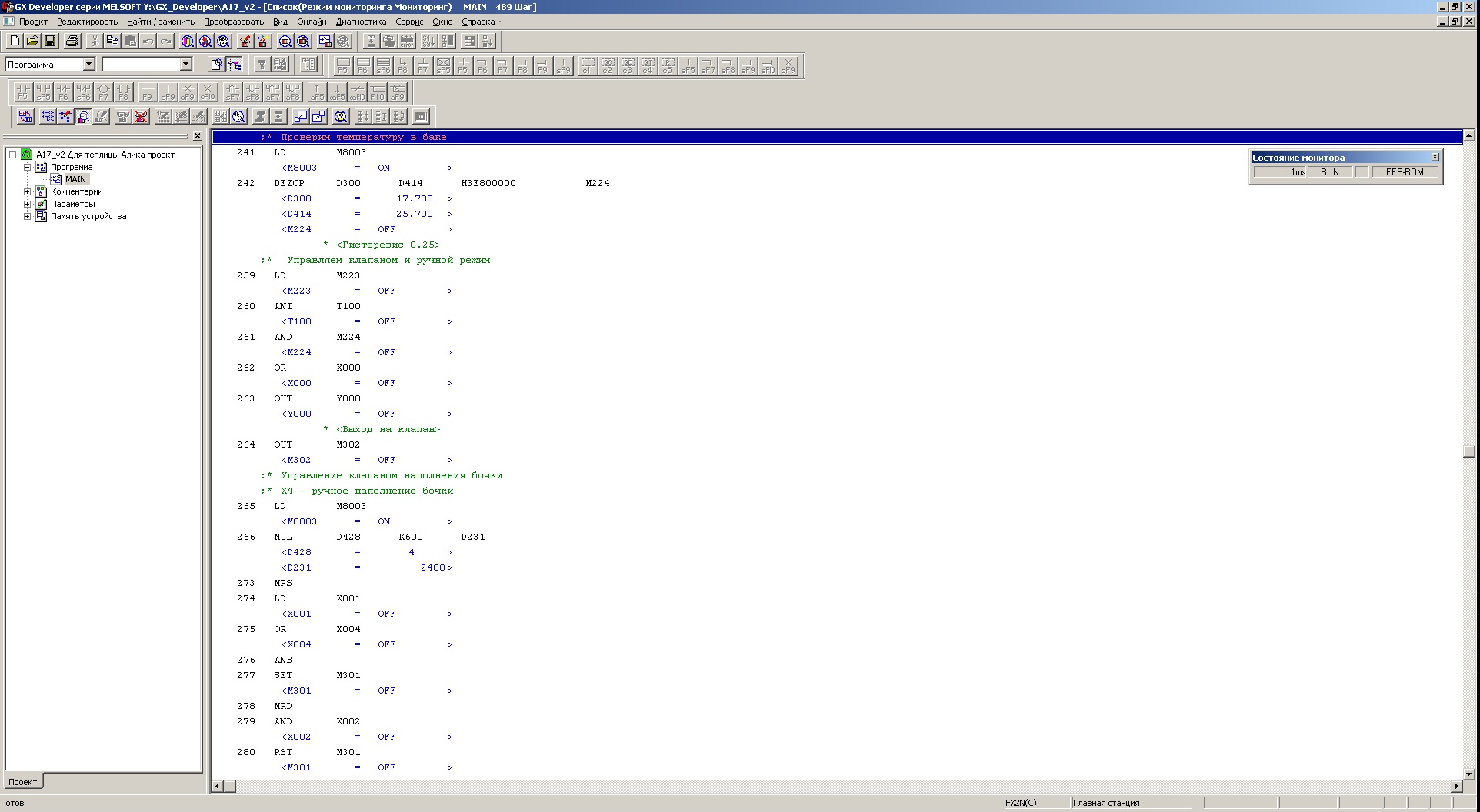
And here is the source code in the SFC language:
SFC - the appearance of the program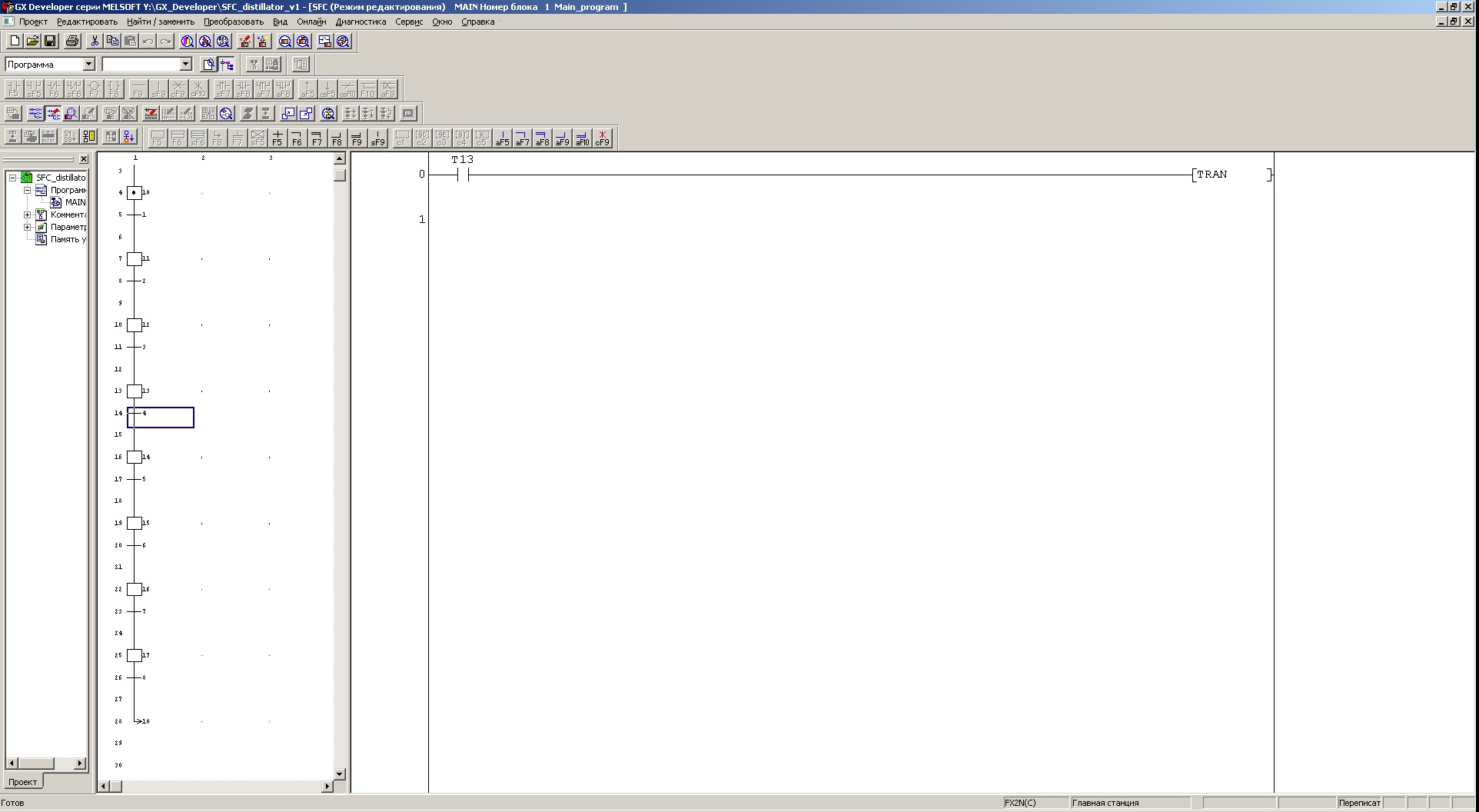
For convenience of testing, I use the old test hardware development of the controller, which for one reason or another was not used. One of these boards is shown in the figure below:
Debug Board - Intermediate Version of the Controller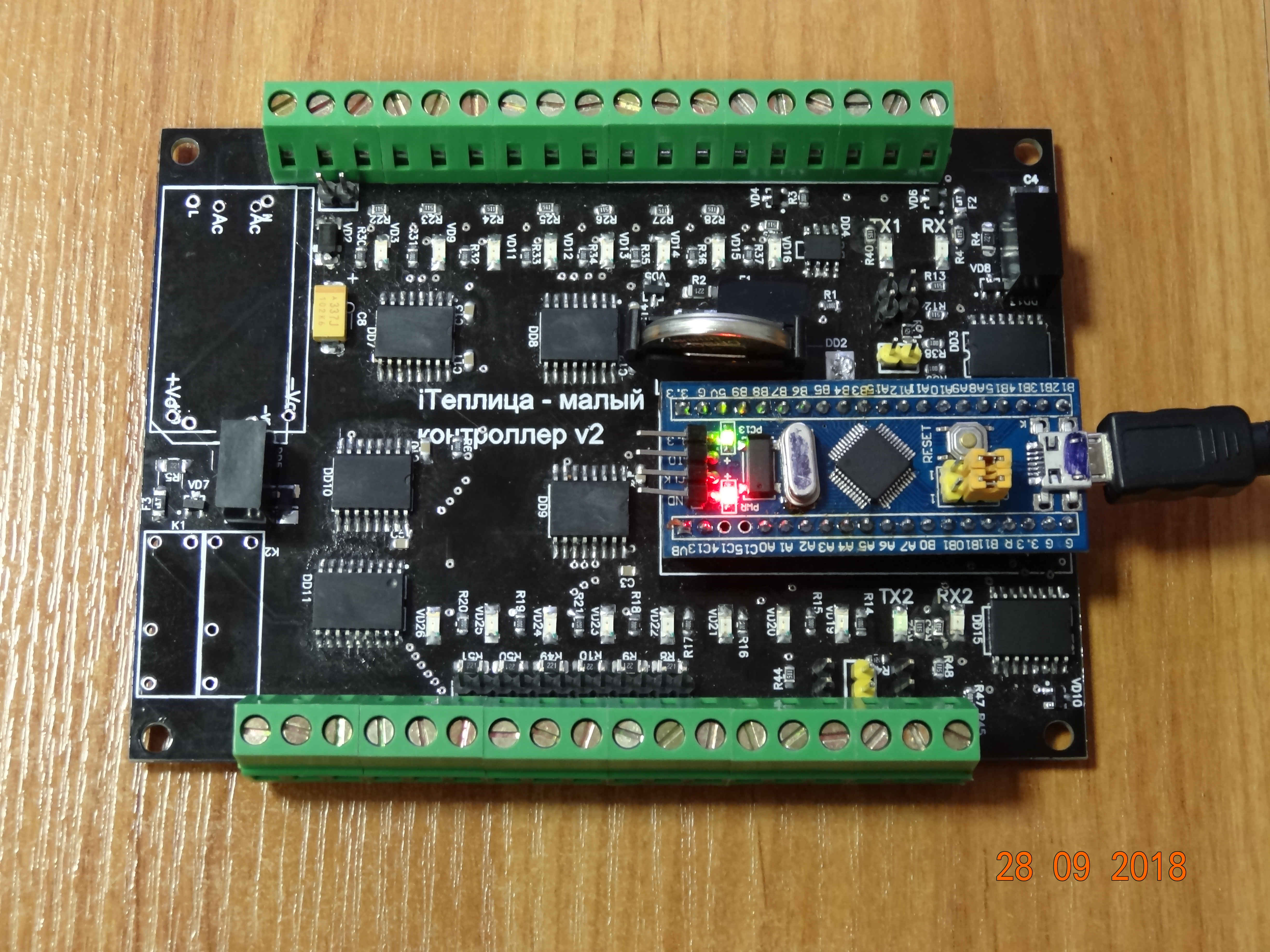
This board provides galvanic isolation for UART1, UART2 and for 1-wire bus. Also discrete inputs and outputs are galvanically isolated. The following mnemonics are accepted for the program: X1 is an input with address 1, Y2 is an output with address 2, M104 is a bit operand with address 104, D1000 is a general-purpose register with address 1000. The firmware version that is in the attachment has the following limitations: The number of program steps is 1000 (the maximum possible is 8000).
The number of registers is 2000 (range D0000-D1999). The number of bit variables is 3072 (range M0-M3071) .UART1 - support for Modbus RTU master / slave, the number of slaves in master mode is -2 (maximum possible - 128) .UART2 - support for Modbus RTU master / slave, the number of slaves in master mode is -2 (the maximum possible is 128).
The default exchange options for serial port 57600, 8N1. UART1 - in the slave mode with the address 1, UART2 - also in the slave mode with the address 2.
For the 1-wire bus, at the moment, only DS18B20 type sensors are supported, the number of slaves is -2 (the maximum possible is 128).
It also supports uploading the program from the controller and converting it into a human-readable form (I prefer LAD).
The program is built using the real-time operating system ChibiOS RT.
Configuring data exchange for modbus RTU and 1-wire buses is done using a program that you can find in the attachment. For example, now consider setting up and searching for sensors with unknown addresses. After starting the program, you will have this window:
Appearance of the configurator program after launch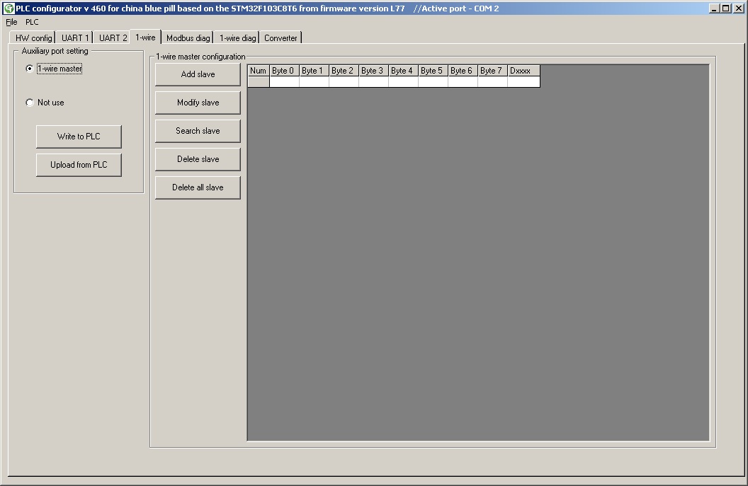
Go to the 1-wire tab and select the 1-wire master, and be sure to click the Write to PLC button to write to the controller:
Setup wizard 1-wire
And now after clicking the Search slave button, a window will open, where you can select the address in the D0000-D2000 area, starting from which the obtained temperature values will be recorded from the sensors as a floating-point number.
1-wire bus search window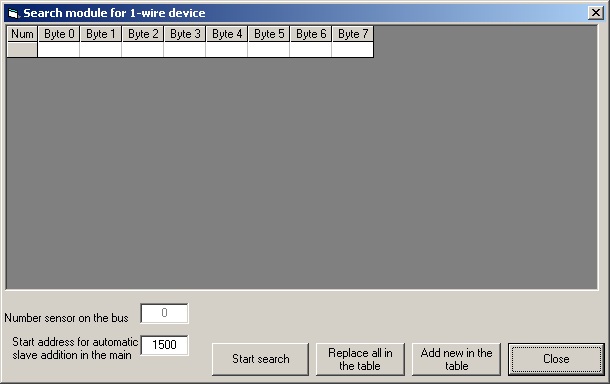
And below is a window after a successful search for all sensors connected to the data bus.
Slave search window - 3 connected temperature sensors found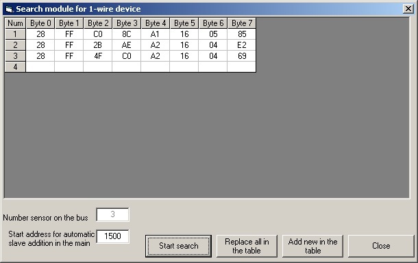
Here we can add the found sensors to the current configuration or completely replace the current one with a new one. In our case, the temperature data will be transferred to the register area of the controller by addresses D1500, D1502 and D1504 as a floating point number. It remains only to click the Write to PLC button and restart the board to activate the new hardware configuration.
Download new configuration to controller
What else can be added about the configuration program? There is one thing - the representation of floating-point numbers in the FX2N controller. To simplify the input of constants in this format, we had to use a constant record with the H modifier. As soon as the controller interpreter encounters such a modifier, it understands that it will be transferred a number in floating point format, but in the form of an IEE754 record with single precision. The program window on the Converter tab is shown below.
Conversion of floating point formats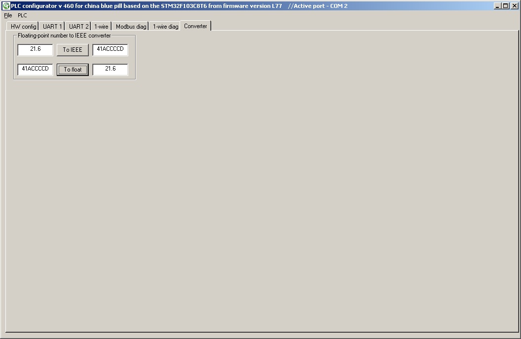
Conclusion - what did we get:
The time has come for the question - and in fact, what is the speed of such a controller? Everything is simple - when polling both data exchange ports on modbus RTU (controller in slave mode — both ports) at a speed of 500 kbps and a register request length of 122, polling 17 temperature sensors and executing the “heaviest” (consisting of binary operands) programs from 7745 steps execution cycle was equal to 21 msec. And of course there are downsides in such a controller. The first is that the blue boards are notable for the low quality of the components, and therefore I recommend to apply external power to the board before connecting mini-USB. The second is of course that there is no non-volatile memory (more precisely, it is there - but only 9 registers in the area supported by the battery). And you understand, what is the device is better not to use for demanding applications or in production. But for home or for learning - that’s what it’s cheap, affordable and understandable.
I tried to make the review extensive - and if you have any problems, write. I will be especially glad if you find errors in the implementation of the program. I hope the article will be informative and you do not waste time reading it.
Downloads for this article are below.