Making a Raspberry Keyboard Using a PS / 2 Interface
Hello, dear harazhiteli!
In this post, I'll talk about emulating a PS / 2 keyboard using a Raspberry Pi.
Recently, on one of the hot evenings, my old friend called me and asked me to write a program for him. It was necessary to automate data entry (barcodes). The outlet in which he worked belonged to a chain of Italian shops. It is clear that all work with goods was carried out in the Italian program. But due to the fact that the bulk of our country is trained to work on 1C, it was decided to conduct sales on it, and by the end of the working day upload the sales results to the Italian system. And then there were inconveniences.
For a day, the quantity of goods sold could exceed one and a half thousand positions. Entering the barcode of each of them into the Italian system has become problematic. The input algorithm was as follows: they entered a barcode, pressed "Enter" - and again. We agreed to meet in the morning and consider the options in detail.
Without thinking twice, I wrote a program that sequentially takes data from an Excel sheet and sends it to the active window. After making sure that everything works, I went to sleep.
The next day, a surprise awaited me, which for some reason I did not immediately think about. On the machine with the Italian program, there were tough group policies prohibiting the launch of third-party programs on a hash list. Admins (also Italians, by the way) did not want to take responsibility and allow the launch of third-party programs. To get around the protection system, I did not receive approval from the local leadership. It was then that the idea of solving this problem from the hardware side came (after all, no one forbids connecting a third-party keyboard). I also remembered about the Raspberry Pi, which was gathering dust at my place.
The search for documentation describing the PS / 2 interface began. Fortunately, on the first available resource (), I found all the necessary information.
As it turned out, the necessary wires for all the work were 4.
Black - earth;
Red - 5V;
Yellow - time synchronization pin (CLOCK);
White - data pin (DATA).
Colors may vary slightly. Even of these 4 wires, I needed only two - yellow and white (my device, in contrast to the keyboard, did not need in the ground and 5v).
Let's define the terminology: if there is voltage on the pin, we will consider this state as 1, otherwise 0.
By default, when the computer is able to receive data, both pins (CLOCK and DATA) are set to state 1. It is installed by the host controller on the computer’s motherboard. We accept control by supplying our voltage to both pins (the MP controller will remove its voltage). To initiate data transfer, we must send the 0th bit to the computer (not to be confused with state 0). To do this, set the state 0 to DATA and immediately after that change the state of the CLOCK pin to 0 (in this order). We made it clear to the host controller that we wanted to transmit the first bit. Now, if you return the state of the CLOCK pin to state 1, the host controller reads the first bit. Thus, we will transmit all the other bits.
The first bit is always 0, this is the start bit (let us know that we are transmitting data).
Next, we transmit 8 bits of the scan code of the key we want to press.
The tenth bit gives the parity bit (if the number of units is even, then 1, otherwise 0).
The last one, 11 bits, is a stop bit, always 1.
Thus, one data packet is formed of 11 bits.
For example, if we want to press the "0" key (scan code 45h = 1000101 in binary form), the following bit array is sent to the host controller: 01010001001.
Having accepted this data, the computer will process the command for pressing this key, but it still needs to be pressed. To do this, you must first send the F0h command, and then re-scan the key code of the key that needs to be pressed. It is also necessary to hold a pause between state changes. Empirically, I set the most suitable: 0.00020 sec if you work in Python and 1 nanosek if you code in Java.
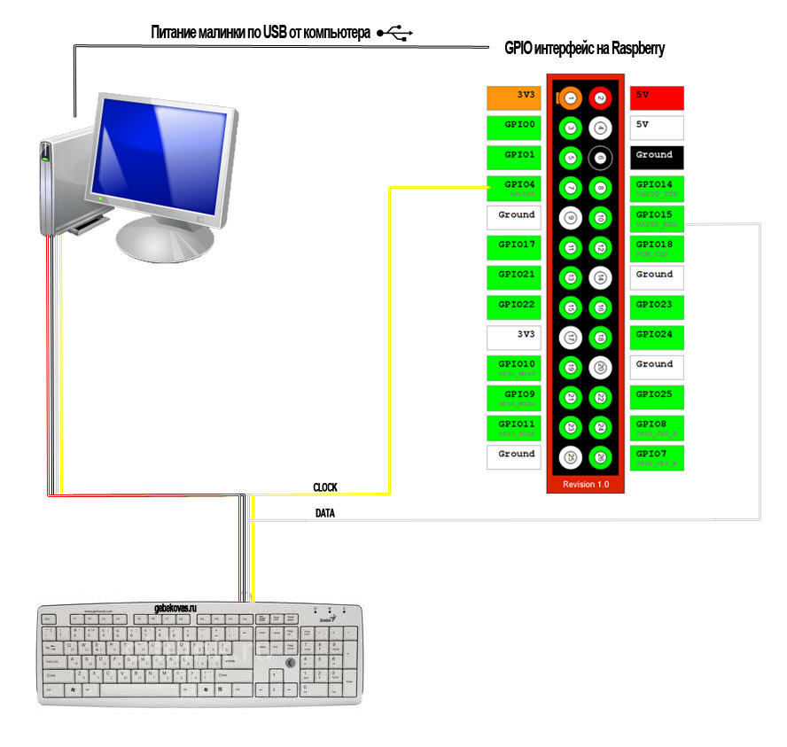
A few words about why I connected the device parallel to the keyboard. When you turn on the computer, the BIOS checks the status of the PS / 2 connectors. A computer and keyboard communicate readiness to work. The keyboard should conduct internal diagnostics and report to the computer about its readiness. Only after that does the bios allow you to work with the PS / 2 interface. I was too lazy to implement reading commands from a computer.
Now, when you turn on the computer, the keyboard will inform him of its readiness. After that, I turn on the Raspberry Pi and as soon as it takes control of the interface it will not be possible to work with the keyboard. When working, I did not identify any conflicts. Everything worked as it should, except that from time to time the computer incorrectly processed the data sent to it, and since my Raspberry was not configured to receive data (in this case, the command to resend the key code), the error was simply ignored. This problem was solved by reducing the frequency of data transmission.
First, the server side was written in Java using the pi4j library, but as the logic analyzer showed, the Java machine did not work well with delays (they turned out to be too large and the computer very often received data incorrectly). Python proved to be much better, the code ran quickly, and the system loaded several times less.
Here is the Phyton code itself:
Server side in Java:
Client side in Java:

Of course, use Raspberry for such a petty waste of pure water task. You could use Arduino or build a circuit on a cheap arm processor. But it was just an improvisation, which first came to mind, and I didn’t really want to wait until all the necessary spare parts arrived from China.
In general, I hope this experience is useful to someone. Personally, I got a lot of pleasure from the whole process.
In this post, I'll talk about emulating a PS / 2 keyboard using a Raspberry Pi.
Recently, on one of the hot evenings, my old friend called me and asked me to write a program for him. It was necessary to automate data entry (barcodes). The outlet in which he worked belonged to a chain of Italian shops. It is clear that all work with goods was carried out in the Italian program. But due to the fact that the bulk of our country is trained to work on 1C, it was decided to conduct sales on it, and by the end of the working day upload the sales results to the Italian system. And then there were inconveniences.
For a day, the quantity of goods sold could exceed one and a half thousand positions. Entering the barcode of each of them into the Italian system has become problematic. The input algorithm was as follows: they entered a barcode, pressed "Enter" - and again. We agreed to meet in the morning and consider the options in detail.
Without thinking twice, I wrote a program that sequentially takes data from an Excel sheet and sends it to the active window. After making sure that everything works, I went to sleep.
The next day, a surprise awaited me, which for some reason I did not immediately think about. On the machine with the Italian program, there were tough group policies prohibiting the launch of third-party programs on a hash list. Admins (also Italians, by the way) did not want to take responsibility and allow the launch of third-party programs. To get around the protection system, I did not receive approval from the local leadership. It was then that the idea of solving this problem from the hardware side came (after all, no one forbids connecting a third-party keyboard). I also remembered about the Raspberry Pi, which was gathering dust at my place.
The search for documentation describing the PS / 2 interface began. Fortunately, on the first available resource (), I found all the necessary information.
Keyboard PS / 2 cable pinout
As it turned out, the necessary wires for all the work were 4.
Black - earth;
Red - 5V;
Yellow - time synchronization pin (CLOCK);
White - data pin (DATA).
Colors may vary slightly. Even of these 4 wires, I needed only two - yellow and white (my device, in contrast to the keyboard, did not need in the ground and 5v).
Description of the PS / 2 protocol (keyboard -> host controller)
Let's define the terminology: if there is voltage on the pin, we will consider this state as 1, otherwise 0.
By default, when the computer is able to receive data, both pins (CLOCK and DATA) are set to state 1. It is installed by the host controller on the computer’s motherboard. We accept control by supplying our voltage to both pins (the MP controller will remove its voltage). To initiate data transfer, we must send the 0th bit to the computer (not to be confused with state 0). To do this, set the state 0 to DATA and immediately after that change the state of the CLOCK pin to 0 (in this order). We made it clear to the host controller that we wanted to transmit the first bit. Now, if you return the state of the CLOCK pin to state 1, the host controller reads the first bit. Thus, we will transmit all the other bits.
The first bit is always 0, this is the start bit (let us know that we are transmitting data).
Next, we transmit 8 bits of the scan code of the key we want to press.
The tenth bit gives the parity bit (if the number of units is even, then 1, otherwise 0).
The last one, 11 bits, is a stop bit, always 1.
Thus, one data packet is formed of 11 bits.
For example, if we want to press the "0" key (scan code 45h = 1000101 in binary form), the following bit array is sent to the host controller: 01010001001.
Having accepted this data, the computer will process the command for pressing this key, but it still needs to be pressed. To do this, you must first send the F0h command, and then re-scan the key code of the key that needs to be pressed. It is also necessary to hold a pause between state changes. Empirically, I set the most suitable: 0.00020 sec if you work in Python and 1 nanosek if you code in Java.
Connection scheme to the host controller
A few words about why I connected the device parallel to the keyboard. When you turn on the computer, the BIOS checks the status of the PS / 2 connectors. A computer and keyboard communicate readiness to work. The keyboard should conduct internal diagnostics and report to the computer about its readiness. Only after that does the bios allow you to work with the PS / 2 interface. I was too lazy to implement reading commands from a computer.
Now, when you turn on the computer, the keyboard will inform him of its readiness. After that, I turn on the Raspberry Pi and as soon as it takes control of the interface it will not be possible to work with the keyboard. When working, I did not identify any conflicts. Everything worked as it should, except that from time to time the computer incorrectly processed the data sent to it, and since my Raspberry was not configured to receive data (in this case, the command to resend the key code), the error was simply ignored. This problem was solved by reducing the frequency of data transmission.
Software part
First, the server side was written in Java using the pi4j library, but as the logic analyzer showed, the Java machine did not work well with delays (they turned out to be too large and the computer very often received data incorrectly). Python proved to be much better, the code ran quickly, and the system loaded several times less.
Here is the Phyton code itself:
import socket, select
import RPi.GPIO as GPIO
import time
#Функция посылает один бит данных к контролеру
def sendBit(pinState):
    if pinState==0:
                GPIO.output(pinData, 0)
    else:
                GPIO.output(pinData, 1)
    GPIO.output(pinClock, 0)
    time.sleep(sleepInterval)
    GPIO.output(pinClock,1)
    time.sleep(sleepInterval)
#Функция посылает массив данных на компьютер
def sendArray(args):
    GPIO.setmode(GPIO.BCM)
    #инициализация пинов,не изменяя состояние (должно оставатся 1)
            GPIO.setup(pinData,GPIO.OUT, initial=GPIO.HIGH)
    GPIO.setup(pinClock,GPIO.OUT, initial=GPIO.HIGH)
    #посылаю 0 бит
    GPIO.output(pinData, 0)
    GPIO.output(pinClock, 0)
    time.sleep(sleepInterval)
    GPIO.output(pinClock,1)
    time.sleep(sleepInterval)
    #Посылаю полученный массив данных
    for v in args:
                sendBit(v)
    #Посылаю стоп-бит
    GPIO.output(pinData, 1)
    GPIO.output(pinClock, 0)
    time.sleep(sleepInterval*2)
    GPIO.output(pinClock,1)
    time.sleep(sleepInterval*200)
    GPIO.cleanup()
pinClock=4
pinData=15
sleepInterval=0.00020
CONNECTION_LIST = []
RECV_BUFFER = 4096
PORT = 8928
server_socket = socket.socket(socket.AF_INET, socket.SOCK_STREAM)
# this has no effect, why ?
server_socket.setsockopt(socket.SOL_SOCKET, socket.SO_REUSEADDR, 1)
server_socket.bind(("0.0.0.0", PORT))
server_socket.listen(10)
CONNECTION_LIST.append(server_socket)
print "Готов принимать данные на порту " + str(PORT)
while 1:
    read_sockets,write_sockets,error_sockets = select.select(CONNECTION_LIST,[],[])
    for sock in read_sockets:
                if sock == server_socket:
                           sockfd, addr = server_socket.accept()
                           CONNECTION_LIST.append(sockfd)
                else:
                           try:
                                       data = sock.recv(RECV_BUFFER)
                                       i=0
                                       scanCode=[]
                                       print "Принял данные:"+data
                                       for bukva in data:
                                                   if bukva=="1":
                                                               scanCode.append(int(1))
                                                   else:
                                                               scanCode.append(int(0))
                                                   i=i+1
                                       sendArray(scanCode)
                                       sendArray([0,0,0,0,1,1,1,1,1])
                                       sendArray(scanCode)
                                        sock.close()
                                       CONNECTION_LIST.remove(sock)
                           except:
                                       sock.close()
                                       CONNECTION_LIST.remove(sock)
                                               continue
server_socket.close()
Server side in Java:
import com.pi4j.io.gpio.GpioController;
import com.pi4j.io.gpio.GpioFactory;
import com.pi4j.io.gpio.GpioPinDigitalOutput;
import com.pi4j.io.gpio.PinState;
import com.pi4j.io.gpio.RaspiPin;
import com.pi4j.io.gpio.event.GpioPinDigitalStateChangeEvent;
import com.pi4j.io.gpio.event.GpioPinListenerDigital;
import com.pi4j.io.gpio.GpioPinDigitalInput;
import com.pi4j.io.gpio.PinPullResistance;
import java.net.ServerSocket;
import java.net.Socket;
import java.io.IOException;
import java.io.BufferedReader;
import java.io.InputStreamReader;
import java.io.PrintWriter;
class controller {
	private static int[] sc1 = {0,0,0,0,1,1,1,1,1};  //F0h
	private static int port = 8928;
	public static GpioController gpio=GpioFactory.getInstance();
	public static GpioPinDigitalOutput pinClock = gpio.provisionDigitalOutputPin(RaspiPin.GPIO_07,"Com1", PinState.HIGH);
	public static GpioPinDigitalOutput pinData = gpio.provisionDigitalOutputPin(RaspiPin.GPIO_16,"Com2", PinState.HIGH);
	public static void main(String[] args) throws IOException {
		//Инициализация сокет сервера и клиента
		ServerSocket server=null;
		try {
			server = new ServerSocket(port);
		}  catch (IOException e) {
			System.err.println("Could not listen on port:"+port);
			System.exit(1);
		}
		Socket client = null;
		System.out.println("Готов принимать данные!");
		while (true)
			{
				try {
					client = server.accept();
					BufferedReader in = new BufferedReader (new InputStreamReader (client.getInputStream()));
					String line;
					while ((line = in.readLine())!=null)
						{
							if (line.indexOf("exit")>-1) {
								return;
							}
							else
							{
								//Записываю в массив полученные данные
								int[] buf=new int[9];
								for (int i=0; i<9;i++)
								{
									buf[i]=Integer.parseInt(line.substring(i,i+1));
								}
								System.out.println("Получил пакет:  "+line);//Посылаю под клавиши
								signal(buf);
								//Посылаю код отжатия клавиши F0h
								signal(sc1);
								//Посылаю код клавиши
								signal(buf);
								PrintWriter  out   = new PrintWriter (client.getOutputStream(), true);
								out.print("finished\r\n");
								out.flush();
							}
						}
					}
			}
			catch (IOException e)
			{
				client.close();
				System.out.println("Shutdown gpio controller");
			}
		}
	}
	//Функция устанавливает состояние на указанном пине
	static private void setPin(GpioPinDigitalOutput pinObj,int signalByte) {
		if (signalByte==0) {
			pinObj.low();
		} else {
			pinObj.high();
		}
	}
	//Функция посылаем биты с массива
	static private void signal(int[] bits) {
		int sleepInterval=1;
		//Посылаю стоп-бит
		setPin(pinData,0);
		setPin(pinClock,0);
		sleeper(sleepInterval);
		setPin(pinClock,1);
		sleeper(sleepInterval);
		// Посылаю массив данных
		for (int i=0; i<9; i++) {
			setPin(pinData,bits[i]);
			setPin(pinClock,0);
			sleeper(sleepInterval);
			setPin(pinClock,1);
			sleeper(sleepInterval);
		}
		//Посылаю стоп-бит
		setPin(pinData,1);
		setPin(pinClock,0);
		sleeper(sleepInterval*2);
		setPin(pinClock,1);
		sleeperM(1);
	}
	//Функция устанавливает задержку в макросекундах
	static private void sleeper(int i) {
		try {
			Thread.sleep(0,i);
		} catch(InterruptedException e) {
			System.out.println("Sleepin errore");
		}
	}
	//Функция устанавливает задержку в милли секундах.
	static private void sleeperM(int i) {
	try {
			Thread.sleep(i);
		} catch(InterruptedException e) {
			System.out.println("Sleepin errore");
		}
	}
}
Client side in Java:
import java.net.ServerSocket;
import java.net.Socket;
import java.io.IOException;
import java.io.BufferedReader;
import java.io.InputStreamReader;
import java.io.PrintWriter;
import java.util.Scanner;
class tcpClient {
	private static int port = 8928;
	public static void main (String[] args) throws IOException {
		String host="localhost";
		Socket server;
		PrintWriter out=null;
		Scanner sc= new Scanner (System.in);
		System.out.println("Input host adress:");
		host=sc.nextLine();
		System.out.println("Connecting to host "+host+"...");
		try {
			server = new Socket(host,port);
			out = new PrintWriter (server.getOutputStream(), true);
		} catch (IOException e) {
			System.err.println(e);
			System.exit(1);
		}
		System.out.println("Connected!");
		BufferedReader stdIn = new BufferedReader (new InputStreamReader(System.in));
		String msg;
		while ((msg = stdIn.readLine()) != null) {
			out.println(msg);
		}
	}
}
An example of a digitized signal sent from my device to a computer. Bottom channel CLOCK, top DATA. I send signals from Python
Conclusion
Of course, use Raspberry for such a petty waste of pure water task. You could use Arduino or build a circuit on a cheap arm processor. But it was just an improvisation, which first came to mind, and I didn’t really want to wait until all the necessary spare parts arrived from China.
In general, I hope this experience is useful to someone. Personally, I got a lot of pleasure from the whole process.